

Audio Telex AT120-3, AT60-3 User Manual
g
o
-
AMrilDilril@
COMMUNICATIONS
ft{lTl
o
5
l-
a
g
c
-
Mixer
^6,
Audio Telex
NSW & ACT
149 Beaconsfleld
Prlvate
Sllverwater NSW 2'128
Austrella
Ph02s64T 14't1
Fax 02 9648 3698
Bag
Street
149
AT60-3
&
ATI
Communications Pty Ltd
001345482
ACN
42 Commercaal Road
Fortltude Valley
20-3
Amplifiers
lncorporatsd ln t{SW
QLD
Ph 07 3852 1312
Fax 07 32521237
& NT
PO Box 871
QLD
2!277 nudlEDp,rough Road
4006
Blackbum South VIC
3
A{.
ffi
ColtF
r*l'!ll
iErta
Box Hlll VIC
PO Box
Ph 03 9890 7477
Fax 03 9890 7977
3128
'15'l
3130
$
l-
o
7/64€6
Cannlngton
Ph 08 9356 2761
Fax 08 9356 2762
Kent Street
PO Box
489
WA 6107
El€ctronlc
Thebarton SA
PO Box 7034
Unlt
Concepts Pty
76
George Street
Adelald€ SA 5000
Ph 08 8234 9444
Fax
08 8234 9441
B,
11 Plermark Orlve
PO Box 5{ 2
Albany NZ 1331
Ph 09 415 9426
Fax 09 415 9864
5031
Hutt Stre€t
Ltd
K W tcculloch
&la Alb€rt Road
lroonah TAS 7009
Ph 03 6228 6373
Fax 03 6278 1063
Pty Ltd
AT60-3
Mixer
Amplifier
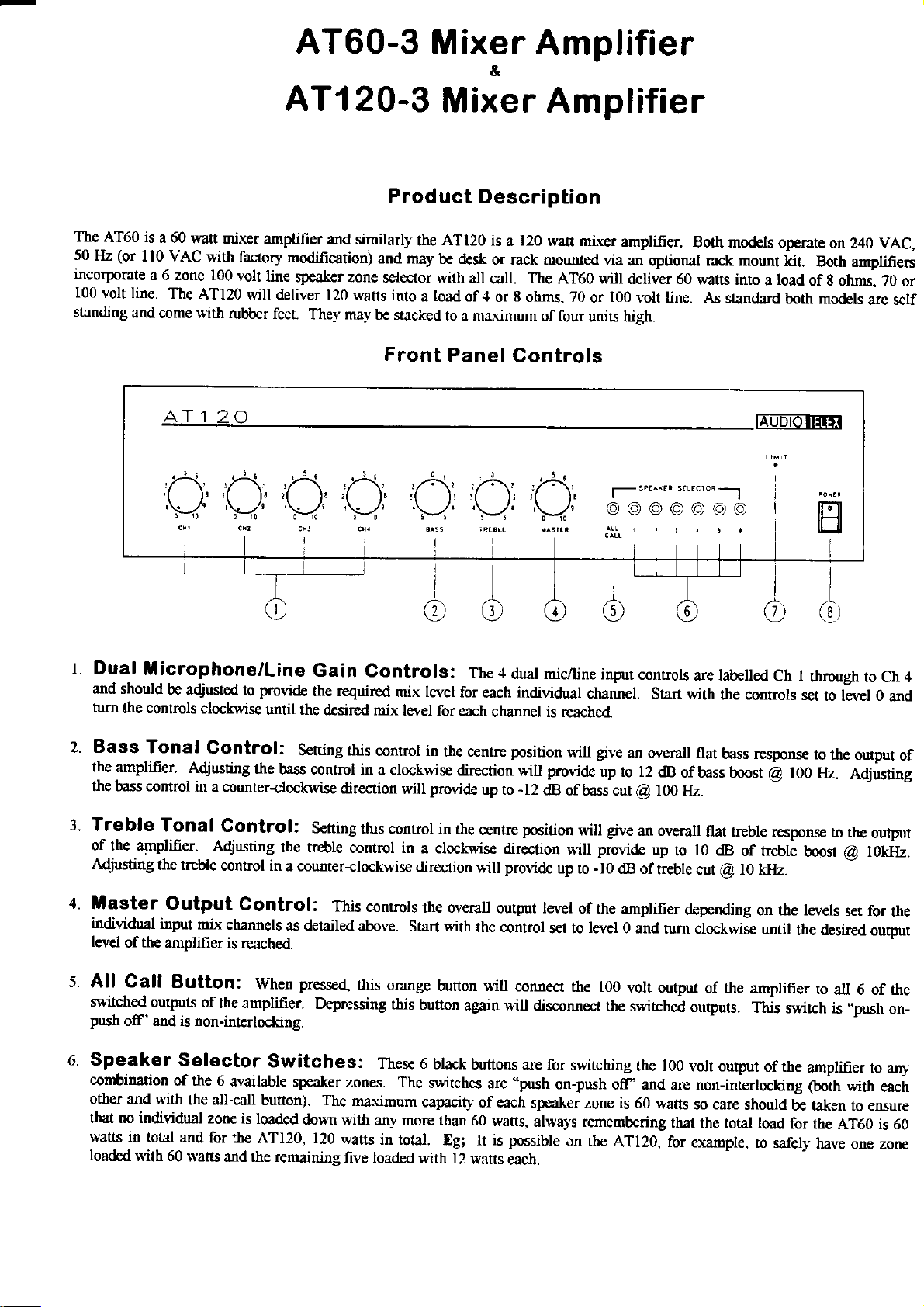
Th9
AT60 is
(or
50
Hz
incorporate
100
volt line.
standing
and
a 60
$€tt mixer
I l0 VAC
a 6 zone 100
come with
The
with factory
AT120
Ar 1
amplifier
volt
line
will
rubber feet.
20
ATI 2O-3
Product
and
similarly
modificauon)
sfraker zone
deliver 120 watts into
They may
and may
selector with
be stacked
Front
Mixer
Description
ATl20
the
a
be desk
load
is
l2o
a
or rack mounted
all
of
to a maximum
call.
.l
or
The
8
ohms. 70
Panel Controls
Amplifier
*ztt mixer
A,T60 will
of four
amplifier.
via
an optional rack mount
deliver 60
100
or
volt line. As
units high.
Both models
operate
kit.
watts into a load
standard
both models
EuDionirft
on 240 VAC,
Both amplifie6
g
of
otrms, ZO
are self
or
t. Dual
and should
turn
Bass
the amplifier'
the bass control
3.
Treble
llicrophone/Line
the controls
Tonal
of the amplifier.
Adjusting
4.
aster
individual
level
of the amplifier
5.
All Call
switched outFrts
push
of' and is non-interlocking.
Speaker
combination
other
and with
that no individual
watts in
loaded
total
with 60
be adjusted
clockwise
Control:
Adjusting
in
a counter-clockwise
Tonal
Adjusting
the treble
Output
iryut
mir
Button:
of
Selector
of fte 6
the all-call
zone is
and for the
watts
Gain
provide
to
until the
the
Control:
the rcquired
Sening this
bass control in
Setting
&e Feble
control in
a counter-clockwise
Control:
channels
is reached
the amplifier.
When
as detailed
pressed,
Depressing
Switches:
available speaker
button).
loaded
and the remaining
down
ATl20, 120
Controls:
mix levet
desircd mix
direction
control in
This
zones.
The maximum
with
watts
five loaded
level for
contml in
a clockwise
will
this control
controls
above.
this orange
this
Thes€ 6
The
any morc than 60
in total.
for
each
the cente
direction
provide
in the
a clockwise
direction
the overall
Start with
button wilt
button
again will
black
switches
capacity
Eg; It is
with l2
The +
duat mic/line
individual
each
channel is reached"
position
provide
will
-12
up to
centre
will
output level
the control
buttons are for
dB
position
direction
provide
s€t to
connect
disconnect
are'push
of each slBaker
watts,
always remembering
pnssible
wans
each.
inpur
channel.
give
will
up ro 12
of bass o,tr
give
will
provide
will
-lO
up
to
dB of
of the arnplifier
level
0 and
the 100
the switcha
swirching
on-push
on
off'and are non-interlocking (boi6
zone is 60
the ATl20, for
controls
Start with
an
overall flat
dB
of bass boo tt
loo Hz.
@
an overall
up
to
treble cut
depending
tum
volt output
ofiputs. fnis
rhe 100
volr output
watts
that
are labelled
the controls
bass response
ch I
q
flat treble
lo
dB
@
clockwise until
of rhe
so care
the total load
example,
response
of rebt;
lO l'l]|z.
on the levels
amplifier
of the
should
to safely
through
set to level 0
!o
the output
rco ut.
to the
boosr
the d€sired
to
all 6 of the
swiah is
amplifier
be taken
for the
AT60 is 60
have
ro Ch 4
Adjusting
output
g
touiy.
set for
output
,.push
to any
with
eacir
to ensure
one zone
and
of
the
on-
 Loading...