

DETECTIV User Manual
Part No: 2-400-0001

2 AUDIOTEL INTERNATIONAL MN400872 Issue 1 (08/04)
DETECTIV User Manual
AUDIOTEL INTERNATIONAL MN400872 Issue 1 (08/04) 3
© 2004 Audiotel International Ltd
Under the copyright laws, this manual may not be copied, in whole or part, without the written
consent of Audiotel International Ltd.
Every effort has been made to ensure the accuracy of this manual. The instructions and descriptions are accurate at the time of publication. However, succeeding versions of the equipment and
manuals are subject to change without notice. Audiotel assumes no liability for damages incurred
directly or indirectly from errors, omissions or discrepancies between the equipment described
and the manual.
If you have any comments or suggestions on improving this manual please contact Audiotel at the
following address:
Audiotel International
Corby Road
Weldon
CORBY
Northants
NN17 3AR
Fax: +44 (0)1536 266711
or Email us at: marketing@audiotel-international.com
DETECTIV™
is a registered trademark of Audiotel International Ltd
AUDIOTEL™ is a registered trademark of Audiotel International Ltd

AUDIOTEL INTERNATIONAL MN400872 Issue 1 (08/04) 3
How to use this manual..................................................................................4
CE MARK EMC COMPLIANCE AND RADIO TYPE APPROVAL...... 5
INTRODUCTION.................................................................6
GETTING STARTED - ........................................................ 8
Charging the battery.......................................................................................9
Switching the unit ON (and Off) ................................................................... 10
Using the controls and selecting options .....................................................11
Setting time & date ......................................................................................12
BASIC OPERATING METHODOLOGY..................................... 13
DETECT ........................................................................................................ 13
IDENTIFY......................................................................................................13
LOCATE........................................................................................................ 13
DETECT MODE ............................................................14
Selecting a Detector .....................................................................................15
Setting the unit Volume................................................................................ 16
Transmitter Detector Alarms ........................................................................16
NLJD Display................................................................................................17
Enabling / Disabling the NLJD ...................................................................... 17
IDENTIFY MODE.......................................................... 18
Broadband CW Identify screen.....................................................................18
Broadband Burst IDENTIFY screen ..............................................................19
Harmonic Receiver IDENTIFY screen........................................................... 20
NLJD & Metal Detector IDENTIFY screen ...................................................22
LOCATE MODE ............................................................ 25
EVENT LOG................................................................... 26
Alarms ..........................................................................................................27
Snapshots..................................................................................................... 27
References ................................................................................................... 28
CONNECTION, DOWNLOAD TO A PC .................................. 29
ACCESSORY .................................................................. 30
APPENDIX A - BATTERY & I/O ........................................32
APPENDIX B - MENU STRUCTURE..................................... 33
Contents

4 AUDIOTEL INTERNATIONAL MN400872 Issue 1 (08/04)
DETECTIV User Manual
AUDIOTEL INTERNATIONAL MN400872 Issue 1 (08/04) 5
How to use this manual
This manual is divided into a number of sections. The
following brief description shows the type of information
presented in each section:
Introduction to DETECTIV – a brief description of DETECTIV and how it works.
Getting Started - Setting up and looking after your DETECTIV – contains a packing list of
the DETECTIV system. Details of the power requirements and battery care. How to set up
DETECTIV ready for operation.
Basic Operation – describes the basic procedures for using DETECTIV. This is not meant to
be an exhaustive description of DETECTIV's capabilities or functionality, merely a quick guide
to allow basic searches to be carried out. The following Mode sections give more details of the
various modes and their use, in relation to the different detectors.
Detect Mode – describes operating in this mode, which uses all of DETECTIV's detectors
simultaneously, and interpreting the multi-detector display.
Identify Mode – describes how to navigate through the different detector's Identify screens and
how to use them to identify whether or not a detected response is a possible threat.
Locate Mode – this section describes how to use DETECTIV to locate accurately the source of
any identied threat.
Event log – Gives details of the three Logs available within DETECTIV - Alarms, Snapshots and
Reference. How entries are generated and what they are used for.
Connection, download to a PC - gives details of how to connect to a PC and download Event log
information.
Appendices - Reference information about the DETECTIV unit, its component parts, controls
and menu structure.

AUDIOTEL INTERNATIONAL MN400872 Issue 1 (08/04) 5
Warnings
When operating the equipment within Europe where Type Approval is a legal requirement, all
equipment, including transmitter, receivers, microphones, batteries and aerials must be to type
approved standard in order for the system to remain type approved. Therefore, only equipment
supplied by Audiotel International should be used.
It is the operator's responsibility to operate the equipment only on frequencies licensed to them.
FCC
NOTE This equipment has been tested and found to comply with the limits for a Class
B digital device, pursuant to part 15 of the FCC Rules. These limits are designed
to provide reasonable protection against harmful interference in a residential
installation. This equipment generates, uses and can radiate radio frequency
energy and, if not in-stalled and used in accordance with the instructions,
may cause harmful interference to radio communications. However, there is
no guarantee that interference will not occur in a particular installation. If this
equipment does cause harmful interference to radio or television reception, which
can be determined by turning the equipment off and on, the user is encouraged to
try to correct the interference by one or more of the following measures:
—Reorient or relocate the receiving antenna.
—Increase the separation between the equipment and receiver.
—Connect the equipment into an outlet on a circuit different from that to which
the receiver is connected.
—Consult the dealer or an experienced radio/TV technician for help.
CE MARK EMC COMPLIANCE AND
RADIO TYPE APPROVAL
The CE mark is afxed to the DETECTIV to conrm
compliance with the following European Community
Directives:
Council Directive 89/336/EEC on the approximation of
Laws of Member States relating to Electromagnetic
Compatibility and the following EMC and Radio Type
Approval standards:
EN 300 220-1
EN 300 440-1
EN 301 489-3
EN 300 330-1
EN 60950 LVD

6 AUDIOTEL INTERNATIONAL MN400872 Issue 1 (08/04)
DETECTIV User Manual
AUDIOTEL INTERNATIONAL MN400872 Issue 1 (08/04) 7
INTRODUCTION
DETECTIV is a sophisticated search tool integrating four
detection sensors to provide a more complete and robust
method of detecting electronic eavesdropping devices.
Four tried and tested detection methods: Harmonic receiver, broadband detector, Non-linear
junction detector and metal detector are integrated into one compact, easy to use unit.
Combining four complementary sensor systems together means more effective and efcient
search capability. With just one physical sweep of a target area four separate searches are carried
out. DETECTIV automatically switches between the four sensors using each detection method
in turn, ve times a second, allowing a continuous display of all detector activity.
Each sensor provides information which combines to provide a comprehensive picture of
any concealed targets. DETECTIV presents the multisensor information in a simple, easily
understood bar graph display. Additional expert screens give access to more detailed information
for each of the sensors. Using multiple detector information in this way improves detection and
gives more accurate identication between false alarms and real targets.
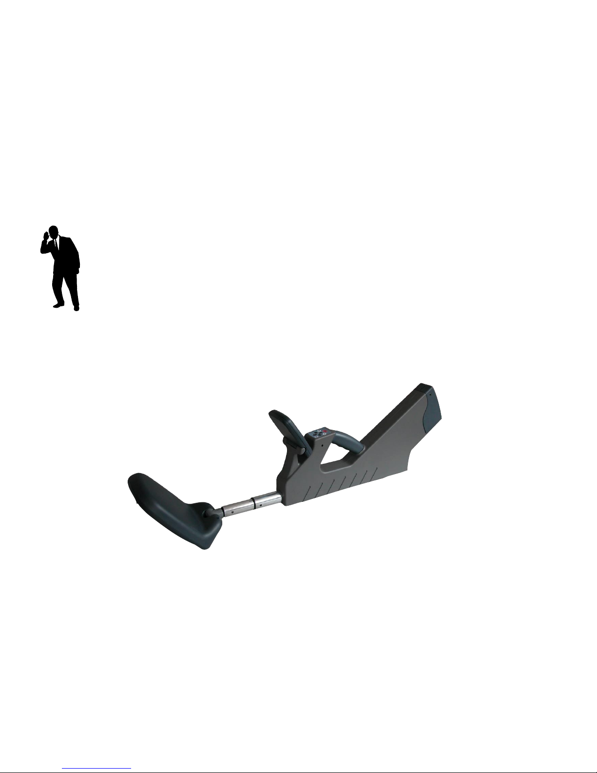
The Unit
The DETECTIV unit, shown opposite, is a hand-held case with a paddle shaped search head on
an extendable arm. Controls are grouped next to the handle for convenient thumb operation and
information is presented on a tilt-able TFT LCD touch-sensitive screen.
The input and output ports are grouped together under the tail of the unit along with the battery
compartment. The On /Off switch, audio output and headphone socket are conveniently located
at the top of the unit tail.
Handling
The extendable search head contains all the DETECTIV sensors and during a sweep search
needs to be passed close to all parts of a target area. Rotatable on two axis the head can be
twisted to provide the best attitude and position for searching most surfaces. The extendable arm
provides convenient access for the difcult to reach parts of a typical target area, for example,
ceilings and under desks. To minimise strain the unit has provision for a shoulder strap allowing
DETECTIV to be handled like a guitar and is designed to be balanced with the search head arm
extended approximately half way. The tail of the unit is also designed to provide a convenient
handle to control the unit when searching high surfaces.

AUDIOTEL INTERNATIONAL MN400872 Issue 1 (08/04) 7
Shoulder strap xing points
(mounted on both left and right sides)
Headphone socket
Battery Comparment
Input/output sockets
Search Head
Extendable Arm
Tiltable LCD touch- sensitive Display
Control keypad
Hand grip
Battery charge indicators
On/Off switch
Loudspeaker

8 AUDIOTEL INTERNATIONAL MN400872 Issue 1 (08/04)
DETECTIV User Manual
AUDIOTEL INTERNATIONAL MN400872 Issue 1 (08/04) 9
Out of the box
DETECTIV can be ordered with a number of accessories. The actual specication of the
accessories will vary from country to country dependent on supply voltage.
The Basic DETECTIV (order no: 2-400-0001) consists of:
DETECTIV unit
Li-Ion battery pack (7.2V)
Multi-media Memory card
DETECTIV manual
The accessories which can be ordered separately are:
Item Order code
Li-ion battery pack 2-400-0002
AC/DC Power adaptor 2-400-0003
Mains power lead (dependent on country)
Shoulder strap 2-400-0005
Pelicase with foam inserts 2-400-0006
Headphones (folding) 2-400-0007
Stand-alone Li-ion battery charger 2-400-0008
Multi-media memory card 2-400-0009
Lightweight carry case 2-400-0012
Test target kit 2-400-0013
GETTING STARTED -
This section covers setting up DETECTIV ready for
operation with a basic description of the controls and how
to use DETECTIV to locate eavesdropping devices.
AUDIOTEL INTERNATIONAL MN400872 Issue 1 (08/04) 9
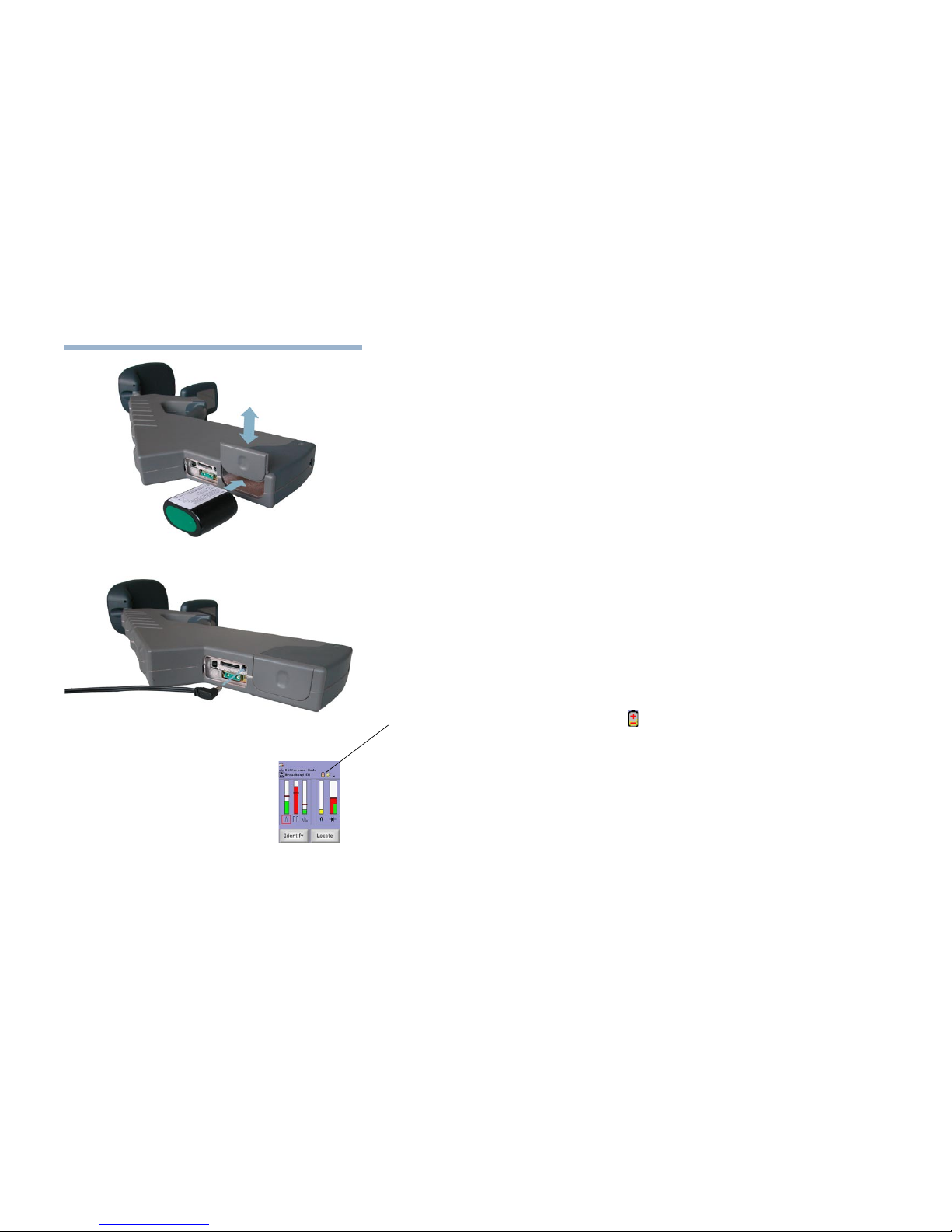
Charging the battery
The DETECTIV battery packs are supplied without being charged. To operate the DETECTIV
you must rst charge the internal battery.
Remove the battery door from the unit and insert the battery, (the end with the four
contacts goes in rst), into the battery compartment.
Replace the battery compartment door and place the unit on charge by connecting an
appropriate AC/DC adaptor to the Charger socket. When successfully connected to a
live power supply the red LED next to the On/Off switch lights to indicate the battery
is being charged.
Note It is not necessary to switch DETECTIV On to charge the battery.
When the battery is fully charged, the red LED turns off and the green LED lights. The unit is now
ready for use.
Battery
The Internal rechargeable Lithium Ion battery pack gives approximately 2 hours continuous use;
Automatically recharged when external power is applied to the DETECTIV via an external AC/
DC Adaptor. Internal protection circuitry protects the battery. If for any reason the battery suffers
any transient fault such as short-circuit, overcharging or deep discharge, the pack will shutdown. It
will remain in this state until reactivated by connection of an external AC/DC Adaptor.
When the battery charge is low a battery icon is displayed on the display screen . This will
indicate there is approximately enough power to keep DETECTIV operating for a further 10
minutes. If the battery is completely exhausted the display will icker and fail.
Inserting the battery
Connecting an AC/DC adaptor
10 AUDIOTEL INTERNATIONAL MN400872 Issue 1 (08/04)
DETECTIV User Manual
AUDIOTEL INTERNATIONAL MN400872 Issue 1 (08/04) 11
Multi-media Memory card
A Multi-media memory card is used to allow screen shots and log information to be stored and
transferred to a PC for further analysis and reporting. DETECTIV can be operated without a
multimedia memory card installed although you will be unable to save screen shots or any log
records.
Note DETECTIV should be off when a ash memory card is inserted into the
memory card slot. The contacts on the memory card should be facing away from
the accessory socket when inserting the Mulitmedia card.
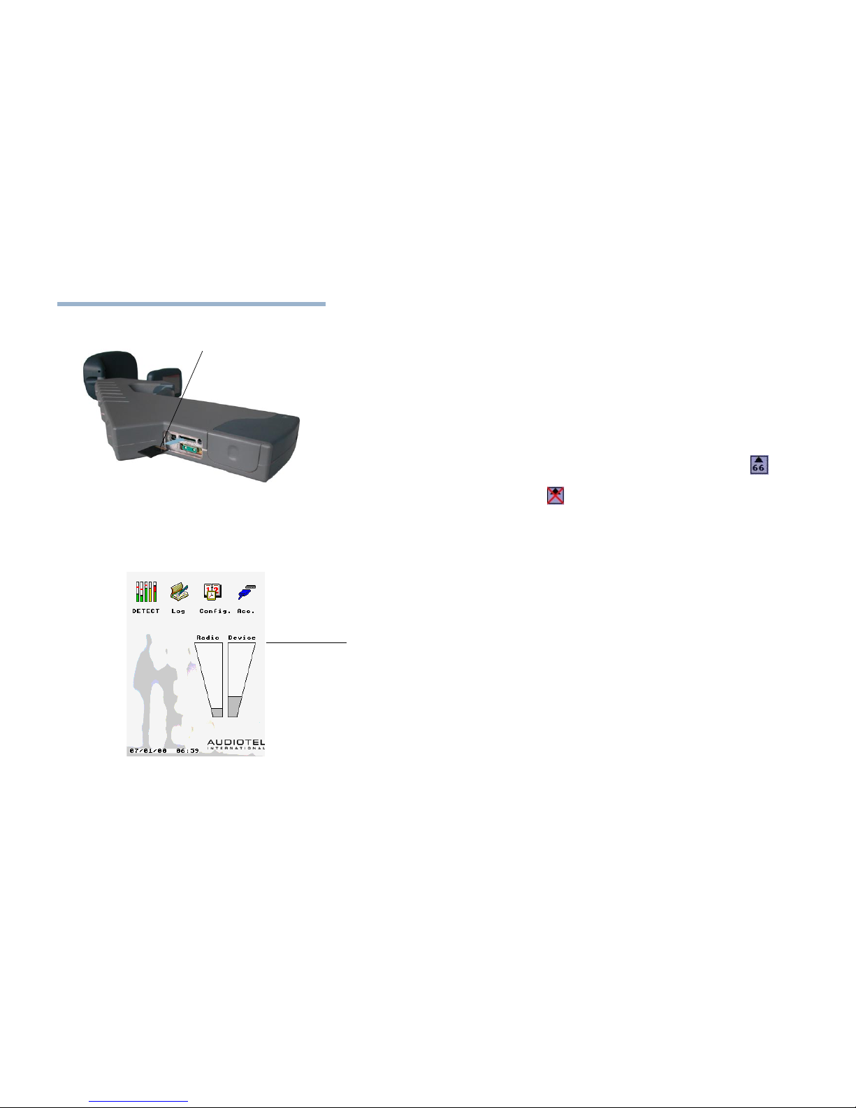
The number of screen Snapshots that can be stored is displayed in a Snapshot counter sc in the
upper section of the display on all DETECT and IDENTIFY screens. If no memory card is installed
the Snapshot counter is crossed out in red sc .
Switching the unit ON (and Off)
To switch the unit ON press and hold the ON / OFF switch for a second or two.
The Unit performs an initialising sequence displaying the message 'Please Wait'.
Note During the initialising sequence the various detectors are calibrated. To ensure the
best performance from DETECTIV the search head should be kept clear of any
potential targets during this calibration.
Once the initialising sequence is completed the Main Menu is displayed.
To switch the unit OFF press and release the On/Off switch.
The back light will turn off immediately although a residual image may linger on the screen for a
few moments.
Inserting a memory card
Card contacts on side away
from accessory socket
AUDIOTEL INTERNATIONAL MN400872 Issue 1 (08/04) 11
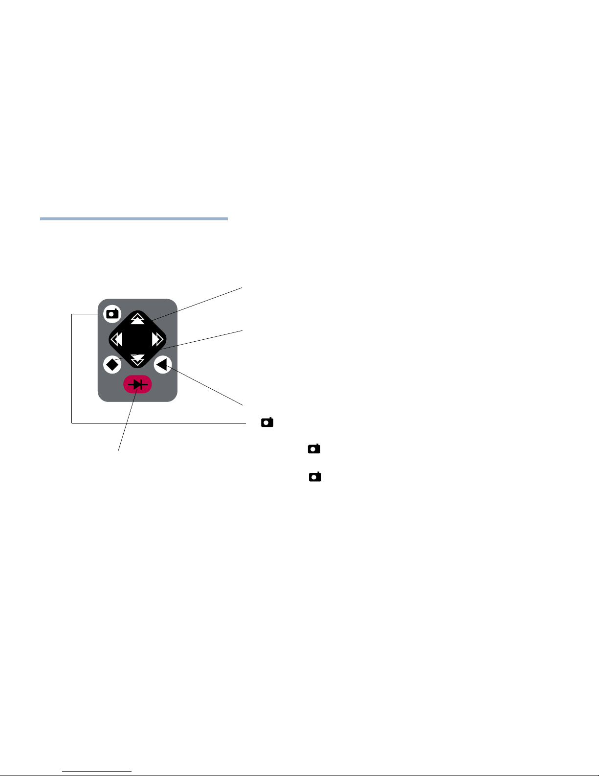
Using the controls and selecting options
To navigate around the various screens and select options a combination of keypad controls and
on-screen buttons are used.
Controls
The navigation controls are arranged up, down, left and right in the centre of the keypad. Their use
depends on the current screen and the screen item selected. Usually the left and right controls
change the current selection left or right and the up and down controls adjust levels (alarm levels,
power levels, etc.)
The control is primarily used to toggle between setting the sound volume and the current
selection. Sound volume can only be set on those screens that display the sound icon in the
DETECT and IDENTIFY modes (see under Setting the Unit volume in the DETECT mode section
of this manual)..
Note On those screens where setting the sound volume is not applicable, for
convenience, this control also duplicates the most common screen option.
The 3control is used to return back up to the parent screen of the current screen.
The p control is used in the IDENTIFY mode to pause the display and capture screen images for
later analysis.
Press p once to Pause the display
' >>> P a u s e d <<< ' appears on the screen display
press p a second time to save a screen shot to the Snapshot Log
To cancel the Pause press the 3control.
Screen Options
The touch sensitive screen is used to select items in the main menu and choosing a detector in
the Detect screen as well as operating various screen buttons that appear at the bottom of the
screen.
The NLJD Trigger control is used to turn
the NLJD On or Off.
(See under Enabling /Disabling the NLJD
later in this manual).

12 AUDIOTEL INTERNATIONAL MN400872 Issue 1 (08/04)
DETECTIV User Manual
AUDIOTEL INTERNATIONAL MN400872 Issue 1 (08/04) 13
Setting time & date
From the Main menu select CONFIGURE by either:
Touch the CONFIGURE icon on the screen
or
use the Left and Right controls on the keypad to highlight the CONFIGURE icon, then
press the button to select.
The CONFIGURE screen is displayed.
The LEFT and RIGHT controls on the keypad move the highlight (underscore) between the digits
in the day/month/year/hour/minute display. The Up and Down controls increase (UP) or decrease
(DOWN) the number.
Highlight the digit you wish to change using the Left and Right controls
Increase or decrease the selected digit using the up and down controls.
Once the time and date is correct, touch the ACCEPT on-screen button to set the
time and date.
Your DETECTIV unit is now ready for use.

AUDIOTEL INTERNATIONAL MN400872 Issue 1 (08/04) 13
BASIC OPERATING METHODOLOGY
The basic operating method for using the DETECTIV follows three sequential steps.
DETECT
With the DETECTIV displaying either the Main menu or the Detect display (Select DETECT
from the main menu) move the DETECTIV unit around the area to be secured.
Note DETECTIV is intended to nd suspicious devices within a target area. To avoid
excessive interference the sensors are optimised to limit the range at which
devices are detected. To search effectively the search head needs to pass closely
to all possible hiding places.
The DETECT mode utilises all the DETECTIV detectors simultaneously and should ensure that,
as the unit search head is swept over areas of likely concealment, the opportunities for detecting
a target are maximised.
When a large response is noted from one or more of the detectors it can be investigated further
using the Identify features for the appropriate detector.
IDENTIFY
The IDENTIFY stage involves using the various tools built into each one of the DETECTIV
detectors to try and identify whether or not the detected response is a possible threat.
If it seems likely that the detected response is a threat then the unit can move into the LOCATE
mode.
LOCATE
The LOCATE stage involves moving the DETECTIV around the suspect area using both the
display and the audio output to locate the source of the detected response.

14 AUDIOTEL INTERNATIONAL MN400872 Issue 1 (08/04)
DETECTIV User Manual
AUDIOTEL INTERNATIONAL MN400872 Issue 1 (08/04) 15
From the Main menu select DETECT by either:
Touch the DETECT icon on the screen
or
use the Left and Right controls on the keypad to highlight the DETECT icon, then
press the button to select.
The DETECT screen is displayed.
This is the basic mode of operation for the DETECTIV unit. In this mode all four detectors
are active at the same time. Each detector is designed to detect a specic type of target and is
represented with a vertical bar graph which increases or decreases in height in relation to the
detected signal(s).
The detectors are divided into 2 groups: Transmitter detectors and Device detectors
Transmitter Detectors
On the left of the screen these detectors respond to active radio transmissions.
Broadband CW will respond to continuous transmissions both narrow band (e.g. analogue
‘bug’) and broadband continuous transmissions (e.g. analogue video
transmissions)
Broadband Burst will respond to intermittent or burst transmissions (e.g. digital mobile
phones or frequency hopping devices)
Note because these two detectors are broadband in nature they only
indicate the strongest signal detected.
Harmonic Receiver will respond to continuous transmissions with better sensitivity than the
Broadband detectors, the harmonic receiver will also have the ability to
cancel out background signals and allow signals other than the strongest
signal to be captured.
DETECT MODE
DETECT mode icon
Detector selection
Indicator bar graphs
Sound Volume (see under
setting the unit Volume)
Snapshot counter
Harmonic receiver
mode indicator
Alarm icons
appear here
IDENTIFY mode button
LOCATE mode button

AUDIOTEL INTERNATIONAL MN400872 Issue 1 (08/04) 15
Device Detectors
On the right of the screen these two detectors respond to electronic devices whether they are
active or inactive.
Metal detector will respond to inactive well screened metal targets with a reasonable cross
sectional area (6cm x 6cm) at a range of approx. 10cm through brick and
CELCON block.
NLJD will respond to electronic targets (active / inactive) provided they are not
well screened against the NLJD signals. The Bar graph display shows both
2nd (red) and 3rd (green) harmonic return signals
Selecting a Detector
To select a detector, either
Touch the relevant detector icon on the screen
or
use the Left and Right controls on the keypad to highlight the relevant detector icon.
The currently selected detector is identied in the upper part of the DETECT screen and
highlighted by a RED box around the detector icon.

16 AUDIOTEL INTERNATIONAL MN400872 Issue 1 (08/04)
DETECTIV User Manual
AUDIOTEL INTERNATIONAL MN400872 Issue 1 (08/04) 17
Setting the unit Volume
The audio output in the DETECT screen is a form of ‘Geiger’ click which rises and falls in pitch in
relation with the level of the currently selected detector bar graph.
The sound icon is displayed towards the upper right corner of the screen in all screens of DETECT,
IDENTIFY or LOCATE modes. The sound volume can only be adjusted when this icon is displayed.
To adjust the sound volume
press the control on the keypad.
The sound volume indicator next to the sound icon is highlighted with a RED selection box.
Use the LEFT and RIGHT controls to decrease or increase the unit VOLUME.
Pressing any on-screen selection will automatically deselect the sound selection.
Alternatively press the control to deselect the sound selection.
Transmitter Detector Alarms
The transmitter detector bar graphs include alarm thresholds. These are indicated as red bars
across the vertical bar graphs.
To set an alarm threshold:
select the relevant transmitter detector
Use the UP and DOWN controls on the keypad to increase or decrease the alarm
threshold.

AUDIOTEL INTERNATIONAL MN400872 Issue 1 (08/04) 17
When the level for any of the transmitter detectors exceeds the corresponding alarm threshold
the relevant bar graph will turn RED for approx. 5 seconds, this is accompanied by the alarm icon
for the relevant detector also being displayed in the top right hand corner of the screen also for
approx. 5 seconds.
If a multimedia card has been installed (see under Multi-media memory card in the Getting Started
part of this manual ) a time and date stamped entry of the alarm is also automatically registered in
the EVENT LOG (see the Event Log section later in this manual for further details).
NLJD Display
The NLJD bar graph shows two bars. These indicate the return signals received at the 2nd and
3rd harmonic frequencies.
The red bar indicates the 2nd harmonic signal and
the green bar shows the 3rd harmonic signal. The relative strengths of these two returns is used
as an indicator of the type of Non-Linear junction being detected.
Enabling / Disabling the NLJD
The TRIGGER control can be used to enable / disable the NLJD in both the DETECT screen and
the NLJD IDENTIFY screen.
To enable / disable the NLJD detector
Press the Trig control on the keypad.
When the NLJD is disabled the NLJD bar graph is ‘greyed’ out.
signal below threshold:
Bar remains Green.
signal above threshold:
Bar turns Red and relevant
alarm icon displayed.

18 AUDIOTEL INTERNATIONAL MN400872 Issue 1 (08/04)
DETECTIV User Manual
AUDIOTEL INTERNATIONAL MN400872 Issue 1 (08/04) 19
IDENTIFY MODE
This mode is used to positively identify a suspect signal as
a potential eavesdropping device within the search area.
To select the IDENTIFY mode
From the Detect screen
select the appropriate detector
press the IDENTIFY on-screen button.
The IDENTIFY screen for the selected detector is displayed.
Broadband CW Identify screen
The Broadband CW Identify screen shows a scrolling display of received broadband signal
strength against time.
The time scale can be changed using the Zoom In and Zoom Out on-screen buttons.
This increases or decreases the rate at which the display scrolls.
The audio output in this mode is broadband AM (Amplitude Modulation).
Alarm thresholds remain active in this mode and can be adjusted using the up and
Down controls.
When the alarm threshold is exceeded the appropriate alarm icon is displayed in the top right hand
corner of the display and an entry is made in the EVENT LOG.
time
signal strength
alarm threshold

AUDIOTEL INTERNATIONAL MN400872 Issue 1 (08/04) 19
Broadband Burst IDENTIFY screen
The Broadband Burst Identify screen is very similar to the Broadband CW Identify screen, and also
shows an oscilloscope type of display of received broadband burst signal strength against time.
The time scale can be changed using the Zoom In and Zoom Out on-screen buttons.
This increases or decreases the rate at which the display scrolls.
The audio output in this mode is broadband AM.
Alarm thresholds remain active in this mode and can be adjusted using the up and
Down controls.
When the alarm threshold is exceeded the appropriate alarm icon is displayed in the top right hand
corner of the display and an entry is made in the EVENT LOG.
In addition this mode also compares the received signals against a library of known signal
signatures. If the signal is recognised the signal type (e.g.: GSM) is also displayed in the top left
hand side of the screen.

20 AUDIOTEL INTERNATIONAL MN400872 Issue 1 (08/04)
DETECTIV User Manual
AUDIOTEL INTERNATIONAL MN400872 Issue 1 (08/04) 21
Harmonic Receiver IDENTIFY screen
The Harmonic Receiver Identify screen displays the radio frequency spectrum in a compressed
form.
To change the span of the Spectrum displayed use the Zoom In and Zoom Out on-
screen buttons.
The current zoom level is indicated in the upper part of the screen above the spectral display.
As in the broadband Identify screens the Alarm thresholds remain active
Listening to a captured radio signal - Auto Tuning
When Auto Tune is selected the cursor (and hence the listening receiver) is automatically tuned to
the highest level signal on the screen.
To turn Auto tuning On or Off press the Auto Tune on-screen buttons.
Auto tune is ON when the button appears down (the Auto Tune text appears black)
and the tuning cursor is displayed in blue.
Note Manual tuning is inactive in Auto Tune.
Manual Tuning
The audio output for the Harmonic Receiver Identify stage is FM (Frequency Modulation). The
actual signal being listened to is identied with green tuning cursor cross-hairs.
To select a particular signal to listen to either:
Touch the display screen on the required signal peak
or
Use the LEFT and RIGHT controls to move the cursor left or right respectively.
The cursor can also be dragged using a nger to drag across the touch screen
Note: The harmonic receiver captures the RF spectrum (10MHz to 10GHz) in four bands
(approx. 2.5GHz wide), therefore when scanning rapid clicking will be heard as the
receiver switches through the bands in sequence.

AUDIOTEL INTERNATIONAL MN400872 Issue 1 (08/04) 21
To improve the audio quality of a captured radio signal press the P control on the
keypad to pause the receiver.
This pauses the receiver on the band of the captured signal. The background clicking
will know cease and the audio quality will improve.
Scanning in DIFFERENCE mode
The Diff On on-screen button selects and deselects the Difference mode.
Difference mode is ON when the Diff On button appears down (the Diff On text
appears black) .
When Difference mode is selected the current scan display is stored as a reference scan, all
subsequent scans are compared with this reference scan and the differences between the two
are displayed. This allows the user to take a scan of background RF activity prior to entering the
target area and effectively cancelling out background signals from the display. This will help in
highlighting signals peculiar to the target area that will require investigation.
Previous scans from a target area can also be used as reference scans allowing changes in RF
activity between sweeps to be highlighted quickly. These stored reference scans are captured
when the p control is used and held in the EVENT LOG - reference list. Uploading stored scans
is covered later in this manual in the EVENT LOG section.
Measuring a signal frequency
Note This facility is only available in Spectrum mode with Auto Tune selected.
To measure the frequency of a captured radio signal
Press the p control on the keypad.
This pauses the display and also attempts to measure the real RF frequency of the signal
indicated by the blue cursor cross-hairs.
The value is displayed above the main spectrum display.
Note DETECTIV takes four measurements. The result is only displayed if a
consistent result is obtained in three of the four attempts.

22 AUDIOTEL INTERNATIONAL MN400872 Issue 1 (08/04)
DETECTIV User Manual
AUDIOTEL INTERNATIONAL MN400872 Issue 1 (08/04) 23
NLJD & Metal Detector IDENTIFY screen
The NLJD and Metal Detector IDENTIFY modes share the same IDENTIFY screen; this shows a
number of indicator bars representing the following information:
m This is the returned signal strength for the Metal Detector.
CMP Compare shows a comparison of the second (2nd) and third (3rd) harmonic
return signals by subtracting the 3rd harmonic signal strength from the 2nd
harmonic signal strength.
2nd The 2nd harmonic signal strength.
3rd The 3rd harmonic signal strength.
Tx The transmitter signal power.
The audio output is a ‘Geiger’ click that rises and lowers in pitch in relation with the currently
selected bar indicator (the current indicator bar is highlighted with a red box).
The current selection can be adjusted by either:
Touch the required indicator bar name on the screen
or
use the Left and Right controls on the keypad to highlight the indicator bar name.
To Change NLJD TX power
select the Tx indicator bar
using the UP and DOWN controls on the keypad to increase or decrease the power
setting.

AUDIOTEL INTERNATIONAL MN400872 Issue 1 (08/04) 23
Changing the NLJD frequency
The operating frequency for an NLJD is specied by various approval bodies to minimise
interference between different users of the RF spectrum. Depending on the country of operation
one of these
CE versions of the DETECTIV will operate on a frequency of 869.6MHz
FCC versions of the DETECTIV will operate in the frequency band 902MHz
to 928MHz (frequency hopping).
Where approvals allow it is possible to change the NLJD TX frequency to any channel in the range
830MHz to 1000MHz in 100khz steps.
Press the Mode CE button to reveal a Freq Tune button.
Press the Freq Tune once
The red selection box highlights the NLJD TX frequency displayed at the top of the screen in MHz.
Move the underline highlight to the required digit using the LEFT and RIGHT keypad
controls
Use the UP and DOWN keypad controls to change the Tx frequency up and down.
Press the Freq Tune button a second time to set the changed Tx frequency.
The red box highlight is returned to the previous current selection.
Note: Adjusting the NLJD TX frequency can be used to avoid interference, it has also
proved useful for defeating ltering and screening on certain types of mobile
phones.
Note It is the operators responsibility to operate equipment only on those frequencies
licensed to them.

24 AUDIOTEL INTERNATIONAL MN400872 Issue 1 (08/04)
DETECTIV User Manual
AUDIOTEL INTERNATIONAL MN400872 Issue 1 (08/04) 25
Analysing the harmonic returns from targets
When either the 2nd or 3rd harmonic indicator bars are selected on the IDENTIFY screen the
Analyse on-screen button is displayed.
Press the Analyse button to display the NLJD analyse screen.
The analyse screen shows the spectral response of the 2nd and 3rd harmonic returns from any
target detected.
The 2nd harmonic should appear between the red vertical lines and
the 3rd harmonic should appear between the green vertical lines.
Also included on this screen is an offset cursor which allows the real frequency of any sidebands
returned on the harmonics to be measured.
The appearance of sidebands in the return signals may be caused by some active electronic
targets, the offset would be equal to internal clock frequencies within the target.
If a noisy return spectrum is noted this may be caused by some metal targets.

AUDIOTEL INTERNATIONAL MN400872 Issue 1 (08/04) 25
To select the LOCATE mode
From the Detect screen
select the appropriate detector
press the LOCATE on-screen button.
The LOCATE screen for the selected detector is displayed.
The audio output in this mode is a ‘Geiger’ click which increases in pitch in relation to the selected
detectors output
Broadband detector LOCATE screens
Harmonic detector LOCATE screen
Device detector LOCATE screens
LOCATE MODE
The LOCATE mode presents a simple display of detector
signal against time. The search head will be closest to the
target when the display indicates the highest peak.
time
signal strength

26 AUDIOTEL INTERNATIONAL MN400872 Issue 1 (08/04)
DETECTIV User Manual
AUDIOTEL INTERNATIONAL MN400872 Issue 1 (08/04) 27
EVENT LOG
To Select the EVENT LOG.
From the Main menu select LOG by either:
Touch the LOG icon on the screen
or
use the Left and Right controls on the keypad to highlight the LOG icon, then press
the button to select.
The EVENT LOG screen is displayed.
The EVENT LOG holds details of Alarms, screen Snapshots and Reference spectrums. These are
stored in three separate lists within the EVENT LOG. The currently selected list is indicated by the
red highlight box at the top of the screen.
Each log entry has an identifying code, as well as the date and time of the entry. The code
consists of a two letter code indicating the detector which generated the entry and a 2-digit
sequential number.
Note For accurate date and time details the user must have set the correct time and
date in the Cong screen (see under setting time and date earlier in this manual).
Use the LEFT and RIGHT keypad controls to move the red highlight to the required
event list.
Use the Up and Down keypad controls to select a specic entry in a list.
Each event log list presents four on-screen buttons with the following functions:
View Displays the currently selected log entry
Delete Deletes the currently selected log entry.
Empty Deletes the entire list for the log type currently being viewed (Alarm,
Snapshot or Reference)
Item / Page Switches the Up and Down keypad function between scrolling an Item at a
time or a Page at a time
Log entry codes
CW - Broadband CW
BB - Broadband burst
HA - Harmonic receiver

AUDIOTEL INTERNATIONAL MN400872 Issue 1 (08/04) 27
Alarms
Entries in the Alarm list are generated automatically each time a signal exceeds an alarm threshold
as set in either the DETECT or IDENTIFY modes.
Snapshots
Entries in the Snapshot log are generated each time a snapshot is taken of the screen by using
the p control on the keypad (for further details using the p key see under Using the
Controls and selecting options earlier in this manual)

28 AUDIOTEL INTERNATIONAL MN400872 Issue 1 (08/04)
DETECTIV User Manual
AUDIOTEL INTERNATIONAL MN400872 Issue 1 (08/04) 29
References
Entries in the reference log are created by using the p control in the Harmonic receiver
IDENTIFY screen.
To load a reference scan
Select the required reference scan from the reference log list
Press View to display the reference scan
The reference log view screen presents two on-screen buttons.
Load Press this button to load the displayed reference scan into the DETECTIV
Harmonic Receiver. The DETECT mode is automatically selected and
displayed.
Unload Press this button to unload a reference scan currently being used by the
Harmonic Receiver.
Note: This does NOT delete the reference scan from the Reference Log.

AUDIOTEL INTERNATIONAL MN400872 Issue 1 (08/04) 29
CONNECTION, DOWNLOAD TO A PC
Connecting DETECTIV to a PC
DETECTIV is connected to a PC via the USB port.
Once the PC and DETECTIV are physically connected with a suitable USB cable the EVENT
Log contents can be downloaded and viewed using the DETECTIV Viewer software.
To load the DetectIV Viewer software
insert the DETECTIV Viewer software CD and follow the on screen instructions.
DetectIV Viewer
The DETECTIV Viewer allows the user to, download, view and edit the various EVENT Logs
from a connected DETECTIV unit. An example of the main screen is shown below.
For details of use and operation please consult the complete on-line help supplied as part of the
software.

30 AUDIOTEL INTERNATIONAL MN400872 Issue 1 (08/04)
DETECTIV User Manual
AUDIOTEL INTERNATIONAL MN400872 Issue 1 (08/04) 31
ACCESSORY
To Select the Accessory Screen.
From the Main menu select Acc. by either:
Touch the Acc. icon on the screen
or
use the Left and Right controls on the keypad to highlight the Acc . icon, then press
the button to select.
The Accessory screen is displayed.
This screen is intended for use with future external detector accessories.
The screen shows the RF spectrum present on the accessory port between 10KHz and 12.8 MHz.
To change the span of the Spectrum displayed use the Zoom In and Zoom Out on-
screen buttons.
The current zoom level is indicated in the upper part of the screen above the spectral display.
Listening to a captured signal - Auto Tuning
When Auto Tune is selected the cursor (and hence the listening receiver) is automatically tuned to
the highest level signal on the screen.
To turn Auto tuning On or Off press the Auto Tune on-screen buttons.
Auto tune is ON when the button appears down (the Auto Tune text appears black)
and the tuning cursor is displayed in blue.
Note Manual tuning is inactive in Auto Tune.
Manual Tuning
The audio output for the Accessory screen is FM (Frequency Modulation). The actual signal being
listened to is identied with green tuning cursor cross-hairs. The real frequency of the signal at
that position is indicated at the top of the screen as the Marker frequency.

AUDIOTEL INTERNATIONAL MN400872 Issue 1 (08/04) 31
To select a particular signal to listen to either:
Touch the display screen on the required signal peak
or
Use the LEFT and RIGHT controls to move the cursor left or right respectively.
The cursor can also be dragged using a nger to drag across the touch screen

32 AUDIOTEL INTERNATIONAL MN400872 Issue 1 (08/04)
DETECTIV User Manual
AUDIOTEL INTERNATIONAL MN400872 Issue 1 (08/04) 33
Battery compartment
AC/DC power socketMemory card slot
USB port
Accessory port
APPENDIX A - BATTERY & I/O

AUDIOTEL INTERNATIONAL MN400872 Issue 1 (08/04) 33
APPENDIX B - MENU STRUCTURE
Main menu
DETECT screen EVENT logs
CONFIGure
screen
ACCcessory
screen
LOCATE screens
IDENTIFY screens

DETECTIV User Manual - MN400782 Issue 1 (08/04)
© 2004 Audiotel International Ltd.
 Loading...