

Audio Technica unipoint U891RC Specifications
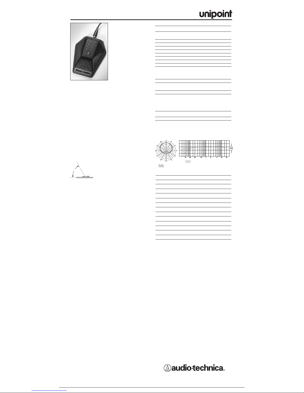
• Designed for surface-mount
applications such as highquality sound reinforcement,
conferencing, distance
learning and other demanding
sound pic
kup situations
• Ultra-quiet electronic switch
can be set to any of three
operating modes:
“touch-on/touch-off,”
“touch-to-talk” and
“touch-to-mute”
• External contact closure
capability permits control of
remote devices from
microphone switch
• External LED control allows for
accurate depiction of the live
status of the microphone
• PivotPoint
™
rotating output connector allows cable to exit from
either the rear or the bottom of the microphone
• Small-diameter UniPoint capsule near boundary eliminates phase
distortion and delivers clear, high-output performance
• UniGuard
™
RFI-shielding technology offers outstanding rejection
of radio frequency interference (RFI)
• Heavy die-cast case and non-slip silicon foam bottom pads
minimize coupling of surface vibration to the microphone
• Low-profile design with low-reflectance black finish for minimum
visibility
The U891RC requires 11V to 52V phantom power for operation.
Supplied as a cardioid, the U891RC accepts interchangeable
elements to per
mit selection of angle of acceptance from 100° to
360°.
The electronics in the microphone tak
e up to 30 seconds to stabilize
after power is applied; during this start-up period, some sonic
disturbances may be heard upon switching if the system is “live.”
The microphone should be placed on a flat, unobstructed mounting
surface, with the front of the microphone facing the sound source.
The sound source should not be belo
w, or higher than 60° above,
the plane of the mounting surface.
The U891RC features a touch-sensitive on/off
switch, indicator LED and external contact
closure ability for controlling remote devices.
The touch switch can be configured for touchon/touch-off, momentary on (“press to talk”),
or momentary off (“press to mute”). Slide the
switch marked “SW. FUNCTION” (located on
the bottom of the microphone) to the appropriate mode. The
indicator LED and external contact closure follow the operation of
the touch switch, when in the local mode.
For applications that require the microphone to remain active or
always “on”, regardless of the touch switch setting, a “Local/Remote/
LED Remote” control function is provided.
•
When the switch marked “CONTROL” (located on the bottom of
the microphone) is in the “Local” position, the touch switch
controls the microphone's audio output, LED status and contact
closure internally.
•
When the “CONTROL” switch is in the “Remote” position, the
microphone's audio output remains active or “on” all the time.
The touch switch controls only the LED and contact closure.
• When the “CONTROL” switch is in the “LED remote” position, it
allows remote control of the LED, for accurate depiction of the
microphone's liv
e status. The LED will remain “on” when driven
logic high or open, and “off” when driven logic low or connected to
ground. The microphone's audio output remains active or “on” all
the time
, and the contact closure follows the configuration of the
touch switch
*Ref
er to the table at the right for switch/LED/closure states.
Output is low impedance balanced. The signal appears across the
red and y
ellow wires; audio ground is the shield connection. Output
is phased so that positive acoustic pressure produces positive
v
oltage on the yellow wire. The small-diameter black and blue wires
are the contact closure. The white wire is the external LED control.
An integral 80 Hz high-pass filter provides easy switching from a flat
frequency response to a low-end roll-off. The roll-off position
reduces the pickup of low-frequency ambient noise (such as traffic,
air-handling systems, etc.), room reverberation and mechanically
coupled vibrations.
Avoid leaving the microphone in the open sun or in areas where
temperatures exceed 110° F (43° C) for extended periods.
Extremely high humidity should also be avoided.
NOTE: Audio-Technica has developed a special RFI-shielding
mechanism, which is an integral part of the connectors in the
UniP
oint line. If you remove or replace the connector, you may
adversely affect the unit's RFI immunity.
NOTE: Placing any object on a surface (such as a conference table)
before its finish is fully cured may result in damage to the finish.
8 kHz
Polar Pattern
SCALE IS 5 DECIBELS PER DIVISION
LEGEND
200 Hz
1 kHz
5 kHz
Frequency in Hertz
LEGEND
12" or more on axis
Roll-off
Frequency Response
Response in dB
Audio-Technica U.S., Inc., 1221 Commerce Drive, Stow, Ohio 44224
Audio-Technica Limited, Old Lane, Leeds LS11 8AG England
www
.audio-technica.com
P51704 ©2005 Audio-Technica U.S., Inc. Printed in U.S.A.
U
891RC
U891RC SPECIFICATIONS
†
ELEMENT Fixed-charge back plate
permanently polarized condenser
POLAR PATTERN Half-cardioid
(cardioid in hemisphere above
mounting surface)
FREQ
UENCY RESPONSE
30-20,000 Hz
LO
W FREQUENCY ROLL-OFF
80 Hz, 18 dB/octa
ve
OPEN CIRCUIT SENSITIVITY –34 dB (19.9 mV) re 1V at 1 P
a*
IMPED
ANCE
200 ohms
MAXIMUM INPUT SOUND LEVEL 130 dB SPL, 1 kHz at 1% T.H.D.
DYNAMIC RANGE (typical) 104 dB, 1 kHz at Max SPL
SIGNAL-TO-NOISE RATIO
1
68 dB, 1 kHz at 1 Pa*
PHANT
OM POWER REQUIREMENTS
11-52V DC
, 4 mA typical
SWITCHES T
ouch-sensitive control: on/off;
Switch function:
touch on/off,
momentar
y on, momentary off;
Control:
local, remote, LED remote;
Flat, roll-off
WEIGHT 9.4 oz (266 g)
DIMENSIONS 4.25" (108.0 mm) long,
3.31" (84.0 mm) maximum width,
0.91" (23.0 mm) height
OUTPUT CONNECTOR TB5M-type
CABLE 25,0' (7.6 m) long, 0.13" (3.2 mm)
diameter, 5-conductor shielded cable
(2 conductors under shield; 3 control
wires outside shield); TA5F-type
connector at microphone end, output
end stripped and tinned for
connection to electronic device
OPTIONAL INTERCHANGEABLE UE-H h
ypercardioid (100°);
ELEMENTS UE-O omnidirectional (360
°)
A
CCESSORY FURNISHED
Soft protectiv
e pouch
†
In the interest of standards development, A.T.U.S.offers full details on its test
methods to other industry professionals on request.
*1 Pascal = 10 dynes/cm
2
= 10 microbars = 94 dB SPL
1
Typical, A-weighted, using Audio Precision System One.
Specifications are subject to change without notice.
CARDIOID CONDENSER BOUNDARY
MICROPHONE WITH LOCAL OR REMOTE SWITCHING
CONTROL Switch in “Local”Position
SW Setting Microphone Audio LED External Contact
Closure
T
OUCH ON/OFF Follows touch- Follows touch- Follows touch-
sensitive switch sensitive switch sensitive switch
MOM. ON “On” when switch “On” when switch Closed when switch
is pressed is pressed is pressed
MOM. OFF “Off ”when switch “Off” when switch Open when switch
is pressed is pressed is pressed
CONTROL Switch in “Remote”Position
SW Setting
Microphone Audio LED External Contact
Closure
TOUCH ON/OFF Always “On” Follows touch- Follows touch-
sensitive switch sensitive switch
MOM. ON Always “On” “On” when switch Closed when switch
is pressed
is pressed
MOM. OFF Always “On” “Off” when switch Open when switch
is pressed is pressed
CONTROL Switch in “LED Remote”Position
SW Setting Microphone Audio LED External Contact
Closure
T
OUCH ON/OFF Always “On” Remotely controlled Follows touch-
sensitive switch
MOM. ON Always “On” Remotely controlled Closed when switch
is pressed
MOM.
OFF Always “On” Remotely controlled Open when switch
is pressed
60°
IDEAL
WORKING
ANGLE
 Loading...