

Audio Technica unipoint U857QLU, unipoint U857QU Specifications
• Designed for high-quality
sound reinforcement,
professional recording and
broadcasting
• UniLine
™
polar pattern
provides narrow 90°
acceptance angle
• Superior off-axis rejection for
maximum gain before
feedback
• UniGuard
™
RFI-shielding
technology offers outstanding
rejection of radio frequency
interference (RFI)
• Easy-to-adjust, rugged,
small-diameter, alternating
gooseneck with virtually no
“memory” permits quick
positioning into desired shape
• UniSteep
®
filter provides a
steep low-frequency
attenuation to improve sound
pickup without affecting voice
quality
• Self-contained electronics eliminate need for external power
module
• Accepts interchangeable elements to permit angle of
acceptance from 90° to 360°
• Two-stage foam windscreen yields dramatically improved
resistance to P-pops and other breath blasts
• Quick-mount design with 3-pin XLRM-type connector insert at
base plugs into any standard XLRF-type surface or cable
connector
•
Included shock mount attenuates noise, shock and vibration
transmitted through the mounting surface
The U857QU stands 19.17" (487.0 mm) from the table or podium; it
is also available in a 23.74" (603.0 mm) version as U857QLU. The
two models are identical in all other respects.
The U857QU requires 11V to 52V phantom power for operation.
Output from the microphone’s XLRM-type connector is low
impedance (Lo-Z) balanced. The signal appears across Pins 2 and
3; Pin 1 is ground (shield). Output phase is “Pin 2 hot” – positive
acoustic pressure produces positive voltage at Pin 2.
An integral 80 Hz high-pass UniSteep
®
filter provides easy
switching from a flat frequency response to a low-end roll-off. The
roll-off position reduces the microphone’s sensitivity to popping
in close vocal use. It also reduces the pickup of low-frequency
ambient noise (such as traffic, air-handling systems, etc.), room
reverberation and mechanically coupled vibrations.
A
void leaving the microphone in the open sun or in areas where
temperatures exceed 110° F (43° C) for extended periods.
Extremely high humidity should also be avoided.
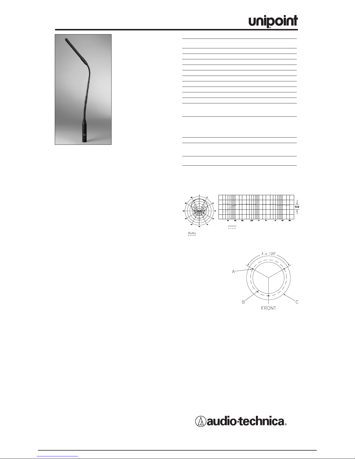
8 kHz
Polar Pattern
SCALE IS 5 DECIBELS PER DIVISION
LEGEND
200 Hz
1 kHz
5 kHz
F
requency in Hertz
LEGEND
12" or more on axis
Roll-off
Frequency Response
Response in dB
Audio-Technica U.S., Inc., 1221 Commerce Drive, Stow, Ohio 44224
Audio-Technica Limited, Old Lane, Leeds LS11 8AG England
www.audio-technica.com
P51692 ©2005 Audi
o-Technica U.S., Inc. Printed in U.S.A.
U857QU/U857QLU
U857QU/ U857QLU SPECIFICATIONS
†
ELEMENT Fixed-charge back plate
per
manently polarized condenser
POLAR P
ATTERN
Line Cardioid
FREQ
UENCY RESPONSE
30-20,000 Hz
LO
W FREQUENCY ROLL-OFF
80 Hz, 18 dB/octa
ve
OPEN CIRCUIT SENSITIVITY –35 dB (17.7 mV) re 1V at 1 Pa*
IMPED
ANCE
250 ohms
MAXIMUM INPUT SOUND LEVEL 135 dB SPL, 1 kHz at 1%
T.H.D.
D
YNAMIC RANGE
(typical)
115 dB, 1 kHz at Max SPL
SIGNAL-TO-NOISE RATIO
1
74 dB, 1 kHz at 1 Pa*
PHANT
OM POWER REQUIREMENTS
11-52V DC
, 2 mA typical
SWITCH Flat, roll-off
WEIGHT
U857Q
U
5.7 oz (161 g)
U857QLU 5.9 oz (167 g)
DIMENSIONS
U857Q
U
19.17" (487.0 mm) long
U857QLU 23.74" (603.0 mm) long
BO
TH
0.48" (12.2 mm) head diameter
,
0.74 (18.9 mm) base diameter
OUTPUT CONNECT
OR
Integ
ral 3-pin XLRM-type
OPTIONAL INTERCHANGEABLE UE-C cardioid (120°);
ELEMENTS UE-H h
ypercardioid (100°);
UE-O omnidirectional (360
°)
A
CCESSORIES FURNISHED
A
T8154 two-stage foam
windscreen;
AT8662 shock mount
†
In the interest of standards development, A.T.U.S. offers full details on its test
methods to other industr
y professionals on request.
*1 Pascal = 10 dynes/cm
2
= 10 microbars = 94 dB SPL
1
Typical, A-weighted, using Audio Precision System One.
Specifications are subject to change without notice
.
UNILINE™CONDENSER QUICK-MOUNT
GOOSENECK MICROPHONES
Shock Mount Installation
AT8662 mounting dimensions
A.1/16" (1.5 mm) pilot
holes 3 places on
2.29" (58.2 mm) circle.
B. 2.0" (51.0 mm)
through-hole for mount
clearance
C. Outside edge of
flange, 2.79"
(71.0 mm) diameter
Drawing not actual size.
1. Find the center of the mounting location and mark it. Allow
enough clearance to accommodate the shock mount's flange
on the surface and make certain there are no physical
obstructions below the desired location.
2. Using 2.0" (51.0 mm) hole saw, drill the large through-hole for
the shock mount.
3. Set the shock mount into the hole and mark the location of the
three mounting screw holes.
Make certain to “center” the
mount in the large hole before marking the three small
mounting screw locations.
4. Using a 1/16" (1.5 mm) drill bit, drill three pilot holes for the
mounting screws.
5.
After installing the microphone, assure maximum shock
mounting effectiveness by providing some slack in the
connecting cable.
 Loading...