

Audio Technica unipoint U853PMU, unipoint U853PMWU Specifications
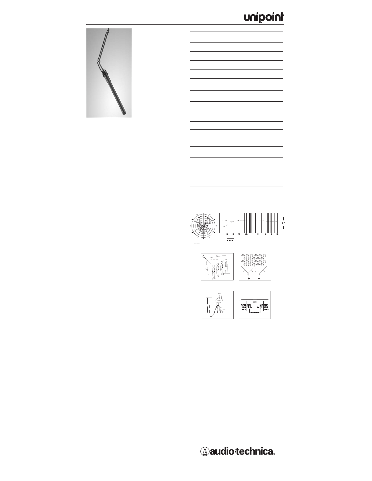
• Designed for suspension over
choirs, instrumental groups
and theater stages
• Wall/ceiling plate power module
per
mits permanent installation
in standard metal U.S. single
gang electrical box
• UniLine
™
polar pattern
provides narrow 90°
acceptance angle
• Superior off-axis rejection for
maximum gain before
feedback
• UniGuard
™
RFI-shielding
technology offers outstanding
rejection of radio frequency
interference (RFI)
• UniSteep
®
filter provides a
steep low-frequency
attenuation to improve sound
pickup without affecting voice
quality
• Accepts interchangeable elements to permit angle of acceptance
from 90° to 360°
• Low-profile design with low-reflectance finish for minimum
visibility
• Available in two colors:black (U853PMU) and white (U853PMWU)
The U853PMU requires 11V to 52V phantom power for operation.
A uniform 90° angle of acceptance provides well-balanced audio
pickup over a narrow area. The microphone should be located
forward of the front-most source, above the rear-most source, and
“aimed” between them (Fig.1). Increasing the height of the mic
above the sources will tend to equalize sound levels between them,
but may also increase background/reverberant sound pickup. When
possible, the distance from the mic to the rear-most source should
be no more than twice the distance to the front source, to maintain
front-to-rear balance (Fig. 1).
Width of pickup is approximately 1.5 times the distance to the
closest performer. If additional mics are needed for wide sources,
they should be positioned apart laterally at least 1.5 times the
distance to the front source, to avoid phase cancellation (Fig. 2).
To orient the microphone in the proper direction, twist the housing
slightly in its wire holder
. (Clockwise rotation moves the microphone
to the right; counterclockwise rotation moves it to the left.)
The wall/ceiling plate power module comes supplied with a TB3Mtype connector in place. Plug the microphone cable's TA3F
connector into the wall/ceiling plate power module's TB3M-type
connector. The power module features a white-finished standard
electrical cover plate for easy, secure installation.
The AT8534 wall/ceiling plate power module is designed to be
mounted in a standard metal U
.S. single-gang electrical box. For
safety and best performance, use the electrical box
only for the
AT8534; do not include any AC power conductors. (Also route the
mic cable as far away from AC power cables as possible.)
NOTE: Audio-Technica has developed a special RFI-shielding
mechanism, which is an integral part of the connectors in the
UniPoint line. If you remove or replace the connector, you may
adversely affect the unit's RFI immunity.
However, if you must change cable length, replace the TB3M-type
connector on the w
all/ceiling plate power module with the provided
strain relief. Feed the small cable from the mic through the strain
relief on the power module plate. Tie a loose knot in the cable at the
desired length and push it down gently into the recess in the back of
the strain relief to secure the microphone. Cut excess cable, strip the
mic cable wires (Fig. 3) and attach them to their respective input
terminals (Fig. 4).
Screw-terminal output connections of the AT8534 are the same as
those of an XLR-type plug: shield to Terminal 1, balanced single and
phantom po
wer to Terminals 2 and 3. Output is phased so that
positive acoustic pressure produces positive voltage at Terminal 2, in
accordance with industry convention.
Do not connect the output
cable shield to the box.
Double-check to make certain that all input
and output leads have no bare wires or loose strands that could
touch each other, the circuit board or the electrical box. Then attach
the power module plate to the electrical box.
An integral 80 Hz high-pass UniSteep
®
filter provides easy switching
from a flat frequency response to a low-end roll-off (switch located
on circuit board). The roll-off position reduces the pickup of lowfrequency ambient noise (such as traffic, air-handling systems, etc.),
room reverberation and mechanically coupled vibrations.
A 10 dB gain switch is provided for situations that demand extra
sensitive pickup. The +10 position increases the microphone's
overall output by 10 dB.
Avoid leaving the microphone in the open sun or in areas where
temperatures exceed 110° F (43° C) for extended periods.Extremely
high humidity should also be avoided.
8 kHz
Polar Pattern
SCALE IS 5 DECIBELS PER DIVISION
LEGEND
200 Hz
1 kHz
5 kHz
F
requency in Hertz
LEGEND
12" or more on axis
Roll-off
Frequency Response
Response in dB
Audio-Technica U.S., Inc., 1221 Commerce Drive, Stow, Ohio 44224
Audio-Technica Limited, Old Lane, Leeds LS11 8AG England
www.audio-technica.com
P51810 ©2005 Audio-Technica U.S., Inc. Printed in U.S.A.
U853PMU/U853PMWU
U853PMU/U853PMWU SPECIFICA
TIONS
†
ELEMENT Fix
ed-charge back plate
per
manently polarized
condenser
POLAR PATTERN Line Cardioid
FREQUENCY RESPONSE 30-20,000 Hz
LOW FREQUENCY ROLL-OFF 80 Hz, 18 dB/octave
OPEN CIRCUIT SENSITIVITY –35 dB (17.7 mV) re 1V at 1 Pa*
IMPED
ANCE
200 ohms
MAXIMUM INPUT SOUND LEVEL 124 dB SPL, 1 kHz at 1%
T.H.D.
D
YNAMIC RANGE
(typical)
102 dB, 1 kHz at Max SPL
SIGNAL-T
O-NOISE RATIO
1
72 dB
, 1 kHz at 1 Pa*
PHANT
OM POWER REQUIREMENTS
11-52V DC
, 4 mA typical
SWITCHES Flat, roll-off;
0 dB/+10 dB gain setting
WEIGHT
MICROPHONE
1.1 oz (30 g)
POWER MODULE 3.4 oz (97 g)
DIMENSIONS
MICR
OPHONE
6.14" (156.0 mm) long,
0.48" (12.2 mm) diameter
PO
WER MODULE
2.80" (71.0 mm)
W x
4.55" (115.5 mm) H x
1.42" (36.0 mm) D
OUTPUT CONNECT
OR
Scre
w terminals
(po
wer module)
CABLE 25' (7.6 m) long (permanently
attached to microphone),
0.13" (3.2 mm) diameter,
2-conductor, shielded cable
with TA3F-type connector
OPTIONAL INTERCHANGEABLE UE-C cardioid (120°);
ELEMENTS UE-H hypercardioid (100°);
UE-O omnidirectional (360
°)
A
CCESSORIES FURNISHED
U853PMU
A
T8154 two-stage foam
windscreen;
AT8451 steel hanger
U853PMWU A
T8154(WH) two-stage foam
windscreen;
AT8451(WH) steel
hanger
BOTH AT8534 wall/ceiling plate power
module; AT8438
5
/8"-27 stand
adapter
†In the interest of standards development, A.T.U.S.offers full details on its test
methods to other industry professionals on request.
*1 P
ascal = 10 dynes/cm
2
= 10 microbars = 94 dB SPL
1 Typical, A-weighted, using Audio Precision System One.
Specifications are subject to change without notice.
UNILINE™CONDENSER
HANGING MICROPHONES
LESS THAN 2 TIMES “X”
DIST
ANCE “X”
90°
ANGLE OF
ACCEPTANCE
Figure 1
MIC A
1.5 TIMES
DISTANCE “X”
MIC B
90°90°
Figure 2
Shield strands,
fully twisted
Y
ellow-Yellow
Red-Red
1
/8" strip reds
and yellows
1
/2"
1
"
Figure 3
Figure 4
 Loading...