

Audio Technica UniPlate AT891R, UniPlate AT891C Product Information
Architects and Engineers Specifications
The microphone shall be a fixed-charge
condenser with a unidirectional polar pattern
designed for use in surface-mount boundary
applications. The frequency response shall be
30 Hz to 15,000 Hz. The microphone shall
operate from an external 11V to 52V phantom
power source. Nominal open-circuit output
voltage shall be 17.7 mV at 1 kHz, 1 Pascal.
Output shall be low impedance balanced
(200 ohms).
The microphone shall have a touch-sensitive
switch that may be set to one of three operating
modes: touch-on/touch-off, momentary on, or
momentary off. An integral LED indicator and
contact closure shall follow the touch switch
operation. For applications requiring the
microphone to operate independently of the
touch switch, a “Local/Remote” mode shall be
provided. When the “Remote” mode is selected, the microphone audio output shall always
remain “on” regardless of the status of the
contact closure and LED. The microphone shall
include a switch to select low-frequency roll-off.
A 20' (6.1 m) unterminated cable shall be
supplied for connection between the
microphone and electronics input. The cable
shall be attached to the microphone via internal
screw terminals and shall have an unterminated
5-conductor output for connection to a variety of
electronics. The cable shall be configurable for
back- or bottom-of-mic exit. The microphone
shall have a maximum width of 2.87" (73.0 mm)
and a maximum length of 4.33" (110.0 m).
Weight shall be 5.8 oz (165 g). The
microphone shall be housed in a rugged case
with a two-layer perforated steel grille. Finish
shall be low-reflectance black.
The Audio-Technica AT891R/C is specified.
Description
The AT891R/C is a condenser boundary
microphone with a hemi-cardioid (half-space
cardioid) polar pattern. It features a touchsensitive on/off switch, indicator LED and
external contact closure ability for controlling
remote devices such as tally lights, camera
calls, speaker zones and other equipment. The
touch switch can be configured for touchon/touch-off, momentary on (“press to talk”), or
momentary off (“press to mute”). The indicator
LED and external contact closure follow the
operation of the touch switch.
A “Remote” mode enables the AT891R/C
microphone element to operate independently
of the touch switch, LED and contact closure.
This mode is ideal for applications such as
teleconferencing and video conferencing that
use echo cancellers and other processing
equipment, which often require continuous
audio from the microphone. The touch switch
and contact closure are used to mute the audio
within the external processing equipment,
rather than at the microphone itself.
The AT891R/C can be powered from any
external 11V to 52V DC phantom power supply.
A switch on the bottom of the unit permits
choice of flat response or low-frequency roll-off
to help control undesired ambient noise. A 20'
(6.1 m) unterminated cable is attached to the
microphone via internal screw terminals and can
be routed from either the back or the bottom of
the housing for maximum positioning flexibility.
The microphone is enclosed in a rugged case
and protected by two layers of perforated steel.
The rubber non-slip bottom pad minimizes
mechanical coupling of surface vibrations to the
microphone. The low-profile housing has a lowreflectance black finish.
Installation and Operation
The AT891R/C requires 11–52V phantom power,
which operates the microphone and switch
circuitry. The electronics in the microphone take
up to 30 seconds to stabilize after power is
applied; during this start-up period, some
thumps or other sonic disturbances may be
heard upon switching if the system is “live.”
The AT891R/C has a touch-sensitive switch
that can be configured to operate in three
modes: touch-on/touch-off (TOUCH ON/OFF),
momentary on (MOM. ON), or momentary off
(MOM. OFF). Slide the switch marked “SW.
FUNCTION” (located on the bottom of the
microphone) to the appropriate mode. Note that
only one mode can be active at a time.
For applications that require the microphone
to remain active regardless of the touch
switch function setting, a “Local/Remote”
control function is provided. When the switch
marked “CONTROL” (located on the bottom
of the microphone) is in the “Local” position,
the audio output is controlled internally by the
touch switch. When the “CONTROL” switch
is in the “Remote” position, the microphone
audio output will remain active or “on”
all the time. Refer to the table below for
switch/LED/closure states.
The microphone’s 20' (6.1 m) cable may be
attached to exit the microphone from either the
back or the bottom. (If you need to extend the
cable length, be certain to use the exact same
type of cable used on the microphone: the audio
signal should use two-conductor shielded cable,
and the three control wires should not be under
the audio shield.) The microphone comes with
the cable exiting at the back. To route the cable
from the bottom of the microphone, you will
need a very small (No. 0) Phillips screwdriver.
1. Partially loosen the screw in the center of
the microphone base; press up on the screw
head to loosen the grille assembly. Then
remove the screw.
2. If necessary, carefully push out the
perforated steel grille by gently pushing the
screwdriver through the two mounting holes
on the bottom. The grille and foam
windscreen should pop off easily.
3. To remove the wires from the screw
terminals, loosen the screws, and then
gently pull the wires out.
4. Untie the knot in the cable and pull it out
through the strain relief.
5. Remove the rubber strain relief from the
rear opening of the microphone.
6. Feed the cable through the hole in the
bottom of the microphone.
7. Leaving a little slack for connecting the
wires to the screw terminals, knot the cable
inside the microphone to prevent strain on
the connections. (Once the microphone has
been installed, secure the cable below the
mounting surface.)
8. Reconnect the wires to the screw terminals
using the labels as a guide [see Figure A].
9. Tighten the screws to secure the wires. Do
not use the rubber strain relief with the
bottom-exit configuration.
10.Replace the perforated steel grille (with
foam windscreen) and secure with screw.
11.Cover the rear hole with the provided plug.
Output is low impedance balanced. The
balanced signal appears across the red and
yellow wires, while audio ground is the shield
connection. Output is phased so that positive
acoustic pressure produces positive voltage on
the yellow wire.
The blue and white wires are the contact
closure. A black “ground” wire is provided to
maintain ground integrity when the contact
closure is connected to an external device.
When connecting the contact closure output to
other equipment, be careful not to exceed the
switch current and voltage ratings outlined in
the specifications.
While a modern condenser microphone is
not unduly sensitive to the environment,
temperature extremes can be harmful. Avoid
leaving the microphone in the open sun
or in areas where temperatures exceed
110 degrees F (43 degrees C) for long periods
of time. Extremely high humidity should also be
avoided.
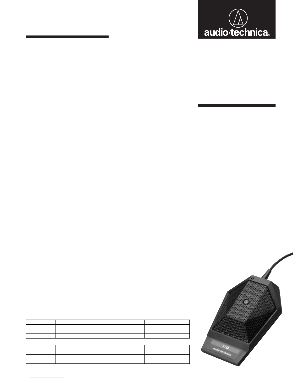
AT891R/C
UNIDIRECTIONAL
CONDENSER
BOUNDARY
MICROPHONE
WITH LOCAL OR
REMOTE SWITCHING
UniPlate
CONTROL Switch in “Local” Position
SW Function Microphone Audio LED External Contact Closure
TOUCH ON/OFF Follows switch function Follows switch function Follows switch function
MOM. ON “On” when switch is pressed “On” when switch is pressed Closed when switch is pressed
MOM. OFF “Off” when switch is pressed “Off” when switch is pressed Open when switch is pressed
CONTROL Switch in “Remote” Position
SW Function Microphone Audio LED External Contact Closure
TOUCH ON/OFF Always “On” Follows switch function Follows switch function
MOM. ON Always “On” “On” when switch is pressed Closed when switch is pressed
MOM. OFF Always “On” “Off” when switch is pressed Open when switch is pressed
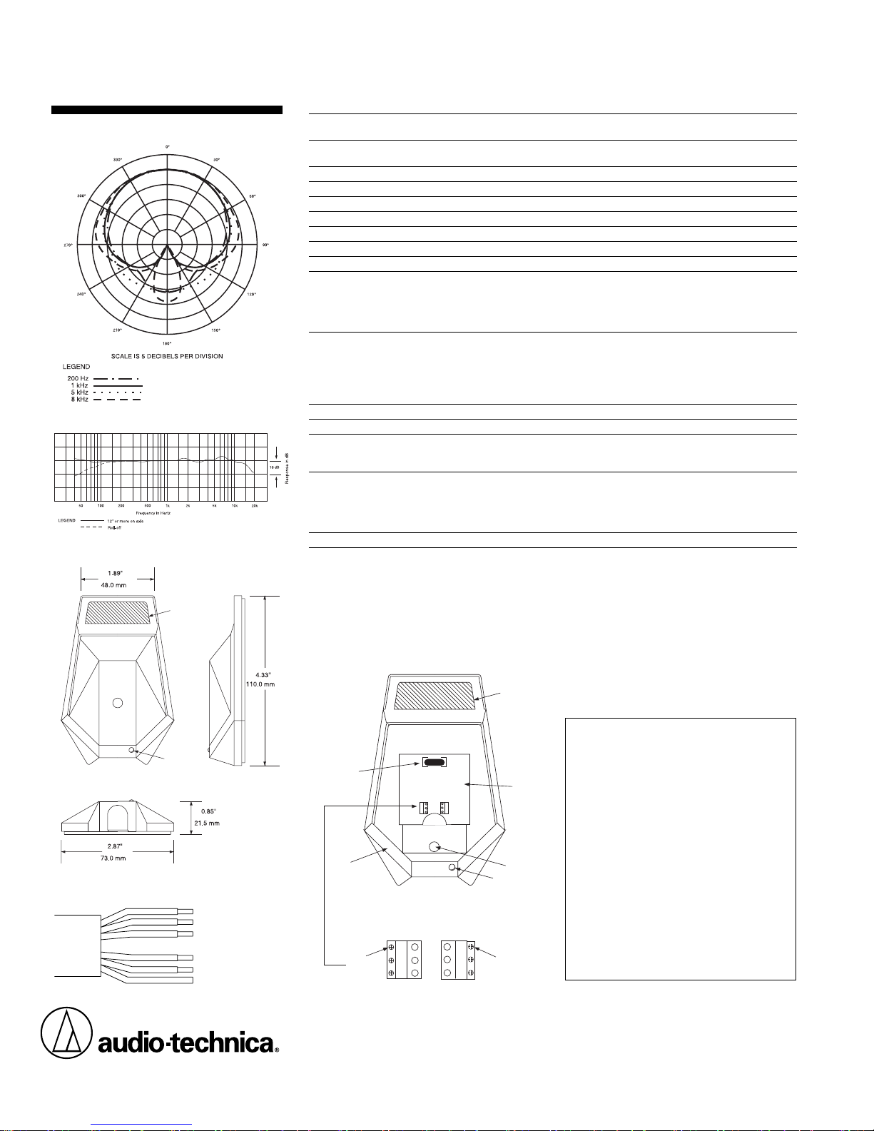
AT891R/C
Polar Pattern
Dimensions
Audio-Technica U.S., Inc., 1221 Commerce Drive, Stow, Ohio 44224
Audio-Technica Limited, Old Lane, Leeds LS11 8AG England
Form No. 0310-0866-00 P51607 © 2003 Audio-Technica U.S., Inc. Printed in U.S.A.
LED
Touch Switch
AT891R/C SPECIFICATIONS
†
ELEMENT Fixed-charge back plate
permanently polarized condenser
POLAR PATTERN Half-cardioid (cardioid in hemisphere above
mounting surface)
FREQUENCY RESPONSE 30–15,000 Hz
LOW-FREQUENCY ROLL-OFF 80 Hz, 12 dB/octave
OPEN CIRCUIT SENSITIVITY –35 dB (17.7 mV) re 1V at 1 Pa*
IMPEDANCE 200 ohms
MAXIMUM INPUT SOUND LEVEL 133 dB SPL, 1 kHz at 1% T.H.D.
DYNAMIC RANGE (TYPICAL) 106 dB, 1 kHz at Max SPL
SIGNAL-TO-NOISE RATIO
1
67 dB, 1 kHz at 1 Pa*
SWITCHES Touch-sensitive switch: on/off
Switch function: touch on/off, momentary on,
momentary off
Control (operating mode selection): local, remote
Low cut: Flat response, low roll-off
CONTACT CLOSURE
CLOSURE I/O VOLTAGE –0.5V to 5.5V
CLOSURE THROUGH CURRENT 100 mA
POWER DISSIPATION 720 mW
ON RESISTANCE 20 ± 8 ohms
I/O LEAKAGE CURRENT 400 nA
PHANTOM POWER REQUIREMENTS 11–52V DC, 4 mA typical
WEIGHT 5.8 oz (165 grams)
DIMENSIONS 2.87" (73.0 mm) max width,
4.33" (110.0 mm) max length,
0.85" (21.5 mm) max height
CABLE 20' (6.1 m) long, 0.13" (3.2 mm) diameter,
5-conductor, unterminated shielded cable
attaches to microphone via screw terminals;
output end stripped and tinned for connection
to electronic device
ACCESSORIES FURNISHED Soft protective pouch, hole plug
†
In the interest of standards development, A.T.U.S. offers
full details on its test methods to other industry
professionals on request.
* 1Pascal = 10 dynes/cm
2
= 10 microbars = 94 dB SPL
1
Typical, A-weighted, using Audio Precision System One.
One-Year Limited Warranty
Audio-Technica microphones and accessories purchased
in the U.S.A. are warranted for one year from date of
purchase by Audio-Technica U.S., Inc. (A.T.U.S.) to be
free of defects in materials and workmanship. In event
of such defect, product will be repaired promptly without charge or, at our option, replaced with a new product of equal or superior value if delivered to A.T.U.S. or
an Authorized Service Center, prepaid, together with the
sales slip or other proof of purchase date.
Prior approval from A.T.U.S. is required for return.
This warranty excludes defects due to normal wear,
abuse, shipping damage, or failure to use product in
accordance with instructions. This warranty is void in
the event of unauthorized repair or modification.
For return approval and shipping information,
contact the Service Department, Audio-Technica U.S.,
Inc., 1221 Commerce Drive, Stow, Ohio 44224.
Except to the extent precluded by applicable state law,
A.T.U.S. will have no liability for any consequential,
incidental, or special damages; any warranty of
merchantability or fitness for particular purpose
expires when this warranty expires.
This warranty gives you specific legal rights, and you
may have other rights which vary from state to state.
Outside the U.S.A., please contact your local dealer for
warranty details.
BK WH BL
SH YL RD
Mic Housing
Circuit Board
Element
SH YL RD
Recessed
Phillips
Screws
LED
Cable Exit Hole
Touch Switch
BK WH BL
Recessed
Phillips
Screws
Figure A:
Internal Connections
Mic Cable Connections
SH: Ground (shield)
BK: Ground
WH: Contact Closure
BL: Contact Closure
RD: Audio YL: Audio +
Frequency Response
 Loading...