

Audio Technica UniPlate AT851RWx, UniPlate AT851Rx Product Information
Description
The AT851Rx is a wide-range condenser
microphone with a hemi- cardioid (half-space
cardioid) polar pattern. It is useful in surfacemount applications such as high-quality
sound reinforcement, professional recording
and conferencing, television, and other
demanding sound pickup situations.
Its small size makes the AT851Rx ideal for
use in applications where minimum visibility
is required.
Supplied as a cardioid, the AT851Rx easily
accepts interchangeable elements to permit
selection of angle of acceptance from 1 00°to 360° .
Positioning a properly designed miniature
cardioid microphone centrally on a large, flat,
unobstructed surface yields several distinct
advantages. Directionality is increased by 3 dB,
promoting enhanced gain before feedback
and further suppression of ambient noise.
Sensitivity is increased for improved signal to
noise ratio. Phase distortion due to reflected
sound energy from the boundary itself is
eliminated.
The AT851Rx can be powered from any external
9V to 52V DC phantom power supply.
A recessed switch in the power module permits choice of flat response or low-frequency
roll-off to help control undesired ambient
noise. A 25' (7.6 m) miniature cable is included,
with a TA3F plug for connecting to the microphone. Its output end connects to the provided
AT8533x power module via internal solderless
screw terminals for simple cable-length
adjustment in the field.
The microphone element is enclosed in a rugged
die-cast case and protected by two layers of
perforated steel. The low-profile housing has
a low-reflectance black finish. The microphone
is also available in white as the AT851 RWx.
Installation and Operation
The symmetry and area of the mounting
surface directly affect the sensitivity of the
boundary microphone at low frequencies.
Ideally, the mounting surface should be circular;
however, square or rectangular surfaces are
most often used. If the mounting surface is
rectangular, the smaller dimension tends to
determine low-frequency cutoff. The microphone should be centered on the surface and
positioned with the front of the microphone
facing the sound source along the longer
dimension of the mounting surface. The
sound source should not be below, or higher
than 60° above, the plane of the mounting
surface.
To attach the microphone cable using the
pre-stripped end:
Remove the three screws
from the base of the power module and slide
the outer case off to reveal the circuit board
and screw terminals. Next, slide the case
onto the cable (narrow end first), and tie a
single knot in the cable about 1" from the
tinned ends.
Do not pull directly on the
exposed small wires and shield.
Following
Figure 2 on the back of this sheet, attach the
wires to their respective terminals. Make certain that the terminals are clamped on the
conductors, not on the insulation, and that
there are no loose strands of wire that might
touch other terminals. Replace the case,
being certain that it goes
over
the case
grounding contact and that the roll-off switch
is accessible. Finish by replacing the three
base screws and testing for proper operation.
To shorten the cable:
Remove the cable
from the module, and cut it to the desired
length (allowing a few extra inches). Next,
after sliding the case back onto the cable, tie
a single knot in the cable about two inches
from the cut end. Following Figure 1 on the
back of this sheet, cut the cable off 1" down
from the top of the knot and carefully remove
1
/2" of the outer jacket. Strip the mic cable
wires and attach them to their respective
terminals. Reassemble the module following
the instructions in the previous paragraph.
While a modern condenser microphone is
not unduly sensitive to the environment,
temperature extremes can be harmful. Avoid
leaving the microphone in the open sun or
in areas where temperatures exceed 110° F
(43° C) for long periods of time. Extremely high
humidity should also be avoided.
Architects and Engineers Specifications
The microphone shall be a fixed- charge condenser with a hemi-cardioid polar pattern
designed for use in surface- mount boundary
applications. It shall be capable of accepting
optional interchangeable elements for additional polar patterns. The frequency response
shall be 30 Hz to 20,000 Hz. The microphone
shall operate from an external 9V to 52V DC
phantom power source. Nominal open-circuit
output voltage shall be 7.0 mV at 1 kHz,
1 Pascal. Output shall be low impedance
balanced (200 ohms).
A 25' (7.6 m) miniature cable shall be supplied,
with a TA3F plug at the microphone end and
a pigtail output for connecting to the power
module via internal solderless screw terminals.
The power module shall include a switch for
low-frequency roll-off and shall terminate in a
3-pin XLRM-type output connector.
The microphone shall have a maximum width
of 2.52" (64.0 mm) and maximum length
of 3.60" (91.5 mm). Weight shall be 4.2 oz
(120 grams). The microphone housing shall be
a die- cast case with a two-layer perforated
steel grille. Finish shall be low-reflectance
black [white].
The Audio-Technica AT851Rx [AT851RWx] is
specified.
AT851Rx
AT851RWx
MICRO
CARDIOID
CONDENSER
BOUNDARY
MICROPHONE
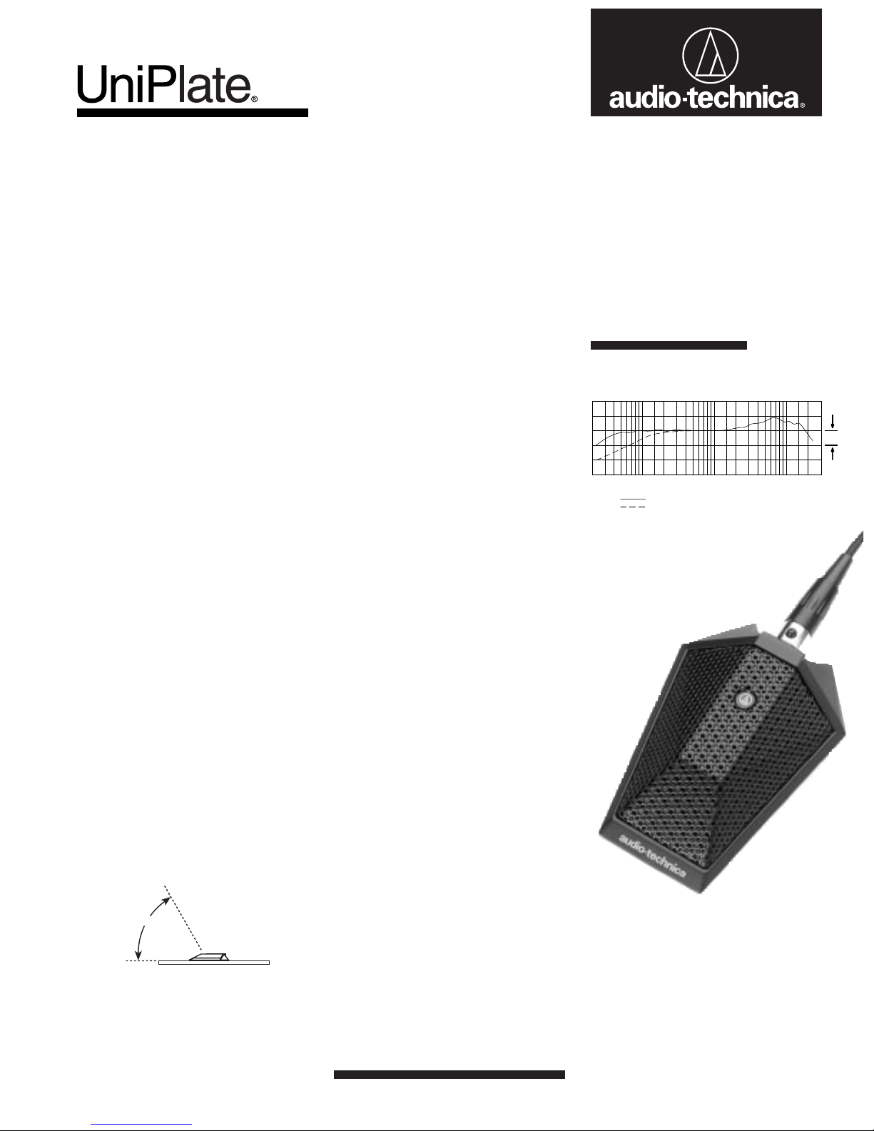
Frequency Response
60°
IDEAL
WORKING
ANGLE
Output is low impedance balanced. The output
connector of the power module mates with
XLRF-type cable connectors. The balanced
signal appears across Pins 2 and 3, while the
ground (shield) connection is Pin 1. Output is
phased so that positive acoustic pressure produces positive voltage at Pin 2 in accordance
with industry convention.
50
LEGEND
500
200100
Frequency in Hertz
12" or more on axis (flat)
Roll-off
1k
10 dB
Response in dB
2k
10k
5k
20k
AT851Rx
AT851RWx
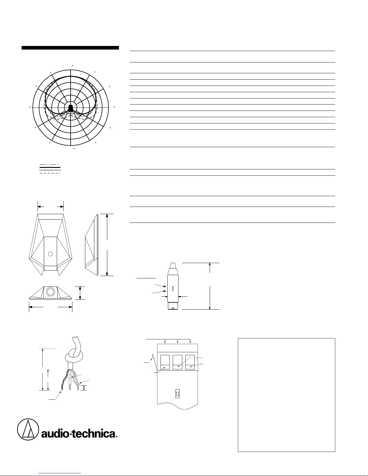
Polar Pattern
0
330
300
270
240
210
180
LEGEND
200 Hz
1 kHz
5 kHz
8 kHz
SCALE IS 5 DECIBELS PER DIVISION
Dimensions
1.54"
39.0 mm
2.52"
64.0 mm
Figure 1 Figure 2
1"
1
/2"
Shield strands,
fully twisted
Audio-Technica U.S., Inc.,1221 Commerce Drive, Stow, Ohio 44224
Audio-Technica Limited,Old Lane, Leeds LS11 8AG England
Form No. 0310-0858-00-B/W P50872 © 1995 Audio-Technica U.S., Inc. Printed in U.S.A.
30
150
0.63"
16.0 mm
Yellow-Yellow
Red-Red
1
/8" strip reds
and yellows
60
90
120
3.60"
91.5 mm
AT851Rx/AT851RWx SPECIFICATIONS
ELEMENT Fixed-charge back plate
POLAR PATTERN Half-cardioid (cardioid in hemisphere above
†
permanentlypolarized condenser
mounting surface)
FREQUENCY RESPONSE 30-20,000 Hz
LOW-FREQUENCY ROLL-OFF 150 Hz, 6 dB/octave
OPEN CIRCUIT SENSITIVITY –43 dB (7.0 mV) re 1V at 1 Pa*
IMPEDANCE 200 ohms
MAXIMUM INPUT SOUND LEVEL 138 dB SPL, 1 kHz at 1% T.H.D.
DYNAMIC RANGE (TYPICAL) 111 dB, 1 kHz at Max SPL
SIGNAL-TO-NOISE RATIO
1
67 dB, 1 kHz at 1 Pa*
SWITCH Flat response, low-roll-off (recessed)
PHANTOM POWERREQUIREMENTS 9-52V DC, 2 mA typical
WEIGHT (LESS CABLE AND ACCESSORIES)
MICROPHONE 4.2 oz (120 grams)
POWER MODULE 2.1 oz (60 grams)
DIMENSIONS
MICROPHONE 2.52" (64.0 mm) max width, 3.60" (91.5 mm)
max length, 0.63" (16.0 mm) height
POWER MODULE 3.58" (91.0 mm) long, 0.83" (21.0 mm) diameter
OUTPUT CONNECTOR (POWER MODULE) Integral 3-pin XLRM-type
CABLE 25' (7.6 m) long, 0.13" (3.2 mm) diameter,
ACCESSORIES FURNISHED AT8533x power module; battery;
OPTIONAL INTERCHANGEABLE ELEMENTS AT853H-ELE hypercardioid (100°)
AT8533x Power Module Dimensions
2-conductor, shielded cable with TA3F connector
at microphone end; pigtail output attaches to
screw terminals in power module
soft vinyl protective pouch
AT853O-ELE omnidirectional (360°)
AT853SC-ELE subcardioid (170°)
†
In the interest of standards development, A.T.U.S. offers
full details on its test methods to other industry
professionals on request.
*1Pascal = 10 dynes/cm
1
Typical, A-weighted, using Audio Precision System One.
2
= 10 microbars = 94 dB SPL
Optional Accessories:
•CP8201 line matching transformer
(Lo-Z to 50,000 ohms).
SWITCH
Roll-off
Flat
3.58"
91.0 mm
0.83"
21.0 mm
•AT8202 adjustable in-line attenuator for use
with low-impedance microphones.
•AT8314 2-conductor, shielded, vinyl-jacketed,
broadcast-type cable with XLRF-type connector
at microphone end,XLRM-type connector at
equipment end. Available in 10', 20', 25', 30',
50' & 100' lengths.
•CP8506 four-channel 48V phantom power
supply (AC powered).
•CP8508 single-channel 24V phantom power
supply (AC powered).
Terminal
screws
Case
grounding
contact
Shield
S Y R
PC board
switch side
Yellow-Yellow
Red-Red
One-Year Limited Warranty
Audio-Technica microphones and accessories purchased in the U.S.A. are warranted for one year from
date of purchase by Audio-Technica U.S., Inc. (A.T.U.S.)
to be free of defects in materials and workmanship. In
event of such defect, product will be repaired promptly
without charge or, at our option, replaced with a new
product of equal or superior value if delivered to
A.T.U.S. or an Authorized Service Center, prepaid,
together with the sales slip or other proof of purchase
date.
Prior approval from A.T.U.S. is required for
return.
This warranty excludes defects due to normal
wear, abuse, shipping damage, or failure to use product
in accordance with instructions. This warranty is void in
the event of unauthorized repair or modification.
For return approval and shipping information,
tact the Service Department, Audio-Technica U.S., Inc.,
1221 Commerce Drive, Stow, Ohio 44224.
Except to the extent precluded by applicable state law,
A.T.U.S. will have no liability for any consequential,
incidental, or special damages; any warranty of
merchantability or fitness for particular purpose
expires when this warranty expires.
This warranty gives you specific legal rights, and you
may have other rights which vary from state to state.
Outside the U.S.A., please contact your local dealer
for warranty details.
con-
 Loading...