

Page 1
U853PM & U853PMW
Cardioid Condenser Hanging Microphones
Features
• Wall/ceiling plate power module permits permanent installation
in standard, single-gang electrical box
• Uniform cardioid polar pattern with 120º acceptance angle
• Low-prole design with low-reectance nish for minimum
visibility
• Superior off-axis rejection for maximum gain before feedback
• UniGuard
of radio frequency interference (RFI)
• UniSteep
minimize pickup of undesired ambient noise
• Available interchangeable elements permit angle of acceptance
from 90º to 360º
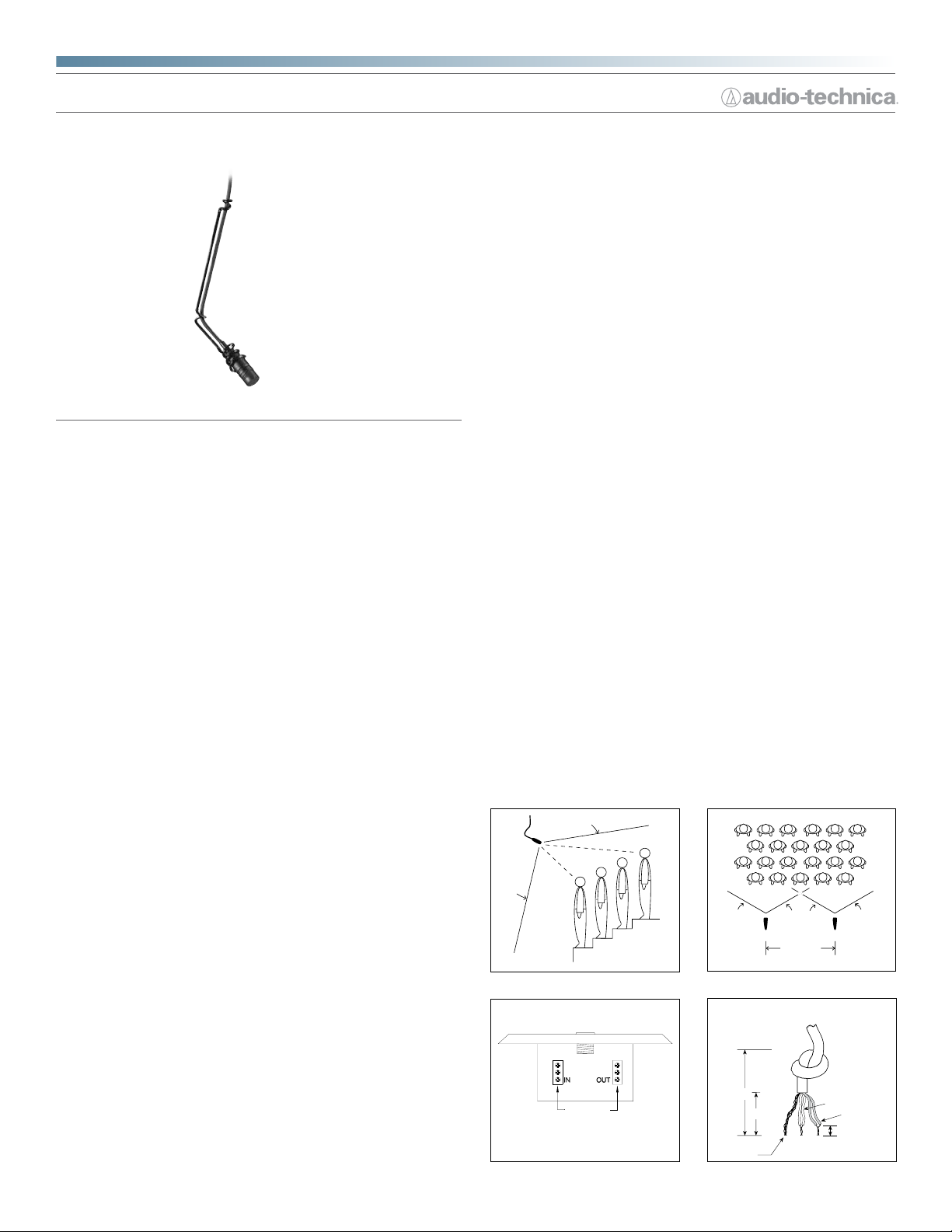
• Steel hanger positions microphone over choirs, instrumental
groups and theater stages
• Available in two colors: black (U853PM) and white (U853PMW)
Description
The U853PM is a wide-range miniature condenser microphone with a cardioid
polar pattern. It is designed for quality sound reinforcement, professional
recording, television and other demanding sound pickup applications. The
combination of small size and excellent response makes the microphone ideal
for suspension over choirs, instrumental groups or theater stages.
The microphone requires 11V to 52V phantom power for operation.
The microphone is equipped with UniGuard
offers outstanding rejection of radio frequency interference (RFI).
The microphone's cardioid polar pattern provides a 120° angle of acceptance.
Additional interchangeable elements with omnidirectional (360°), hypercardioid
(100°) and UniLine
®
RFI-shielding technology offers outstanding rejection
®
lter provides a steep low-frequency attenuation to
®
RFI-shielding technology, which
®
(90°) pickup patterns are available.
unipoint® microphones
Installation and Operation
The U853PM requires 11V to 52V phantom power for operation.
A uniform 120° angle of acceptance provides well-balanced audio pickup. The
microphone should be located forward of the front-most source, above the
rear-most source, and “aimed” between them (Fig.1). Increasing the height of
the mic above the sources will tend to equalize sound levels between them,
but may also increase background/reverberant sound pickup. When possible,
the distance from the mic to the rear-most source should be no more than
twice the distance to the front source, to maintain front-to-rear balance (Fig. 1).
Width of pickup is approximately three times the distance to the closest
performer. If additional mics are needed for wide sources, they should be
positioned apart laterally at least three times the distance to the front source,
to avoid phase cancellation (Fig. 2). To orient the microphone in the proper
direction, twist the housing slightly in its wire holder. (Clockwise rotation
moves the microphone to the right; counterclockwise rotation moves it to the
left.)
The provided two-stage foam windscreen simply slips over the head of the
microphone, effectively reducing noise from wind or ventilation air currents.
®
An integral 80 Hz high-pass UniSteep
lter provides easy switching from a
at frequency response to a low-end roll-off. The roll-off position reduces the
pickup of low-frequency ambient noise (such as trafc, air-handling systems,
etc.), room reverberation and mechanically coupled vibrations. To engage the
UniSteep
®
lter, slide the switch toward the “bent” line. A 10 dB gain switch
is provided for situations that demand extra sensitive pickup. The +10 position
increases the microphone's overall output by 10 dB. To engage the 10 dB gain,
slide the switch toward the +10 position.
The AT8534 wall/ceiling plate power module is designed to be mounted
in a standard metal U.S. single-gang electrical box. For safety and best
performance, use the electrical box only for the AT8534; do not include any AC
power conductors. (Also route the mic cable as far away from AC power cables
as possible.)
Screw-terminal output connections of the AT8534 are the same as those
of an XLR-type plug: shield to Terminal 1, balanced signal and phantom
power to Terminals 2 and 3. Output is phased so that positive acoustic
pressure produces positive voltage at Terminal 2, in accordance with industry
convention. Do not connect the output cable shield to the box. Double-
check to make certain that all input and output leads have no bare wires or
loose strands that could touch each other, the circuit board or the electrical box.
Then attach the power module plate to the electrical box.
LES
S T
H
AN 2
TIMES
“
X
D
IS
T
A
N
CE
“
X
”
”
The microphone includes a 7.6 m (25') permanently attached miniature cable.
Its free end connects to the provided AT8534 wall/ceiling plate power module
via a special TA3F-type connector designed to optimize RFI immunity. The
power module features a white-nished standard electrical cover plate for
easy, secure installation. Output connections on the power module are screw
terminals.
Switches in the power module permit a +10 dB gain setting for extra sensitive
pickup as well as a choice of at response or low-frequency roll-off (via integral
80 Hz high-pass UniSteep
®
lter) to help control undesired ambient noise.
The microphone comes equipped with a wall/ceiling plate power module,
a vinyl-coated steel hanger for positioning over a choir/orchestra/stage, a
two-stage foam windscreen, and a
5
/8"-27 stand adapter. The microphone is
enclosed in a rugged housing with a low-reectance black nish. It is also
available with white housing, cable, hanger and windscreen as the U853PMW.
120°
ANGLE OF
ACCEPTANCE
Figure 1 Figure 2
AUDIO -
RED/
YEL / YEL
SHIELD
INPUT
v+
RED
SIG
GND
Terminal screws
3
2
1
AUDIO +
SHIELD
OUTPUT
Shield strands,
fully twisted
Figure 3 Figure 4
MIC A MIC B
3 TIMES
DISTANCE “X”
1"
1
/2"
120°120°
Yellow-Yellow
Red-Red
1
/8" strip reds
and yellows
Page 2
343
U853PM & U853PMW
Connect the TA3F-type connector from the microphone's cable to the TA3Mtype connector in the power module plate.
Note: Audio-Technica has developed a special RFI-shielding mechanism that
is an integral part of the connectors in the UniPoint
®
line. If you remove or
incorrectly replace the connector, you may adversely affect the unit's RFI
immunity. Audio-Technica offers a crimp tool (ATCT) and RFI shields that enable
you to shorten the cable and correctly reinstall the connector while maintaining
the highest level of RFI immunity.
If you need to shorten the cable between the microphone and power module,
it can be done two ways:
a. To maintain original RFI shielding (see note above), the TA3F-type connector
can be removed from the cable end, the cable shortened and the connector
replaced using Audio-Technica's available crimp tool and RFI shield for TA3Ftype connector.
b. If RFI immunity is not required, the TA3M-type connector on the plate can
be removed and discarded (save the back nut and washer). Assemble the
included plastic ferrule into the hole left from the TA3M-type connector, using
the washer and nut from the connector to secure the ferrule. Cut the cable to
the desired length plus a few inches. Thread the cable through the ferrule and
tie a knot in the cable behind the ferrule to secure it. Carefully strip the ends
of the cable and connect the wires to the terminals formerly occupied by the
TA3M-type connector. Maintain color coding (Shield - S, Yellow - Y, Red - R) and
connect the microphone wires to the appropriate terminal screws (Fig. 3).
Note: The cable has two red wires and two yellow wires. Twist the two red
wires together and the two yellow wires together (Fig. 4).
Avoid leaving the microphone in the open sun or in areas where temperatures
exceed 110° F (43° C) for extended periods. Extremely high humidity should
also be avoided.
Architect’s and Engineer’s Specications
The microphone shall be a xed-charge condenser designed for permanent
installation. It shall have a cardioid polar pattern with a uniform 120° angle
of acceptance and a frequency response of 30 Hz to 20,000 Hz. It shall be
capable of accepting optional interchangeable elements for additional polar
patterns. The microphone shall operate from an external 11V to 52V DC
phantom power source. It shall be capable of handling sound input levels up to
128 dB with a dynamic range of 102 dB. Nominal open-circuit output voltage
shall be 11.2 mV at 1 V, 1 Pascal. Output shall be low impedance balanced (200
ohms). It shall offer outstanding rejection of radio frequency interference (RFI).
The microphone shall have a 7.6 m (25') permanently attached miniature cable
terminating in a special TA3F-type output connector designed to optimize RFI
immunity. The output connector shall connect to a TB3M-type jack on the
included power module. Output connections on the power module shall be
screw terminals. The plate power module shall be designed to mount over
a standard single-gang metal electrical box for ceiling or wall mounting. The
power module shall contain a switch to permit choice of at response or 80
Hz low-frequency roll-off. In addition, the power module shall incorporate a
switchable +10 dB gain setting. The power module face plate shall be semigloss white and mounting screws shall be included.
An adjustable steel wire hanger shall be provided for suspended installations.
The steel wire hanger shall attach to the microphone body and allow for the
positioning of the microphone without the need for tools. A two-stage foam
windscreen and a
5
/8"-27 stand adapter shall also be included.
The microphone shall be a hanging design, with overall length of 34.0 mm
(1.34") and a head diameter of 12.2 mm (0.48"). Weight shall be 14 grams
(0.5 oz) without cable. The microphone cable and steel hanger shall be
black [white].
The Audio-Technica U853PM [U853PMW] is specied.
Specications
Element
Polar pattern
Frequency response
Low frequency roll-off
Open circuit sensitivity
Impedance
Maximum input sound level
Dynamic range (typical)
Signal-to-noise ratio
Phantom power requirements
Switches
Weight
Dimensions
Output connector
Cable
Optional interchangeable elements
Audio-Technica case style
Accessories furnished
U853PM
U853PMW
In the intere st of standards develo pment, A.T.U.S. offers full
details on it s test methods to othe r industry
1 Pascal = 10 dynes/cm
1
Typical, A-weighted , using Audio Precisio n System One.
Specications are subject to change without notice.
professionals on request.
2
= 10 microba rs = 94 dB SPL
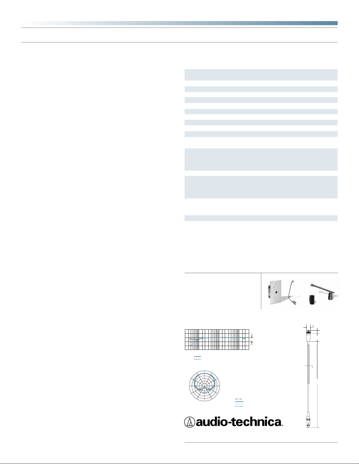
frequency response: 30–20,000 Hz
10 dB
100
12" or more on axis
Roll-off
330˚
200
Frequency in Hertz
0˚
180˚
500
30˚
150˚
5k
2k
1k
60˚
120˚
10k
20k
90˚
LEGEND
200 Hz
1 kHz
5 kHz
8 kHz
50
LEGEND
polar pattern
300˚
270˚
240˚
210˚
SCALE IS 5 DECIBELS PER DIVISION
Fixed-charge back plate, permanently
polarized condenser
Cardioid
30-20,000 Hz
80 Hz, 18 dB/octave
–39 dB (11.2 mV) re 1V at 1 Pa
200 ohms
128 dB SPL, 1 kHz at 1% T.H.D.
102 dB, 1 kHz at Max SPL
1
68 dB, 1 kHz at 1 Pa
11-52V DC, 4 mA typical
Flat, roll-off; 0 dB/+10 dB gain setting
Microphone: 14 g (0.5 oz)
Power module: 97 g (3.4 oz)
Microphone: 34.0 mm (1.34") long,
12.2 mm (0.48") diameter
Power module: 71.0 mm (2.80") W x
115.5 mm (4.55") H x 36.0 mm (1.42") D
Power module: Screw terminals
7.6 m (25.0') long (permanently attached
to microphone), 3.2 mm (0.13") diameter,
2-conductor, shielded cable with TA3Ftype connector
UE-O omnidirectional (360°)
UE-H hypercardioid (100°)
UE-UL UniLine® (90°)
M12
AT8534 wall/ceiling plate power module;
AT8451 steel hanger; AT8153 two-stage
foam windscreen; AT8438 5/8"-27 stand
adapter
AT8534 wall/ceiling plate power module;
AT8451(WH) steel hanger; AT8153(WH)
two-stage foam windscreen; AT8438 5/8"-27
stand adapter
0.48"
12.2 mm
0.39"
10.0 mm
0.95"
24.0 mm
Response in dB
0.13"
3.2 mm
25'
7.6 m
Audio-Technica U.S., Inc., 1221 Commerce Drive, Stow, Ohio 44224
Audio-Technica Limited, Old Lane, Leeds LS11 8AG England
©2010 Audio-Technica U.S., Inc. audio-technica.com 0001-0157-01
 Loading...