

Page 1

3000 Series
Frequency-agile True Diversity UHF Wireless System
-TUNER-
ON
OFF
POWER
ALERT
UHF SYNTHESIZED DIVERSITY RECEIVER ATW-R3100b
A
B
MODE/SET
Installation and Operation
3000 Series
Frequency-agile True Diversity UHF Wireless System
French
French
French
Spanish
Spanish
Spanish
Portuguese
Portuguese
Portuguese
German
German
German
Italian
Italian
Italian
Dutch
Dutch
Dutch
Traditional Chinese
Traditional Chinese
Traditional Chinese
Simplified Chinese
Simplified Chinese
Simplified Chinese
Korean
Korean
Korean
Page 2

2
3000 Series Installation and Operation
(english)
This device complies with part 15 of the FCC Rules. Operation is
subject to the condition that this device does not cause harmful
interference.
This device complies with INDUSTRY CANADA R.S.S. 210, en
conformité avec IC: RSS-210/CNR210. Operation is subject to the
following conditions: 1) This device may not cause harmful interference
and 2) this device must accept any interference received, including
interference which may cause undesired operation.
CAUTION! Electrical shock can result from removal of the receiver
cover. Refer servicing to qualied service personnel. No userserviceable parts inside.
• Do not expose batteries to excessive heat such as re, near heating
units or in direct sunlight.
• To prevent re or shock hazard, do not expose this product to rain
or moisture.
• To prevent re, do not place any naked ame sources (such as
lighted candles) on the apparatus.
• To prevent re, do not cover the ventilation of the apparatus with
newspaper, tablecloths, curtains etc.
• Do not expose this apparatus to drips or splashes.
• Do not place any objects lled with liquids, such as vases, on the
apparatus.
• Do not install this apparatus in a conned space such as a bookcase
or similar unit.
• The apparatus should be located close enough to the AC outlet
so that you can easily grasp the AC adapter at any time. In case of
emergency, disconnect the AC adapter quickly.
• Always consider environmental issues and follow your local
regulations when disposing of batteries. Do not expose batteries to
excessive heat.
The circuits inside the receiver and transmitter have been precisely
adjusted for optimum performance and compliance with federal
regulations. Do not attempt to open the receiver or transmitter. To do so
will void the warranty, and may cause improper operation.
Notice to individuals with implanted cardiac pacemakers
or AICD devices:
Any source of RF (radio frequency) energy may interfere with normal
functioning of the implanted device. All wireless microphones have
low-power transmitters (less than 0.05 watts output) which are unlikely
to cause difculty, especially if they are at least a few inches away.
However, since a “body-pack” mic transmitter typically is placed against
the body, we suggest attaching it at the belt, rather than in a shirt
pocket where it may be immediately adjacent to the medical device.
Note also that any medical-device disruption will cease when the RF
transmitting source is turned off. Please contact your physician or
medical-device provider if you have any questions, or experience any
problems with the use of this or any other RF equipment.
RF Interference
Please note that wireless frequencies are shared with other radio
services. According to Federal Communications Commission
regulations, “Wireless microphone operations are unprotected
from interference from other licensed operations in the band. If any
interference is received by any Government or non Government
operation, the wireless microphone must cease operation...” If you
need assistance with operation or frequency selection, please contact
your dealer or Audio-Technica.
Thank you for choosing this Audio-Technica 3000 Series Frequency-agile
True Diversity UHF Wireless System.
The 3000 Series wireless system is available in six UHF frequency
bands to provide exible performance in a wide variety of regions
worldwide:
Frequency Range Number of frequencies
Band C 541.500 – 566.375 MHz 996
Band D 655.500 – 680.375 MHz 996
Band E 795.500 – 820.000 MHz 981
Band F 840.125 – 864.900 MHz 953
Band G 721.500 – 746.375 MHz 996
Band I 482.000 – 507.000 MHz 1001
The band letter reference at the end of 3000 Series Stock Numbers
indicates what band the system/component operates in. For simplicity,
model numbers used throughout this manual will reference only the
basic model number without the band indications.
Each wireless system includes a receiver and either a body-pack or
handheld transmitter. UniPak® body-pack transmitter systems may
include an accessory microphone for a particular application. All A-T
Wireless Essentials® microphones and cables, available separately, are
pre-terminated for use with any Audio-Technica 3000 Series wireless
system.
All 3000 Series components feature soft-touch controls for quick, easy
access to a formidable range of functions; an LCD information display
in each unit provides convenient visual indication of unit settings and
operation.
The ATW-R3100b receiver is equipped with automatic frequency
scanning for easy setup. It also features true diversity reception. Two
antennas feed two completely independent RF sections on the same
frequency; automatic logic circuitry continuously compares and selects
the superior received signal, providing better sound quality and reducing
the possibility of interference and dropouts. Soft-touch controls
provide convenient access to a variety of functions, while a backlit LCD
information display provides constant monitoring of system operation,
including indication of the transmitter’s battery status. The receiver is
half-width for a standard 1U 19" rack mount; rack-mount adapters are
included. Two receivers can be mounted side by side, using an optional
AT8630 joining-plate kit.
The versatile ATW-T310b UniPak® body-pack transmitter has both
low- and high-impedance inputs plus a bias connection, for use
with dynamic and electret condenser microphones, as well as Hi-Z
instrument pickups. In addition to its programmable functions, the
transmitter features a three-position sliding cover to limit access, if
desired, to just the Power/Mute button, or to cover all the controls,
as appropriate for the application and user. The ATW-T341b handheld
dynamic microphone/transmitter features the same element used in
the Artist Elite® AE4100 dynamic handheld microphone created for
professional livesound venues. The ATW-T371b handheld condenser
microphone/transmitter features the same element used in the Artist
Series ATM710 cardioid condenser vocal microphone.
Transmitters in the 3000 Series use two 1.5V AA batteries for
economical operation and wide availability. The receiver and both
transmitters have “fuel gauge” battery condition indicators with lowbattery warnings.
An advanced Digital Tone Lock™ tone squelch system in the
ATW-R3100b receiver opens only when a 3000 Series transmitter
Page 3

3
is detected, reducing the possibility of interference. As a result, 3000
Series transmitters and receivers must be used together and should
not be used with components from other Audio-Technica wireless
systems, or with those of other manufacturers. Exception: 3000 Series
components are compatible with Audio-Technica 1800 Series wireless
system components.
Please note that in multiple-system applications there must be a
transmitter-receiver combination set to a separate frequency for each
input desired (only one transmitter for each receiver). Because the
wireless frequencies are within UHF TV frequency bands, only certain
operating frequencies may be useable in a particular geographic area.
Receiver Installation
Location
For best operation the receiver should be at least 3 ft. (1 m) above the
ground and at least 3 ft. away from a wall or metal surface to minimize
reections. The transmitter should be at least 3 ft. from the receiver,
as shown in Figure A. Keep antennas away from noise sources such
as digital equipment, motors, automobiles and neon lights, as well as
away from large metal objects.
Fig. A
Output Connections
There are two audio outputs on the back panel: balanced and
unbalanced. Use shielded audio cable for the connection between the
receiver and the mixer. If the input of the mixer is a 1/4" jack, connect a
cable from the 1/4" unbalanced audio output on the back of the receiver
housing to the mixer. If the input of the mixer is an XLR-type input,
connect a cable from the balanced XLR-type audio output on the back
panel to the mixer. The two isolated audio outputs permit simultaneous
feeds to both unbalanced and balanced inputs. For example, both a
guitar amp and a mixer can be driven by the receiver.
Antennas
Attach the included pair of UHF antennas to the antenna input jacks.
The antennas are normally positioned in the shape of a “V” (both 45°
from vertical) for best reception.
Antennas can be remotely located from the receiver. However, due
to signal loss in cables at UHF frequencies, use the lowest-loss RF
cables practical for any cable runs over 8 m/25 feet. RG8-type is a good
choice. Use only copper-shielded cable, not CATV-type foil-shielded
wire. Audio-Technica offers quality RF cables in four lengths, as well as
remote antennas.
Either passive or active antennas may be used. Both input jacks
offer switchable +12 V DC output on their center pins to operate
Audio-Technica powered antennas or other in-line RF devices if desired.
Up to 60 mA can be drawn from each antenna input jack.
Power Connections
Connect the included AC adapter to the DC power input on the back of
the receiver. Loop the small cord from the DC plug over the cord hook
above the jack, to keep the plug from being detached by an accidental
tug on the cord. Then plug the AC adapter into an AC power outlet.
Operation of the receiver is controlled by the front-panel Power switch.
3000 Series Installation and Operation
(english)
Receiver Controls and Functions
Front Panel Controls and Functions
Fig. B
1. POWER SWITCH: Press Power switch in and the receiver
readouts will light.
2. ALERT INDICATOR: The Alert Indicator lights:
(a) When the receiver is in the Function Edit mode,
(b) When no RF signal is received from transmitter,
(c) When only one or two RF signal-strength bars are on,
(d) When the transmitter is in the Mute mode,
(e) When audio modulation level from the transmitter is close to the
clipping point (AF +3/+6 bars),
(f) When only one bar of the Battery “fuel gauge” is on (transmitter
battery is weak).
3. LCD WINDOW: Backlit screen indicates control settings and
operational readings. See Figure D for examples.
4. TUNER OPERATION INDICATOR: Indicates which Tuner (A or B) has
the better reception and is in operation. The “B” indicator also lights
to serve as conrmation of Mode/Set button entries.
5. UP/DOWN BUTTONS: Press Up or Down arrow buttons, in
conjunction with the Mode/Set button, to step through menus,
select operating frequency and edit receiver function choices.
6. MODE/SET BUTTON: Use in conjunction with the Up/Down arrow
buttons to step through menus, choose operating frequency, initiate
automatic scanning and select receiver function options.
7. MOUNTING ADAPTERS: For mounting the receiver in any standard
19" rack. Attach adapters to the receiver with the screws supplied
and remove the four receiver feet. (Use optional AT8630 joining plate kit to mount two ATW-R3100b receivers side-by-side.)
Rear Panel Controls and Functions
Fig. C
8. ANTENNA INPUT JACK: BNC-type antenna connector for Tuner “B.”
Attach the antenna directly, or extend it with a low-loss antenna
cable.
9. ANTENNA INPUT JACK: Input for Tuner “A.” Attach the antenna
directly, or extend it with a low-loss antenna cable.
10. AF LEVEL CONTROL: Adjusts audio output level of both AF Output
jacks; maximum output is fully clockwise.
11. GROUND LIFT SWITCH: Disconnects the ground pin of the
balanced output jack (12) from ground. Normally, the switch should
1 2 3 4 5 6
ON
POWER
OFF
ALERT
ON
POWER
OFF
UHF SYNTHESIZED DIVERSITY RECEIVER ATW-R3100b
8 9 10
ANT. B
ALERT
UHF SYNTHESIZED DIVERSITY RECEIVER ATW-R3100b
7
-TUNER-
A
MODE/SET
B
AF
LEVEL
ANT. A
GROUND
GROUND LIFT
11 13 14
-TUNER-
A
B
AF OUT
BALANCED
MODE/SET
AF OUT
UNBALANCED
1512
DC500 mA
12~18V
Page 4

4
3000 Series Installation and Operation
(english)
be to the left (ground connected). If hum caused by a ground loop
occurs, slide switch to the right (ground lifted).
12. BALANCED AUDIO OUTPUT JACK: XLRM-type connector. A
standard 2-conductor shielded cable can be used to connect the
receiver output to a balanced microphone-level input on a mixer or
integrated amplier.
13. UNBALANCED AUDIO OUTPUT JACK:
1
/4" phone jack. Can be
connected to an unbalanced aux-level input of a mixer, guitar amp
or tape recorder.
14. POWER INPUT JACK: Connect the DC plug from the included in-line
AC adapter.
15. CORD HOOK: Loop the small DC cord around the cord hook to keep
the DC plug from pulling out accidentally.
Power On/Off
To turn the receiver on, press in the Power switch. The Alert light and
the LCD window will come on (about 1-2 seconds). The operating
frequency will be displayed in the window after the power-up sequence.
To turn the receiver off, press the Power switch again.
LCD Window
The LCD (Liquid Crystal Display) presents a great deal of setup and
operating information clearly and conveniently. (See Figure D for
examples.)
Fig. D
8
7
6
5
4
3
2
1
BATTRF AF
D1. Normal Receiver Operation
(Transmitter off)
MHz
+6
+3
0
-3
-6
-9
-16
-20
D2. Menu Mode (Frequency) D3. Edit Mode (Frequency)
MHz MHz
ashing
Up/Down Arrow Buttons
In conjunction with the Mode/Set button, the arrow buttons permit
moving through the menu of functions, and they offer a choice of
settings within each function.
Mode/Set Button
The Mode/Set button shifts the receiver from normal operation into
Menu mode and, in conjunction with the Up/Down arrow buttons,
permits selection of different features and changing of their stored
values in the Edit mode.
How to Make Setting Changes
1. From the normal operating mode, press the Mode/Set button once
to enter the Function Menu mode. (Only the frequency will remain
in the LCD window, and the receiver’s audio output will be cut off.)
2. Use the Up/Down arrow buttons to reach the desired function.
The value in the LCD window is the current setting for that function.
3. Press the Mode/Set button once again to open the list of available
choices for that function. The value will ash, indicating that it can
be changed (Edit mode).
4. Use the arrow buttons to go through the available choices, stopping
on the desired new choice.
5. (a) To accept and enter the new choice, press and hold the Mode/
Set button until “STORED” appears in the LCD. This changes the
value and puts the function of the buttons back at Menu level (step
2 above). (The “B” tuner light will come on while the Mode/Set
button is depressed, to conrm its action.)
(b) To “back out” of the Edit mode without making a new choice,
simply press the Mode/Set button once. The word “ESCAPE” will
appear in the window and the function of the buttons will revert to
the Menu level (step 2 above), without making any changes.
6. Repeat this selection process for any other function changes
desired. When nished with any changes, use the arrow buttons to
move to “QUIT”. Press the Mode/Set button once to exit the
menu and return the receiver to normal operation. (“RF” and “AF”
will reappear in the window, indicating the return to normal receiver
operation, with the receiver’s audio output again enabled.)
Frequency Group Selection
To select a frequency scan group, press the Mode/Set button, then use
the arrow button until the desired group appears in the display. To store
the selected frequency scan group, press the Mode/Set button to enter
the desired group; then use the arrow button to start the scan. When a
ashing number is displayed, press and hold Mode/Set button to select
the frequency. See detailed instructions in System Operation.
How to Restore Default Settings
To return all the receiver functions to their original factory default
settings, rst turn the receiver off. Then hold in the Mode/Set button
while pressing and releasing the Power switch. The LCD will briey
show “RESET”, followed by “WAIT” (release the Mode/Set button),
before commencing normal-mode operation at the default settings.
When the receiver is in the Menu or Edit mode, its audio output is
silenced. Once control-setting operations are completed (or Escape
is used), normal receiver operation will resume with its audio output
restored.
While in the Edit mode, if no action is taken for approximately 30
seconds (no buttons pressed), the receiver will “back out” to the Menu
mode. Similarly, after about 30 seconds of inaction in the Menu mode,
the receiver will “back out” to normal receiver operation with audio
output restored.
High-pass Filter
Internal high-pass lter circuitry may be set to four positions: Highpass Off, or a 6 dB, 12 dB or 18 dB slope at 150 Hz. The default
setting is Off (“HP OFF”). Increasing the slope of the high-pass lter
further suppresses unwanted low frequencies, while maintaining the
frequency response in the desired audio range.
Meter Hold Setting
When activated (“MH ON”), this function permits the bar-meters in
the LCD window to capture and display the highest-level “AF” audio
modulation (a solid bar) and the lowest-level “RF” signal (a ashing bar)
received from the transmitter. This is particularly useful when setting
up the system initially, during a sound-check, or when diagnosing
operating problems. The default setting is Off (“MH OFF”).
When the Meter Hold is On, it is possible to reset it – to obtain a new
set of RF and AF readings – without turning it off-and-on using the
Menu/Edit functions. Simply press the transmitter’s Power/Mute button
once (to mute the transmitter) and wait until the receiver’s Alert light
comes on, indicating the Mute condition. Then press the transmitter’s
Power/Mute button once again, to un-mute the transmitter. After the
Alert light goes out, a new set of min/max RF/AF readings will be
indicated on the bar-meters. (Note that, depending upon the digital
updating-and-conrming sequence of the Mute condition data from
the transmitter, it may take several seconds for the Alert light condition
to change. The Meter Hold function is not reset until the Alert light
has turned on, then turned off.)
Digital Tone Lock™ Squelch
The 3000 Series employs a unique Digital Tone Lock squelch system
that provides enhanced rejection of interference. In addition to providing
highly effective control of unwanted noise, the Tone Lock signal from
the transmitter also conveys data on the transmitter’s battery condition
and mute status back to the receiver for display.
Page 5

5
The squelch level is adjustable from 15 dB (the default value) to 39 dB
in 6 dB steps. Increasing the squelch level – also called “tightening
the squelch” – can cause a reduction in useable range of the wireless
transmitter, so use the lowest value that reliably mutes the unwanted
RF signals. (If interference is a problem, rst consider trying a different
frequency.)
Antenna Power
The antenna input jacks also can provide +12V DC output on their
center pins to power inline RF devices. A maximum of 60 mA can be
drawn from each of the jacks. While an accidental short-circuit will not
harm the internal 12V supply, make certain that an antenna cable shield
does not contact the center conductor. Antenna Power (“ANT.PWR”) is
selected (switched on or off) from the LCD menu.
Pre-coordinated Frequency Scan Groups 1-9
The nine scan groups provided on the 3000 Series receivers simplify
the selection of usable frequencies in a multi-channel wireless system.
If you are using multiple systems, stay within one of the nine frequency
groups for all of your systems. The available frequencies within each
group have been selected for simultaneous use, eliminating the
frustration encountered when trying to select compatible frequecies in
a multi-channel system.
Scan Groups 8 and 9 have been designed to allow for use on adjoining
stages. Use Group 8 on one stage and Group 9 on a second nearby
stage. Or use these two groups in two different rooms, with one room
using Group 8, and the second using Group 9.
Receiver Functions
Function
Menu
▲▼
Group 6 Lowest in
Default
Setting*
frequency
3000 Series Installation and Operation
(continued)
Choices
▲▼
(Edit)
All frequencies
in Group 6
Wraparound**
No
(english)
group
▲▼
Group 7 Lowest in
frequency
All frequencies
in Group 7
No
group
▲▼
Group 8 Lowest in
frequency
All frequencies
in Group 8
No
group
▲▼
Group 9 Lowest in
frequency
All frequencies
in Group 9
No
group
▲▼
Quit
(exit Menu)
QUIT Press Mode/
Set to exit
–
* To reset to Default values, hold in the Mode/Set button while
pressing the Power button to turn on the unit.
** Continue in the same Up/Down direction and choices “wrap around”
to the other end of the range.
† Band I: 482.000 – 507.000 MHz; Band C: 541.500 – 566.375 MHz;
Band D: 655.500 – 680.375 MHz; Band G: 721.500 – 746.375 MHz;
Band E: 795.500 – 820.000 MHz; Band F: 840.125 – 864.900 MHz
Receiver Functions
Function
Menu
Default
Setting*
Choices
(Edit)
(Receiver powers-up at Frequency)
▲▼
Frequency Lowest in
band†
▲▼
High-pass
HP OFF HP OFF, HP–6,
Filter
▲▼
Meter Hold MH OFF MH OFF
All frequencies
in band
HP–12, HP–18
MH ON
▲▼
Squelch SQ 15 dB SQ 15 dB to
SQ 39 dB in
6 dB steps
▲▼
Antenna
Power
▲▼
Group 1 Lowest in
OFF PWR OFF
PWR ON
All frequencies
frequency
in Group 1
group
▲▼
Group 2 Lowest in
frequency
All frequencies
in Group 2
group
▲▼
Group 3 Lowest in
frequency
All frequencies
in Group 3
group
▲▼
Group 4 Lowest in
frequency
All frequencies
in Group 4
group
▲▼
Group 5 Lowest in
frequency
All frequencies
in Group 5
group
▲▼
Wraparound**
Yes
No
Yes
No
Yes
No
No
No
No
No
Transmitter Controls And Functions
Refer to Figures E, F, G and H for an overview of transmitter features
and controls.
LCD Window
The backlit Liquid Crystal Display presents a great deal of setup and
operating information clearly and conveniently (See examples in Fig. J).
The LCD in the transmitters is designed for greatest contrast and best
viewing with the window rotated somewhat away from the viewer
(about 30 degrees), not straight-on, for a more convenient holding/
viewing position. The display is illuminated with a backlight when you
power on the device and when you press Set to access transmitter
functions. The backlight remains on during the Set process, only
turning off if no action is taken within 30 seconds or if Quit is pressed;
otherwise, it automatically turns off in ten seconds.
Power/Mute Button
The transmitters have a combination Power and Mute switch. When
used in combination with the programmed choices explained below,
the various functions available to the transmitter user may be tailored to
t personal preferences or particular situations of use.
Power On/Off
To turn the transmitter on, press and hold the Power/Mute button until
the green power indicator and the LCD window come on (about 1-2
seconds). The operating frequency will show in the window after the
power-up sequence.
To turn the transmitter off, press and hold the Power/Mute button again,
until the green power indicator and the LCD window are extinguished
(about 1-2 seconds). The LCD window will show “PWR.OFF” before
shutdown.
Mute Off/On
When the transmitter is muted, it produces RF with no audio signal
Page 6

6
3000 Series Installation and Operation
(english)
modulation. When the transmitter is un-muted, it produces both RF and
audio.
To mute the transmitter (cut off the audio, but continue the RF output),
press and release the Power/Mute button once. A small “MUTE” will
appear in the LCD window, just below the frequency (Fig. M-2) and the
power/mute LED will change from green to red.
To un-mute the transmitter (restore the audio), press and release the
Power/Mute button once again. The “MUTE” will disappear from the
LCD window and the power/mute LED will change from red to green.
Fig. E
Sliding
Control Cover
(3-position)
ATW-T310b UHF TRANSMITTER
Door
Up/Down
Arrows
Power/Mute
Button
Mounting ClipSet ButtonBattery
Backlit
LCD Window
Antenna
Power-on LED
Audio Input Jack
Band C: Blue
Band D: Green
Band E: Black
Band F: Gray
Band G: Red
Band I: Orange
Power/Mute Locks
Programmable Power/Mute Locks limit the functioning of the Power/
Mute button as desired for particular users and/or applications. Power
can be locked On; Mute can be locked Off. Selection of the desired
locks, if any, is made through the function menu:
Setting Description
NO.LOC The normal Power and Mute functions are fully
operational.
ALL.LOC Both the Power and Mute functions are locked
into their status as of the time “ALL.LOC” is
applied. (Power On, and Mute either On or Off.)
Note: ALL.LOC must be re-accessed and the
setting changed to turn the transmitter off.
MUT.LOC In this mode, the audio cannot be muted.
The Power functioning is unaffected. (If MUT.LOC is
applied while the transmitter is muted, pressing
the Power/Mute button once will return to
un-muted operation; thereafter the Mute function
is disabled until the setting is changed again.)
PWR.LOC Power is locked On as of the time “PWR.LOC”
is applied. The Mute functioning is unaffected.
Note: When in the PWR.LOC mode, the
transmitter may be turned off by: (1) Re-accessing
the .LOC Menu and changing the setting, or
(2) Removing and re-installing the batteries. When
the transmitter is turned on again, it will power-up
in the NO.LOC mode. (Only the PWR. LOC
function will change when batteries are removed;
all other settings remain stored in memory.)
If an attempt is made to take an action that currently is locked
out, the LCD will display “LOCKED” briey, then return to its
previously-displayed contents.
Fig. F
Button
Fig. G
Fig. H
Antenna Housing
Backlit
LCD Window
Power-on LEDPower/Mute
Backlit
LCD Window
Power-on LED Set Button
Up/Down
Arrows
SET
Audio Input Selector
The UniPak
®
body-pack transmitter provides input connections for
both low-impedance (Lo-Z) microphones and high-impedance (Hi-Z)
instruments. A wide range of Audio-Technica Wireless Essentials®
microphones and cables is available pre-terminated with the appropriate
professional latching connector. Selection of the desired input –
microphone or instrument – is made through the function menu.
Depending upon the input selected, a small “MIC” or “INST” will
show in the LCD window, just below the frequency. (In the handheld
transmitter, only “MIC” will show in the LCD window.)
Frequency Group Selection
To select a frequency scan group, press the Set button, then use the up
or down arrow until the desired group appears in the display. To store
the selected frequency scan group, press the Set button to enter the
desired group; then use the arrow button to nd desired frequency.
Press and hold Set button to select the frequency. See detailed
instructions in System Operation.
Restore Default Settings
A “PRESET” selection in the menu permits resetting of all transmitter
functions to their factory-default values.
1. Press the Set button once to move to Menu mode.
2. Press the Up arrow twice to move to “PRESET” in the LCD window.
3. Press the Set button once and “LOAD” will appear in the LCD.
4. Press and hold the Set button until “DEF” appears in the LCD.
5. Press and hold the Set button until “LOADED” appears briey in the
LCD. The window will then revert to “PRESET”.
6. Press the Down arrow once to move to “QUIT”.
7. Press the Set button once to exit the Menu mode and return to
normal operation, with all factory-default settings restored.
Page 7

7
UniPak® Transmitter Functions
Function
Menu
Default
Setting*
Choices
▲▼
(Edit)
(Transmitter powers-up at Frequency)
▲▼
Frequency Lowest in
band†
▲▼
RF Power RF LOW RF LOW, RF HI Yes
▲▼
Audio Input
+6 dB –6 dB, 0 dB,
Level
▲▼
Power/Mute
NO.LOC
Locks
▲▼
Input Select MIC MIC, INST Yes
▲▼
Group 1 Lowest in
frequency
All frequencies
in band
+6 dB, +12 dB
NO.LOC, ALL.LOC,
MUT.LOC,
PWR.LOC
All frequencies
in Group 1
group
▲▼
Group 2 Lowest in
frequency
All frequencies
in Group 2
group
▲▼
Group 3 Lowest in
frequency
All frequencies
in Group 3
group
▲▼
Group 4 Lowest in
frequency
All frequencies
in Group 4
group
▲▼
Group 5 Lowest in
frequency
All frequencies
in Group 5
group
▲▼
Group 6 Lowest in
frequency
All frequencies
in Group 6
group
▲▼
Group 7 Lowest in
frequency
All frequencies
in Group 7
group
▲▼
Group 8 Lowest in
frequency
All frequencies
in Group 8
group
▲▼
Group 9 Lowest in
frequency
All frequencies
in Group 9
group
▲▼
Reset to
Defaults
PRESET LOAD (b) hold
until: DEF (c)
hold until:
LOADED
▲▼
Quit
(exit Menu)
QUIT Press Set to
exit
Wrap-around
Yes
No
Yes
Yes
Yes
Yes
Yes
Yes
Yes
Yes
Yes
Yes
–
–
3000 Series Installation and Operation
Handheld Transmitter Functions
Function
Menu
(Transmitter powers-up at Frequency)
▲▼
Frequency Lowest in
▲▼
RF Power RF LOW RF LOW, RF HI Yes
▲▼
Audio Input
Level
Dynamic
Condenser**
▲▼
Power/
Mute Locks
▲▼
Group 1 Lowest in
▲▼
Group 2 Lowest in
▲▼
Group 3 Lowest in
▲▼
Group 4 Lowest in
▲▼
Group 5 Lowest in
▲▼
Group 6 Lowest in
▲▼
Group 7 Lowest in
▲▼
Group 8 Lowest in
▲▼
Group 9 Lowest in
▲▼
Reset to
Defaults
▲▼
Quit
(exit Menu)
Default
Setting*
Choices
▲▼
(Edit)
All frequencies
band†
+6 dB
in band
-6 dB, 0 dB,
+6 dB, +12 dB,
+6 dB
0 dB, +6 dB,
+12 dB
NO.LOC
NO.LOC, ALL.LOC,
MUT.LOC,
PWR.LOC
All frequencies
frequency
in Group 1
group
All frequencies
frequency
in Group 2
group
All frequencies
frequency
in Group 3
group
All frequencies
frequency
in Group 4
group
All frequencies
frequency
in Group 5
group
All frequencies
frequency
in Group 6
group
All frequencies
frequency
in Group 7
group
All frequencies
frequency
in Group 8
group
All frequencies
frequency
in Group 9
group
PRESET LOAD (b) hold
until: DEF (c)
hold until:
LOADED
QUIT Press Set to
exit
(english)
Wraparound**
Yes
No
No
Yes
Yes
Yes
Yes
Yes
Yes
Yes
Yes
Yes
Yes
--
–
* Continue in the same Up/Down direction and choices “wrap around”
to the other end of the range.
** Additional 6 dB pad switch on capsule.
† Band I: 482.000 – 507.000 MHz; Band C: 541.500 – 566.375 MHz;
Band D: 655.500 – 680.375 MHz; Band G: 721.500 – 746.375 MHz;
Band E: 795.500 – 820.000 MHz; Band F: 840.125 – 864.900 MHz
Page 8
8
3000 Series Installation and Operation
(english)
Transmitter Setup
Battery Selection and Installation
Each transmitter uses two 1.5V AA batteries, not included. Alkaline
type is recommended; other types of 1.5V AA batteries (including
rechargeable) may be used, however performance may vary. Always
replace both batteries. Make certain the transmitter power is Off before
replacing batteries.
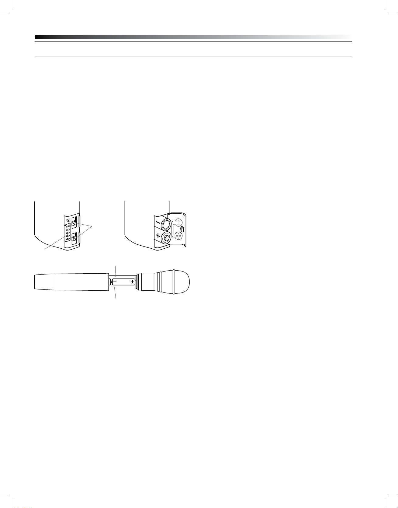
UniPak® Transmitter Battery Installation
1. Open the battery compartment door as follows:
Slide door lock down to the unlocked position. Pinch the release
arrows together to open the compartment. (Fig. J)
2. Observe correct polarity as marked on the metal contacts on the
door and carefully insert two fresh 1.5V AA alkaline batteries (Fig. K).
3. Close the door, making certain the latch clicks securely in place.
4. Slide the door lock up to the locked position.
Fig. J Fig. K
Release
Arrows
Door Lock
Fig. L
Serial Number
Start from this end
to remove batteries
The transmitter’s “fuel gauge” battery indicator displays a maximum of
four bar segments. When it ashes “LOW.BAT”, the batteries should
be replaced immediately to ensure continued operation. (The receiver
also displays transmitter battery condition in the LCD window with
bar segments; the Alert indicator comes on to warn of a low-battery
condition.)
UniPak® Transmitter Input Connection
Connect an audio input device (microphone or guitar cable) to the audio
input jack on the transmitter. A number of Audio-Technica professional
microphones and cables are available separately, pre-terminated with
a UniPak input connector. The cable connector latches automatically
when inserted into the transmitter jack. To unlatch and remove the
connector, simply pull up on the connector’s knurled metal collar.
UniPak® Transmitter Antenna
The UniPak transmitter includes a eld-replaceable exible antenna.
For best results, allow the antenna to extend to its full length from the
transmitter. If the received signal is marginal, experiment with different
transmitter positions on your body or instrument; or try repositioning
the receiver or using remote receiver antennas. Since the transmitter
antenna simply screws in, check it occasionally to make certain it
is snugly attached (nger-tight). Do not change the length of the
transmitting antenna.
Handheld Transmitter Antenna
The antenna for the handheld mic/transmitter is in the black,
non-metallic section at the bottom of the unit (Fig. F). For best results,
hold the mic/transmitter naturally, around its painted metal case;
holding or otherwise covering the antenna housing may reduce the
operating range.
UniPak® Transmitter Mounting Clip
The UniPak transmitter’s mounting clip may be installed with the case
positioned either “up” or “down,” depending upon which is preferred
for the application. To turn the clip around, pull the ends of the clip
out of the two holes on the sides of the transmitter case (Fig. E) and
reinstall it facing in the opposite direction.
Handheld Transmitter Battery Installation
1. While holding the lower body cover (near the LCD window), grasp
the upper part of the transmitter body just below the grille and
unscrew it at least four complete turns (Fig. G); then slide the
lower body cover down until it stops (Fig. H). Once the cover
has been lowered, turn the transmitter over to reveal the battery
compartment on the side opposite the LCD window.
2. Observe correct polarity as marked inside the battery compartment
and carefully insert two fresh 1.5V AA batteries (Fig. L). Insert the
rst battery and slide it down. Then insert the second battery,
bottom rst, into the space remaining. Make certain the batteries
are fully seated in the battery compartment.
3. Slide the lower body cover back up the body, then screw the
housing together. Do not overtighten.
Note: Remove batteries from the handheld transmitter starting at
the bottom (– end) of the top battery (Fig. L). The top (+ end) of the
top battery is captured in a recess and will not come straight out.
Battery Condition Indicator
After the batteries are installed, turn the power on by pressing and
holding the Power/Mute button. The small power-on LED (Fig. E/F)
should light green and the LCD window should come on. If this does
not happen, the batteries are installed incorrectly or they are dead.
Page 9

9
System Operation
Turn the receiver on by pressing in the Power switch. Do not switch on
the transmitter yet.
The Alert indicator and the LCD window will light up; the normaloperation LCD display will appear after 1-2 seconds (Fig. D-1). If
any of the bars show in the “RF” bar-graph meter, there may be RF
interference in the area. If this occurs, select another frequency as
explained below. (If the Meter Hold function has been selected, one of
the RF bars will be ashing, indicating the lowest RF level received.)
Selecting/Setting Frequency
Selection of the desired operating frequency is made through the
function menus. It’s usually best to start by setting the receiver’s
frequency, to determine there is no local interference on that frequency.
Then, always make certain to set the transmitter to the receiver’s exact
frequency. The receiver’s unique Digital Tone Lock system squelches
the audio only, permitting any RF energy on the frequency to show on
the “RF” bar-meter.
Note: It is often convenient to start with the factory-default frequency,
if there is no RF energy showing on the RF bar meter.
Using the Automatic Scan Function to Set Receiver Frequency
1. Press the Mode/Set button once; then the “RF” and “AF” scales will
disappear from the window and only the frequency will appear in
the LCD window. (The receiver is now in the Menu mode.) See
Figure D-2.
2. Use the Up arrow button to reach Group 1 through Group 9. Press
the Mode/Set button once to select one of these nine scan groups.
The lowest frequency in the selected scan group will appear in the
LCD window.
3. Press the Up arrow button to begin the scan. “G SCAN” will ash in
the LCD window.
4. The rst available frequency will ash in the LCD window. To
activate this frequency selection, press and hold the Mode/Set
button until the word “STORED” appears in the LCD window. (If you
do not wish to complete this particular selection, just press the
Mode/Set button once. The word “ESCAPE” will appear briey in
the window and the receiver will return to the Menu mode.)
5. After you have activated your frequency selection (step 4), the “RF”
and “AF” scales will reappear in the window, indicating the return to
normal operation.
6. If you are using multiple systems, all frequencies must be selected
from the same group (Group 1 through Group 9). After completing
the rst receiver’s scan and frequency selection, set the transmitter
to the same frequency (see Setting Transmitter Frequency
instructions); leave the transmitter On, and run the next
receiver’s automatic scan function. Always set a receiver-transmitter
pair to the same frequency before using the automatic scan function
to select a frequency for the next receiver. “End” will show on
the receiver display when no further usable frequencies remain in
the selected scan plan.
NOTES ON USING THE RECEIVER SCAN FEATURE:
• Selecting low power on your transmitter can be helpful for multiple
system setup, if you are experiencing problems with radio
frequency interference.
• To prevent raised noise oors that a receiver scan might interpret as
radio frequency interference: during setup, keep all transmitters at
least three feet apart and at least 15 feet from the receivers.
3000 Series Installation and Operation
(english)
Setting Receiver Frequency Manually
1. Press the Mode/Set button once; then only the frequency will
appear in the LCD window. (The receiver is now in the Menu mode.)
See Figure D-2.
2. Press the Mode/Set button again; the Alert light will come on and
the rst three digits of the frequency will ash in the window.
(The receiver is now in the Edit mode, Fig. D-3.)
3. Use the Up/Down arrow buttons to change the rst three digits
(MHz) to the desired frequency. Choose a frequency appropriate
for your area, avoiding frequencies with active TV channels. Press
either arrow for single steps, or hold down either arrow for rapid
cycling through the band. Frequencies “wrap around” to the other
end of the range when the top or bottom of the band is reached.
4. Press the Mode/Set button once to set the rst three digits to the
desired frequency.
5. Use the Up/Down arrow buttons to change the second three digits
(kHz) to the desired frequency. Again, be certain to choose a
frequency appropriate for your area, avoiding frequencies with active
TV channels.
6. To activate this frequency selection, press and hold the Mode/Set
button until the word “STORED” appears in the receiver’s window.
(If you do not wish to complete this particular selection, just press
the Mode/Set button once. The word “ESCAPE” will appear briey
in the window and the receiver will return to the Menu mode.)
7. When nished entering a frequency, press the Down arrow button
once to move to “QUIT”. Then press the Mode/Set button once to
exit the menu. The “RF” and “AF” scales will reappear in the
window, indicating the return to normal operation.
Transmitter On…
Turn on the transmitter by pressing and holding the Power/Mute button
(Fig. E/F) for a second or two, until the green power indicator and the
LCD window have come on.
Fig. M
BATT MIC
M-1. Normal Operation
* ATW-T310b only: “INST”
MENU
BATT MIC
M-3. Menu Mode (Frequency)
*
BATT MUTE MIC
M-2. Operation with Mute On
EDIT
BATT MIC
M-4. Edit Mode (Frequency)
Setting Transmitter Frequency
1. Press the Set button once and the small word “MENU” will appear
above the frequency. Press the Set button again and the small
ashing word “EDIT” will appear to the right of “MENU”. See
Figures M-3 and M-4.
2. Use the Up/Down arrow buttons to change the rst three digits of
the transmitter frequency. Press either arrow for single steps, or
hold down either arrow for rapid cycling through the range.
Frequencies “wrap around” when the top or bottom of the band is
reached. Select the exact frequency displayed on the receiver.
3. Press the Set button once to set the rst three digits to the desired
frequency.
Page 10

10
3000 Series Installation and Operation
(english)
4. Use the Up/Down arrow buttons to change the second three digits
to the desired frequency.
5. To activate this frequency selection, press and hold the Set button
until the word “STORED” appears in the transmitter’s window. (If
you do not wish to complete this selection, just press the Set button
once: the word “ESCAPE” will appear briey in the window and the
transmitter will return to the Menu mode.)
6. When nished entering a frequency, press the Up arrow button
once to move to “QUIT”. Then press the Set button once to exit
the menu. The word “MENU” in the transmitter window will go off,
indicating the return to normal operation.
When the transmitter is switched on and in normal operation, the
receiver’s “RF” signal-level bars will display from bottom to top,
with more bars indicating increased signal reception. For optimum
performance at least four, and preferably ve or more, of the RF
indicators should be displayed.
Setting Transmitter Audio Input Levels
Correct adjustment of transmitter audio input, receiver audio output,
and mixer/amplier input and output levels is important for optimum
system performance.
ATW-T310b and ATW-T341b Transmitters
A 4-position audio input gain setting, selected through the function
menu, serves to match the audio input level to the transmitter for best
modulation with minimum distortion. Available choices are +12 dB,
+6 dB, 0 dB and -6 dB. The default value is +6 dB. Select the highest
setting that does not result in over-modulation with the highest audio/
instrument input levels (an AF indication on the receiver no higher than
“0”).
Ten Tips to Obtain the Best Results
1. Use only fresh alkaline batteries. Do not use “general purpose”
(carbon-zinc) batteries.
2. Position the receiver so that it has the fewest possible obstructions
between it and the normal location of the transmitter. Line-of-sight
is best.
3. The transmitter and the receiver should be as close together as
conveniently possible, but no closer than three feet (1 m).
4. Avoid placing the receiver in a low or shielded location where the
transmitter and receiver antennas are not within line-of-sight. If
necessary, use remotely-located receiver antennas.
5. Avoid placing the receiver near computers or other RF generating
equipment.
6. The receiver and transmitter must be set to the same frequency.
7. A receiver cannot receive signals from two transmitters at the same time.
8. Do not obstruct the handheld transmitter’s antenna (located at the
base) or attached body-pack transmitter’s antenna with your hands.
9. You need to change frequencies 1) when a strong interference
signal is received, 2) when audio quality is poor due to weak RF, or
3) during multiple-system operation in order to select an
interference-free frequency.
10. Turn the transmitter off when not in use. Remove the batteries if the
transmitter is not to be used for a period of time.
ATW-T371b Transmitter
A 3-position audio input gain setting, selected through the function
menu, serves to match the audio input level to the transmitter for best
modulation with minimum distortion. Available choices are +12 dB, +6
dB, and 0 dB. The default value is +6 dB. In addition, a mechanical pad
switch on the condenser capsule (inside the screw-on wire mesh grille)
can provide another 6 dB of attenuation. For best performance, adjust
the input level using the function menu choices, keeping the capsule’s
mechanical switch at 0 dB. If more audio attenuation is needed than the
menu provides, then set the capsule’s pad switch to -6 dB.
RF Power Adjustment
RF power may be set to “RF HI” (30 mW nominal) or “RF LOW”
(10 mW nominal) through the function menu. The default setting is “RF
LOW”. While the High setting normally provides maximum operating
range, the Low setting will help extend battery life. The Low setting
may also be preferred in multichannel systems, or when operating very
close to the receiver, to reduce the possibility of interference
or overload.
RF Interference
Please note that wireless frequencies are shared with other radio
services. According to Federal Communications Commission
regulations, “Wireless microphone operations are unprotected
from interference from other licensed operations in the band. If any
interference is received by any Government or non-Government
operation, the wireless microphone must cease operation...” If you
need assistance with operation or frequency selection, please contact
your dealer or Audio-Technica.
Page 11

11
Troubleshooting Guide
Receiver is not on (LCD window does not light).
• Receiver Power switch is not pressed in.
• Small DC power cord from included in-line power supply
is not plugged into jack on back of receiver. (Use the cord
hook to secure it.)
• The in-line power supply is not plugged into AC power outlet.
• AC power is not present at the AC outlet.
Receiver is on (LCD window lights).
- No sound - Alert light is OFF:
3 “RF”, “AF” and “BATT” legends do not appear in LCD.
• Receiver is in the Menu mode.
3 “RF” and “AF” level meters both show good signals.
• AF Level control on back of receiver not turned up (clockwise).
Note: If the “AF” level meter shows a good signal on the receiver
when the transmitter is receiving audio input, and the AF Level
control is turned up, then the problem is in connections to or
control settings on the mixer, amplier, etc.
3 Only “RF” level meter shows good signal; no “AF” signal.
• No sound input to mic.
• ATW-T310b body-pack only: Wrong input selected (“INST”
or “MIC”).
3000 Series Installation and Operation
• Signal blockage or interference from large metal objects, other
wireless units located too close and/or on incompatible
frequencies, computer or lighting equipment.
• Squelch setting may be set “tighter” than it needs to be.
(Recommended squelch setting is the minimum/default value,
15 dB.)
Tip: Use the Meter Hold function to help identify and resolve (or
at least avoid) RF problem locations.
With transmitter on, received signal is noisy or contains
extraneous sounds.
• Batteries may be weak. Check “BATT” fuel gauge and “RF”
meter level.
• Local TV transmissions on this frequency.
• Nearby sources of RF interference, such as computers, lighting
equipment, etc.
• Two transmitters may be operating on the same frequency.
Locate and turn one off or change its frequency.
• In multiple-system use, two (or more) incompatible frequencies
may have been selected.
Please note: This manual is offered in other languages
at www.audio-technica.com
(english)
Receiver is on (LCD window lights).
- No sound - Alert light is ON:
3 “RF”, “AF” and “BATT” legends do not appear in LCD, and
LCD is ashing.
• Receiver is in the Edit mode.
3 “RF” and “AF” level meters both show good signals.
• The transmitter audio level is too high
(“+3”/”+6” on receiver).
• Batteries may be weak. (Check “BATT” fuel gauge.)
3 Only “RF” level meter shows good signal; no “AF”signal.
• Transmitter may be muted. (Note: Normally it takes several
seconds for the Alert light to turn off/on after the transmitter
mute is switched off/on.)
3 Neither the “RF” nor the “AF” level meter shows any signal.
• Receiver antennas not connected.
• Transmitter is turned off.
• Transmitter batteries are dead or missing.
• Transmitter is set to a different frequency.
• Transmitter and receiver not in same Band.
Receiver is on (LCD window lights).
- Distorted sound - Alert light is ON:
3 “RF” and/or “AF” level meters may show good signals.
• The transmitter audio level is too high (“+3”/”+6” on receiver).
• Received RF level may be too low (only one or two bars).
• Batteries may be weak; check “BATT” fuel gauge. (Sound may
or may not be distorted.)
Momentary loss of sound/noisy sound as transmitter is
moved around performing area.
• Transmitter and receiver antennas not in line-of-sight (or perhaps
too far apart). Adjust positions of units so they are visible to each
other/closer together; use remote antennas located closer to the
transmitter location.
Page 12

12
3000 Series Installation and Operation
(english)
Specications
†
Overall System
UHF Operating Frequencies
Frequency Range Number of Frequencies
Band C: 541.500 to 566.375 MHz 996
Band D: 655.500 to 680.375 MHz 996
Band E: 795.500 to 820.000 MHz 981
Band F: 840.125 to 864.900 MHz 953
Band G: 721.500 to 746.375 MHz 996
Band I: 482.000 to 507.000 MHz 1001
Not all frequencies are available in all areas. Please check with local regulations.
Minimum Frequency Step 25 kHz
Modulation Mode FM
Maximum Deviation ±35 kHz
Dynamic Range > 110 dB (A-weighted), typical
Total Harmonic Distortion < 1% (at 1 kHz, ±17.5 kHz deviation)
Operating Range 100 m (300'), typical
Open range environment with no interfering signals.
Operating Temperature Range -5 ºC to +45 ºC
23 º F to 113 ºF
Battery and LCD performance may be reduced at very low temperatures.
Frequency Response 70 Hz to 15 kHz (+1 dB, -3 dB)
ATW-R3100b Receiver
Receiving System True diversity
Image Rejection 60 dB nominal, 55 dB minimum
RF Sensitivity 24 dBuV at 60 dB S/N ratio
(50 ohms termination)
Maximum Output Level
XLR, balanced: +9 dBV
¼" (6.3 mm), unbalanced: +7 dBV
Antenna Input BNC-type, 50 ohms
Bias voltage 12V DC, 60 mA, each
Power Requirements 12-18V DC, 500 mA
Dimensions 210.0 mm (8.27") W x
164.4 mm (6.47") D x
44.0 mm (1.73") H
Not including BNC connectors or feet.
Net Weight 1.1 kg (38.8 oz), without accessories
Accessories Included Two exible UHF antennas;
AC adapter (country dependent);
rack-mount adapters
ATW-T310b UniPak® Transmitter
RF Power Output High: 30 mW, Low: 10 mW
(switchable), at 50 ohms
Spurious Emissions Following federal and national
regulations
Input Connection Four-pin Locking Connector
Pin 1: GND, Pin 2: INST INPUT,
Pin 3: MIC INPUT, Pin 4: DC BIAS +5V
Batteries Two 1.5V AA, not included
Battery Life High: 6 hours (alkaline)
Low: 8 hours (alkaline)
Depending on battery type and use pattern.
Dimensions 66.0 mm (2.60") W x
24.0 mm (0.94") D x
87.0 mm (3.43") H
Net Weight 81 g (2.9 oz), without batteries
Handheld Transmitters
RF Power Output High: 30 mW; Low: 10 mW,
(switchable), at 50 ohms
Spurious Emissions Following federal and national
regulations
Microphone Element
ATW-T341b Dynamic cardioid
ATW-T371b Condenser cardioid
Batteries Two 1.5V AA, not included
Battery Life High: 6 hours (alkaline)
Low: 8 hours (alkaline)
Depending on battery type and use pattern.
Dimensions
ATW-T341b 237.0 mm (9.33") long,
48.0 mm (1.89") diameter
ATW-T371b 240.0 mm (9.45") long,
50.0 mm (1.97") diameter
Net Weight
ATW-T341b 284 g (10.0 oz), without batteries
ATW-T371b 277 g (9.8 oz), without batteries
Accessory Included AT8456a Quiet-Flex™ stand clamp
† In the interest of standards development, A.T.U.S. offers full details on its test methods to
other industry professionals on request.
Specications are subject to change without notice.
CAUTION: U.S. Public Safety/Security Restrictions
(Private Land Mobile Radio Services)
Avoid the frequencies/channels listed below in each of the following
U.S. metropolitan areas (as of November 2009). Refer to www.fcc.gov
for updates
Urbanized
Area
Boston, MA 42°21’24.4” 71°03’23.2” 470–476,
Chicago, IL
Cleveland, OH 241°29’51.2” 81°49’49.5” 470–476,
Dallas/Fort
Worth, TX
Detroit, MI
Houston, TX 29°45’26.8” 95°21’37.8” 488–494 17
Los Angeles,
4
CA
Miami, FL 25°46’38.4” 80°11’31.2” 470–476 14
New York, NY/
NE NJ
Philadelphia, PA 39°56’58.4” 75°09’19.6” 500–506,
Pittsburgh, PA 40°26’19.2” 79°59’59.2” 470–476,
San Francisco/
Oakland, CA
Washington,
DC/MD/VA
1
In the Chicago, IL, urbanized area, channel 15 frequencies may be used for paging operations
in addition to low power base/mobile usages, where applicable protection requirements for
ultrahigh frequency television stations are met.
2
Channels 14 and 15 are not available in Cleveland, OH, until further order from the Commission.
3
Channels 15 and 16 are not available in Detroit, MI, until further order from the Commission.
4
Channel 16 is available in Los Angeles, CA, for use by eligibles in the Public Safety Radio Po
Geographical Center Bands (MHz) TV Channels
North Latitude West Longitude
482–488
1
41°52’28.1” 87°38’22.2” 470–476,
32°47’09.5” 96°47’38.0” 482–488 16
3
42°19’48.1” 83°02’56.7” 476–482,
34°03’15.0” 118°14’31.3” 470–476,
40°45’06.4” 73°59’37.5” 470–476,
37°46’38.7” 122°24’43.9” 482–488,
38°53’51.4” 77°00’31.9” 488–494,
476–482
476–482
482–488
482–488,
506–512
476–482,
482–488
506–512
494–500
488–494
494–500
14, 16
14, 15
14, 15
15, 16
14, 16, 20
14, 15, 16
19, 20
14, 18
16, 17
17, 18
Page 13
13
C-Band Scan Plan (541.500 – 566.375 MHz)
Scan - 1 Scan - 2 Scan - 3 Scan - 4 Scan - 5 Scan - 6 Scan - 7 Scan - 8 Scan - 9
1 542.750 541.500 541.500 548.125 541.500 541.700 542.750 541.500 541.750
2 545.500 542.750 542.125 548.375 541.900 542.100 543.250 542.000 542.250
3 547.125 544.375 543.500 548.875 543.000 544.775 543.500 543.250 543.500
4 547.375 544.750 544.000 549.125 544.975 546.225 544.500 544.750 545.000
5 549.750 545.750 546.250 550.375 546.025 546.975 545.250 545.250 545.500
6 550.375 547.500 548.250 550.625 548.700 548.900 546.500 546.000 546.250
7 550.625 554.250 549.750 551.125 549.500 550.100 547.500 546.500 546.750
8 557.250 556.125 555.750 551.375 549.900 552.775 548.250 554.300 554.550
9 557.500 557.500 556.625 556.650 560.225 554.975 558.750 559.125 559.375
10 559.250 559.375 558.250 556.900 560.975 557.700 559.500 561.125 561.375
11 559.500 560.000 559.375 557.400 562.025 561.500 560.500 561.625 561.875
12 562.000 561.875 560.125 557.650 564.70 0 562.225 561.750 562.875 563.125
13 563.375 562.250 561.500 558.900 565.100 564.500 562.500 564.375 564.625
14 563.625 563.250 564.000 559.150 565.900 564.900 563.500 564.875 565.125
15 566.000 565.500 564.250 559.650 566.300 565.700 563.750 565.625 565.875
16 566.250 566.000 566.125 559.900 552.225 566.100 564.250 566.125 566.375
D-Band Scan Plan (655.500 – 680.375 MHz)
Scan - 1 Scan - 2 Scan - 3 Scan - 4 Scan - 5 Scan - 6 Scan - 7 Scan - 8 Scan - 9
1 655.500 655.875 655.500 662.125 656.225 656.025 655.50 0 655.500 655.750
2 658.000 656.250 655.750 662.375 656.975 656.775 655.750 656.000 656.250
3 658.375 658.500 656.625 662.875 658.025 658.225 656.500 657.250 657.500
4 659.250 659.750 658.500 663.125 658.775 660.900 657.750 658.750 659.000
5 659.500 660.000 658.750 664.375 662.300 661.700 659.250 659.250 659.500
6 661.500 660.500 659.500 664.625 663.000 662.100 659.500 660.00 0 660.250
7 662.375 664.375 662.750 665.125 664.225 664.025 666.50 0 660.500 660.750
8 662.750 665.500 665.250 665.375 664.975 664.775 672.500 668.300 668.550
9 669.625 671.625 671.250 670.650 674.025 668.900 673.250 673.125 673.375
10 671.750 672.000 672.375 670.90 0 674.775 669.300 675.750 675.125 675.375
11 674.750 674.000 673.125 671.400 676.000 674.225 676.250 675.625 675.875
12 675.750 674.500 674.125 671.650 676.700 674.975 678.750 676.875 677.125
13 676.125 675.750 674.500 672.900 678.300 677.300 679.500 678.375 678.625
14 678.000 676.750 675.375 673.150 679.000 678.100 679.750 678.875 679.125
15 678.250 678.250 678.625 673.650 680.225 678.500 663.750 679.625 679.875
16 679.500 680.250 679.125 673.900 668.700 680.025 675.500 680.125 680.375
3000 Series Installation and Operation
F-Band Scan Plan (840.125 – 864.900 MHz)*
Scan - 1 Scan - 2 Scan - 3 Scan - 4 Scan - 5 Scan - 6 Scan-7 Scan - 8 Scan - 9
1 840.375 840.500 846.850 846.250 846.100 855.275 863.100 840.125 840.375
2 840.625 840.750 847.400 847.200 846.600 855.900 863.500 840.625 840.875
3 852.875 852.875 848.525 847.900 847.575 856.175 864.300 841.375 841.625
4 853.125 853.125 849.925 850.825 848.050 857.625 864.700 841.875 842.125
5 853.625 853.625 851.050 851.350 850.425 857.950 856.300 843.375 843.625
6 853.875 853.875 851.600 856.900 858.425 860.900 856.800 844.625 844.875
7 855.375 855.500 859.100 857.725 859.250 861.200 857.050 845.125 845.375
8 855.625 855.750 859.725 859.350 859.825 861.750 858.300 848.125 848.375
9 856.125 856.250 861.050 860.100 861.500 863.125 858.550 856.600 856.850
10 856.375 856.500 861.800 860.575 861.900 863.375 859.050 857.100 857.350
11 860.750 860.750 845.750 840.325 841.325 840.875 859.30 0 857.850 858.100
12 861.000 861.000 861.300 842.825 843.250 841.125 840.375 858.350 858.600
13 861.500 861.500 856.600 848.900 857.325 842.375 840.875 859.850 860.100
14 861.750 861.750 857.950 848.325 843.825 842.625 842.375 860.350 860.600
15 863.875 863.750 849.425 855.200 853.500 843.125 842.625 861.100 861.350
16 864.125 864.000 852.850 863.650 855.575 843.375 843.375 861.600 861.850
* When operating in the deregulated frequency range (863.000– 864.900 MHz) in countries following the R&TTE
directive, transmitter power must be set to “LOW” (10 mW)
G-Band Scan Plan (721.500 – 746.375 MHz)
Scan - 1 Scan - 2 Scan - 3 Scan - 4 Scan - 5 Scan - 6 Scan - 7 Scan - 8 Scan - 9
1 722.750 721.500 721.500 721.500 722.025 721.500 721.750 721.500 721.750
2 725.500 722.750 722.125 721.750 722.775 722.225 722.500 722.000 722.250
3 727.125 724.375 723.500 722.50 0 724.000 724.500 723.500 723.250 723.500
4 727.375 724.750 724.000 722.750 724.700 724.900 723.750 724.750 725.000
5 729.750 725.750 726.500 724.250 726.300 725.700 726.750 725.250 725.500
6 730.375 727.500 728.250 726.250 727.000 726.100 727.250 726.000 726.250
7 730.625 734.250 729.750 726.500 728.225 728.025 728.500 726.500 726.750
8 737.250 736.125 735.750 727.500 728.975 728.775 731.250 734.300 734.550
9 737.500 737.500 736.625 740.500 738.025 738.225 737.250 739.125 739.375
10 739.250 739.375 738.250 741.500 738.775 738.975 739.500 741.125 741.375
11 739.500 740.000 739.375 741.250 740.000 740.900 742.750 741.625 741.875
12 742.000 741.875 740.125 742.250 740.700 741.300 743.500 742.875 743.125
13 743.375 742.250 741.500 745.125 742.300 742.100 744.500 744.375 744.625
14 743.625 743.250 744.000 745.375 743.000 744.025 745.250 744.875 745.125
15 746.000 745.500 744.250 746.125 744.225 745.500 745.750 745.625 745.875
16 746.250 746.000 746.125 746.375 744.975 746.225 739.250 746.125 746.375
(english)
E-Band Scan Plan (795.500 – 820.000 MHz)
Scan - 1 Scan - 2 Scan - 3 Scan - 4 Scan - 5 Scan - 6 Scan - 7 Scan - 8 Scan - 9
1 798.925 798.900 795.550 798.250 795.825 796.000 796.500 795.500 795.750
2 800.525 799.475 796.775 799.200 796.950 796.700 796.900 796.000 796.250
3 801.475 801.425 797.050 799.900 797.500 797.100 797.700 796.750 797.000
4 803.025 802.025 797.750 802.825 798.600 797.900 800.775 797.250 797.500
5 803.550 803.075 806.850 803.350 802.425 806.300 806.100 798.250 798.500
6 804.825 803.625 807.400 808.900 809.325 807.000 806.500 798.750 799.000
7 805.150 806.925 811.100 809.725 810.425 810.775 810.225 799.500 799.750
8 811.700 809.125 811.725 811.350 811.250 812.700 810.975 800.000 800.250
9 812.825 811.575 813.050 812.100 811.825 813.500 812.500 809.150 809.400
10 813.125 813.300 813.800 812.575 813.500 813.900 813.700 809.650 809.900
11 816.625 815.425 799.400 800.900 813.900 800.975 798.100 810.400 810.650
12 817.175 816.525 808.650 796.100 797.90 0 802.775 800.025 810.900 811.150
13 817.425 817.100 813.300 801.725 806.600 808.225 813.300 811.900 812.150
14 817.975 817.925 798.875 804.575 807.575 800.225 817.500 812.400 812.650
15 819.050 818.225 804.825 807.200 808.050 808.975 818.225 813.150 813.400
16 819.600 819.025 809.475 807.900 812.950 810.025 816.975 813.650 813.900
I-Band Scan Plan (482.000 – 507.000 MHz)
Scan - 1 Scan - 2 Scan - 3 Scan - 4 Scan - 5 Scan - 6 Scan - 7 Scan - 8 Scan - 9
1 482.100 482.225 482.225 488.125 482.025 482.225 482.500 482.00 0 482.250
2 482.350 482.475 482.475 488.375 482.775 482.975 483.250 482.500 482.750
3 483.100 483.225 483.225 488.875 484.000 484.500 483.500 483.750 484.0 00
4 483.350 483.475 483.475 489.125 484.700 485.300 484.250 485.250 485.50 0
5 484.850 484.975 484.975 490.375 486.300 485.700 486.750 485.750 486.0 00
6 486.850 486.975 486.975 490.625 487.000 486.500 487.250 486.500 486.750
7 487.100 487.225 487.225 491.125 488.225 488.025 489.750 487.000 487.250
8 488.100 488.225 494.150 491.375 488.975 488.775 495.500 494.800 495.050
9 501.000 500.875 497.275 502.650 498.025 498.225 497.250 499.625 499.875
10 502.000 501.875 497.775 502.900 498.775 500.500 499.750 501.625 501.875
11 502.250 502.125 498.025 503.400 500.000 500.900 500.250 502.125 502.375
12 504.250 504.125 499.075 503.650 500.700 501.700 504.500 503.375 503.625
13 505.750 505.625 499.325 504.900 504.225 502.100 505.250 504.875 505.125
14 506.000 505.875 499.850 505.150 504.975 504.775 505.750 505.375 505.625
15 506.750 506.625 506.625 505.650 506.025 506.225 506.500 506.125 506.375
16 507.000 506.875 506.875 505.90 0 506.775 506.975 499.500 506.625 506.875
Page 14

14
Warranty
U.S. Two-Year Limited Warranty
This product and selected Audio-Technica brand products purchased in the U.S.A.
from an authorized Audio-Technica (A.T.U.S.) dealer are warranted for two years from
date of purchase by A.T.U.S. to be free of defects in materials and workmanship. To
identify those products, go to www.audio-technica.com/usawarranties. In event of a
defect, End-User’s exclusive remedy is at A.T.U.S.’ election, the cost of repair, refund
of the purchase price in the form of credit or cash, or replacement of the product.
The product must be delivered to A.T.U.S. or an Authorized Service Center, prepaid,
together with the sales slip or other proof of purchase date. This warranty excludes
defects due to normal wear, abuse, shipping damage, or failure to use product in
accordance with instructions. This warranty is void in the event of unauthorized repair
or modication, or removal or defacing of the product labeling.
For U.S. service return instructions and procedure please go to:
www.audio-technica.com/returninstructions.
A.T.U.S.’ warranty is to the End User only. Except for A.T.U.S.’ said express
warranty, A.T.U.S. MAKES NO WARRANTIES, EXPRESS OR IMPLIED, WITH
RESPECT TO THE PRODUCTS. A.T.U.S. SPECIFICALLY MAKES NO WARRANTY
OF MERCHANTABILITY OR FITNESS FOR A PARTICULAR PURPOSE.
Except to the extent precluded by applicable state law, A.T.U.S. IS NOT LIABLE
FOR CONSEQUENTIAL, INCIDENTAL, DIRECT OR SPECIAL DAMAGES ARISING,
DIRECTLY OR INDIRECTLY, IN RESPECT OF SUCH PRODUCTS OR USE OR
FAILURE THEREOF, WHETHER BASED ON BREACH OF WARRANTY, NEGLIGENCE,
STRICT LIABILITY, TORT OR OTHERWISE.
This warranty gives you specic legal rights, and you may have other rights which
vary from state to state.
Outside the U.S.A., please contact your local dealer for warranty details.
Audio-Technica U.S., Inc.
1221 Commerce Drive
Stow, Ohio 44224
UK and EU/Europe
Disclaimer
Audio-Technica operates a policy of continuous development. Audio-Technica reserves
the right to make changes and improvements to any of the products described in this
document without prior notice.
Under no circumstances shall Audio-Technica be responsible for any loss of data or
income or any special, incidental, consequential or indirect damages howsoever caused.
The contents of this document are provided “as is”. Except as required by applicable
law, no warranties of any kind, either express or implied, including, but not limited to,
the
implied warranties of merchantability and fitness for a particular purpose, are made in
relation to the accuracy, reliability or contents of this document. Audio-Technica reserves
the right to revise this document or withdraw it at any time without prior notice.
The availability of particular products may vary by country. Please check with the distributor for your territory. In some countries there may be restrictions in using this equipment. Please check with your local radio frequency authorities.
Two-Years Limited Warranty
Audio-Technica microphones and accessories purchased in the UK and EU / Europe
are guaranteed for two years from date of purchase by Audio-Technica Ltd. to be free
of defects in materials and workmanship. In the event of such defect, product will be
repaired promptly without charge or, at our option, replaced with a new product of
equal or superior value, if the faulty product is delivered to Audio-Technica Ltd., prepaid,
together with the proof of purchase.
Prior approval from Audio-Technica Ltd. is required for return. This warranty excludes
defects due to normal wear, abuse, shipping damage, or failure to use product in accordance with instructions. This warranty is void in the event of unauthorized repair or
modification.
For return approval and shipping information, contact the Service Department, AudioTechnica Ltd. Tel: +44 (0)113 277 1441.
Outside the U.K, please contact your local dealer for warranty details.
Page 15
15
Page 16

Disposal of Old Electrical & Electronic Equipment (Applicable in European countries with
separate collection systems)
This symbol on the product or on its packaging indicates that this product shall not be treated as
household waste. Instead it shall be handed over to the applicable collection point for the recycling
of electrical and electronic equipment. By ensuring this product is disposed of correctly, you will
help prevent potential negative consequences for the environment and human health, which could
otherwise be caused by inappropriate waste handling of this product. The recycling of materials will
help to conserve natural resources. For more detailed information about recycling of this product,
please contact your local city ofce, your household waste disposal service or the shop where you
purchased the product.
Deutsch Entsorgung von gebrauchten elektrischen und elektronischen Geräten (Anzuwenden
in den europäischen Ländern mit einem separaten Sammelsystem für diese Geräte)
Das Symbol auf dem Produkt oder seiner Verpackung weist darauf hin, dass dieses Produkt
nicht als normaler Haushaltsabfall zu behandeln ist, sondern an einer Annahmestelle für das
Recycling von elektrischen und elektronischen Geräten abgegeben werden muss. Durch Ihren
Beitrag zum korrekten Entsorgen dieses Produkts schützen Sie die Umwelt und die Gesundheit
Ihrer Mitmenschen. Umwelt und Gesundheit werden durch falsches Entsorgen gefährdet.
Materialrecycling hilft den Verbrauch von Rohstoffen zu verringern. Weitere Informationen über das
Recycling dieses Produkts erhalten Sie von Ihrer Gemeinde, den kommunalen Entsorgungsbetrieben
oder dem Geschäft, in dem Sie das Produkt gekauft haben.
Traitement des appareils électriques et électroniques en n de vie (Applicable dans les pays
européens disposant de systèmes de collecte sélective)
Ce symbole, apposé sur le produit ou sur son emballage, indique que ce produit ne doit pas être
traité avec les déchets ménagers. Il doit être remis à un point de collecte approprié pour le recyclage
des équipements électriques et électroniques. En s’assurant que ce produit est bien mis au rebut
de manière appropriée, vous aiderez à prévenir les conséquences négatives potentielles pour
l’environnement et la santé humaine. Le recyclage des matériaux aidera à conserver les ressources
naturelles. Pour toute information supplémentaire au sujet du recyclage de ce produit, vous pouvez
contacter votre municipalité, votre déchetterie ou le magasin où vous avez acheté le produit.
Tratamiento de los equipos eléctricos y electrónicos al nal de su vida útil (Aplicable en países
europeos con sistemas de recogida selectiva de residuos)
Este símbolo en su equipo o su embalaje indica que el presente producto no puede ser tratado
como residuos domésticos normales, sino que deben entregarse en el correspondiente punto de
recogida de equipos eléctricos y electrónicos. Asegurándose de que este producto es desechado
correctamente, Usted está ayudando a prevenir las consecuencias negativas para el medio ambiente
y la salud humana que podrían derivarse de la incorrecta manipulación de este producto. El reciclaje
de materiales ayuda a conservar los recursos naturales. Para recibir información detallada sobre
el reciclaje de este producto, por favor, contacte con su ayuntamiento, su punto de recogida más
cercano o el distribuidor donde adquirió el producto.
Tratamento de Equipamentos Eléctricos e Electrônicos no nal da sua vida útil (Aplicável em
países Europeus com sistemas de recolha independentes)
Este símbolo no produto ou na sua embalagem indica que este não deve ser tratado como resíduo
doméstico. Ao invés, será colocado no ponto de recolha destinado à reciclagem de equipamento
eléctrico e electrônico. Assegurandose que este produto é despejado correctamente, você irá
prevenir potenciais consequências negativas para o meio ambiente bem como para a saúde humana,
que de outra forma poderiam ocorrer pela manipulação imprópria deste produto. A reciclagem dos
materiais contribuirá para a conservação dos recursos naturais. Para obter mais informação detalhada
sobre a reciclagem deste produto, por favor contacte o município acentos onde reside, os serviços
de recolha de resíduos da sua área ou a loja onde o produto foi adquirido.
Trattamento del dispositivo elettrico od elettronico (Applicabile in tutti I paesi dell’Unione
Europea che utilizzano un sistema di raccolta differenziata)
Questo simbolo sul prodotto o sulla confezione indica che il prodotto non deve essere riposto in
un punto di raccolta adibito a riuti domestici. Deve invece essere trattato nel punto di raccolta
appropriato per il riciclo di apparecchi elettrici ed elettronici. Assicurandovi che questo prodotto sia
smaltito correttamente, contribuirete a prevenire potenziali conseguenze negative per l’ambiente e
per la salute che potrebbero altrimenti essere causate dal uno smaltimento inadeguato. Il riciclaggio
dei materiali aiuta a conservare le risorse naturali. Per informazioni più dettagliate circa il riciclaggio di
questo prodotto, potete contattare il vostro ufcio comunale, il servizio locale di smaltimento riuti
oppure il negozio dove l’avete acquistato.
Verwijdering van oude Elektrische en Elektronische Apparaten (Toepasbaar in de Europese
landen met gescheiden ophaalsysteem)
Het symbool op het product of op de verpakking wijst erop dat dit product niet als huishoudafval
mag worden behandeld. Het moet echter naar een plaats worden gebracht waar elektrische en
elektronische apparatuur wordt gerecycled. Als u ervoor zorgt dat dit product op de correcte manier
wordt verwijderd, voorkomt u voor mens en milieu negatieve gevolgen die zich zouden kunnen
voordoen in geval van verkeerde afvalbehandeling. De recyclage van materialen draagt bij tot het
vrijwaren van natuurlijke bronnen. Voor meer details in verband met het recyclen van dit product,
neemt u het best contact op met de gemeentelijke instanties, het bedrijf of de dienst belast met de
verwijdering van huishoudafval of de winkel waar u het product hebt gekocht.
Håndtering af udtjent elektrisk og elektronisk udstyr (Gælder for europæiske lande med
separate indsamlingssystemer)
Dette symbol på produktet eller emballagen angiver, at produktet ikke må behandles som
husholdningsaffald. Det skal i stedet indleveres på en deponeringsplads specielt indrettet til
modtagelse og genbrug af elektrisk og elektronisk udstyr. Ved at sikre, at produktet bortskaffes
korrekt, forebygges de eventuelle negative miljø- og sundhedsskadelige påvirkninger, som en
ukorrekt affaldshåndtering af produktet kan forårsage. Genbrug af materialer vil medvirke til at bevare
naturens ressourcer. Yderligere information om genbrug af dette produkt kan fås hos myndighederne,
det lokale renovationsselskab eller i butikken, hvor produktet blev købt.
Omhändertagande av gamla elektriska och elektroniska produkter (användbara i europeiska
länder med separata insamlingssystem)
Symbolen på produkten eller emballaget anger att produkten inte får hanteras som hushållsavfall.
Den skall i stället lämnas in på uppsamlingsplats för återvinning av el- och elektronikkomponenter.
Genom att säkerställa att produkten hanteras på rätt sätt bidrar du till att förebygga eventuella
negativa miljö- och hälsoeffekter som kan uppstå om produkten kasseras som vanligt avfall.
Återvinning av material hjälper till att bibehålla naturens resurser. För ytterligare upplysningar
om återvinning bör du kontakta lokala myndigheter eller sophämtningstjänst eller affären där du
köpte varan.
Pozbywanie się zużytego sprzętu (Stosowane w krajach europejskich posiadających system
selektywnej zbiórki odpadów)
Takie oznaczenie na produkcie lub jego opakowaniu wskazuje, że produkt nie może być traktowany jako
odpad komunalny lecz powinno się go dostarczyć do odpowiedniego punktu zbiórki sprzętu elektrycznego
i elektronicznego w celu recyklingu. Zapewniając prawidłową dyspozycję dotyczącą produktu, zapobiega
się jego negatywnemu działaniu na środowisko oraz zdrowie ludzi, jakie mogłoby wystąpić w przypadku
niewłaściwego postępowania. Recykling materiałów pomoże w ochronie bogactw naturalnych. W celu
uzyskania bardziej szczegółowych informacji na temat recyklingu tego produktu, należy skontaktować się
urzędem miejskim, ze służbami oczyszczania miasta lub ze sklepem, w którym ten produkt został zakupiony.
Утилизация электрического и электронного оборудования (директива применяется в странах, где
действуют система раздельного сбора отходов).
Данный знак на устройстве или его упаковке обозначает, что данное устройство нельзя утилизировать
вместе с прочими бытовыми отходами. Его следует сдать в соответствующий приемный пункт
переработки электрического и электронного оборудования. Неправильная утилизация данного изделия
может привести к потенциально негативному влиянию на окружающую среду и здоровье людей,
поэтому для предотвращения подобных последствий необходимо выполнять специальные требования
по утилизации этого изделия. Переработка данных материалов поможет сохранить природные ресурсы.
Для получения более подробной информации о переработке этого изделия обратитесь в местные органы
городского управления, службу сбора бытовых отходов или в магазин, где было приобретено изделие.
Käytöstä poistetun sähkö- ja elektroniikkalaitteen hävitys (Euroopan maiden
keräysjärjestelmät)
Symboli, joka on merkitty tuotteeseen tai sen pakkaukseen, osoittaa, että tätä tuotetta ei saa
käsitellä talousjätteenä. Tuote on sen sijaan luovutettava sopivaan sähkö-ja elektroniikkalaitteiden
kierrätyksestä huolehtivaan keräyspisteeseen. Tämän tuotteen asianmukaisen hävittämisen
varmistamisella autetaan estämään sen mahdolliset ympäristöön ja terveyteen kohdistuvat
hailtavaikutukset, joita voi aiheutua muussa tapauksessa tämän epäasianmukaisesta jätekäsittelystä.
Materiaalien kierrätys säästää luonnonvaroja. Tarkempia tietoja tämän tuotteen kierrättämisestä saa
paikallisesta kunnantoimistosta.
Audio-Technica U.S., Inc.
1221 Commerce Drive, Stow, Ohio 44224 USA +1 (330) 686-2600
Audio-Technica Limited
Old Lane, Leeds LS11 8AG England +44 (0) 113 277 1441
Audio-Technica (Greater China) Limited
Unit K, 9/F., Kaiser Est. (Ph.2) 51 Man Yue St. Kowloon, HK. +852-2356-9268
Audio-Technica (S.E.A.) Pte. Ltd.
No 1 Ubi View, #01-14 Focus One, Singapore 408555 +65-6749-5686
Audio-Technica Corporation
2206, Naruse Machida, Tokyo Japan
©2010 Audio-Technica U.S., Inc. audio-technica.com P52165
 Loading...