

Page 1
Studio Broadcast System
SET UP and USE
RP32 Receiver Module
Page 2
Studio Broadcast System
1. REGULATORY AND COMPLIANCE STATEMENTS ............................................................................................................ 3
2. RP32 UWB RECEIVER MODULE .......................................................................................................................................
3. POSITIONING AND SET UP…………………………………………………………………………………………………………………………………………..
4. SYSTEM QUICK START ................................................................................................................................................
Page 2 of 13
Page 3
STATIC HAZARD. Opening this unit is likely to cause permanent performance
malfunction. Evidence of opening will void warranty. Serviceable only by AudioTechnica. Contact Audio-Technica for return authorization should service be
necessary
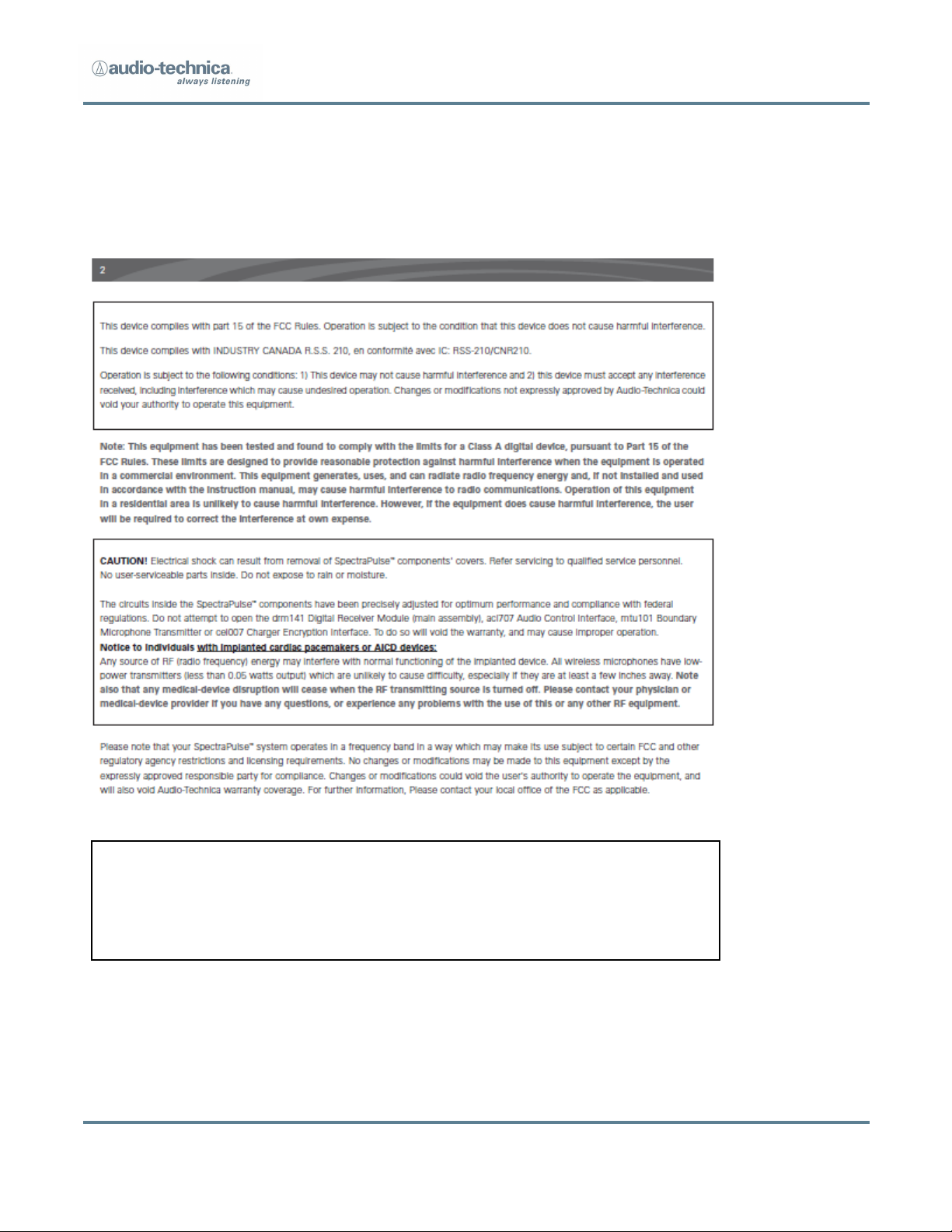
1. REGULATORY AND COMPLIANCE
Studio Broadcast System
Page 3 of 13
Page 4
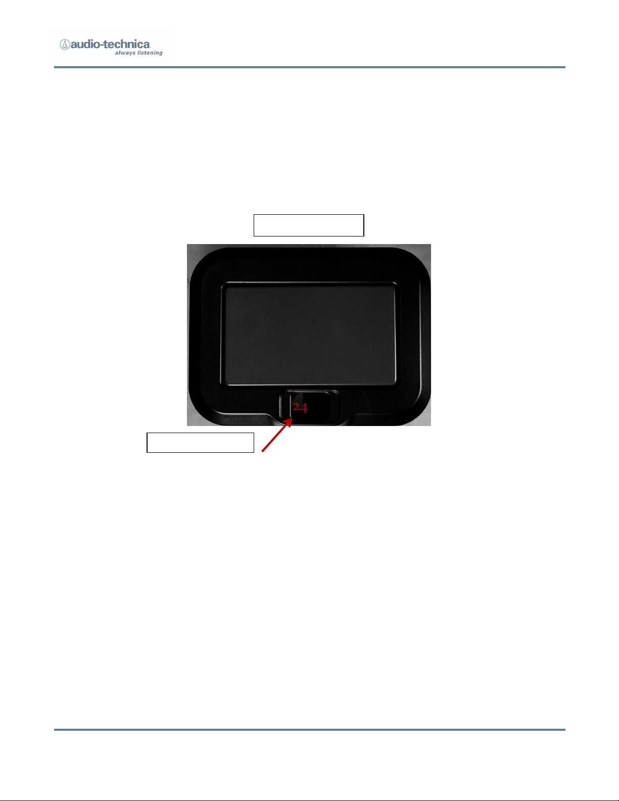
Receiver ID Number
Receiver Front View
2. RP32 UWB Receiver Module
Studio Broadcast System
A two digit display (7 Segment LED) is provided to automatically indicate the receiver
channel number when the RP32 is connected via a CAT5 cable to the corresponding
output channel of the MCU3224. This display serves as the unit’s power indicator. A
visible channel number also indicates that there is a full round-trip connection between
the RP and the MCU communications, confirming that the cable, the RP and the
corresponding MCU3224 channel are all operating appropriately. Should the user prefer
that the LED lights not be illuminated, there is a control option available on the MCU
“tools” screen which allows this RP display lights to be turned off.
Page 4 of 13
Page 5

Receiver Rear View
Studio Broadcast System
RJ45 Connector for Cat5 Cable
Connection to the RP32 is via an RJ45 jack on the rear. Once connected via RJ45 and
shielded CAT5 cable to an MCU, the RP is operational. There is no power switch, and no
further controls necessary. The MCU3224 supplies operating power and control over RP
functions/preferences is available via the tools screen of the MCU3224.
A choice of 2 mounting threads are available on the rear of the RP32. The inserts mate
with either 5/8”-27 thread or ¼”-20 thread adapters.
Page 5 of 13
Page 6

Studio Broadcast System
3. Positioning and Set Up
3.1. Positioning
When considering where to place RP32 Receiver Modules, it is useful to think of them as
“lights” with which you are attempting to cover and entirely fill a space. A rough
guideline of coverage pattern is shown below. This guideline is only a starting point. The
effects of multipath both to and from the RP32 are very beneficial and create additional
paths which “fill in” the coverage area. Although the system will work with only a single
RP32 picking up and communicating with a BP24 beltpack, we recommend that you
position the RP32s such that you have a minimum of 2 actively receiving the BP24 signal
at all times, and preferably a minimum of 3. There is no signal to add, subtract, or
interfere, so the more RP32s that communicate with and receive a BP24 the better.
Think of it as an up to 32-way digital diversity. All RP32s process all of the possible 24
channels of BP24 transmitters at all times. It does not matter which RP32 picks up a
signal or sends a signal. No pairing or other coordination is required. Once power is
applied to an RP32, it will automatically begin sending sync pulses to BP24 transmitters
(whether or not they are present) and they will look to receive a signal from a BP24
transmitter on the correct TDMA time slot.
A note about physical obstacles: Since this system operates in a very high frequency
range, the wavelengths are very short. That means that it is possible for them to “pass
through” porous materials. Although it is not optimum, it is sometimes possible to place
RP32s behind a surface if that surface will still allow the small 6GHz wavelength to pass.
A metallic or glass or stone surface is highly reflective and is beneficial for creating
supporting multipath, but it will not allow signals to pass through.
Page 6 of 13
Page 7

Studio Broadcast System
(drawing not to scale)
The red areas indicate a likely direct connection path for a single RP32. It is important to
note that there are a number of side lobes (may depend upon placement) and that
there is pick up and reception to the rear. The more typically expected active space is
indicated via the blue dashed lines.
Page 7 of 13
Page 8

Studio Broadcast System
Mode Swap Button
Σ Mode Select
3.2. Matrix Screen - Receiver Measurement
The matrix screen allows the user to visualize specific connections between 32 possible
receivers and 24 possible transmitters. There are two modes: Receiver Test and
Transmitter Test.
In the receiver test mode the user selects a source transmitter - blue buttons on the
right side of the screen - and the screen on the left indicates the active receivers
currently linked to that transmitter. Active receivers which have been plugged into the
system are indicated with a blue square; green fill indicates a link to the selected
transmitter. It is best if at least 3 RP32s indicate a green “linked” status to a BP24
transmitter at all times. This screen is useful for experimenting with RP32 placement in
order to determine the best coverage.
Page 8 of 13
Page 9

Studio Broadcast System
The Σ button is used to view receivers that are connected to ANY active transmitter
rather than just a single transmitter. This mode is used to test which receivers are most
effective in a given set up, and may also assist in receiver placement.
When the user selects the matrix screen, the system will first check for added receivers;
without interrupting the operation of the active receivers or the audio output. This
gives the user a way to add receivers while the system is in active operation. If the user
plugs in a receiver it will not be active until the system goes through this process.
Pressing the mode swap button switches to Transmitter measurement mode.
4. System QUICK START
Using a shielded CAT 5 cable (may be used with up to 1,000 feet of cable per
channel) terminated with a standard RJ45 connector, plug the cable into the RJ45
input jack on the rear of at least RP32 receiver. Connect the other end of the CAT
5 cable to the RJ45 input jack on the rear of the MCU3224 main control unit. You
may connect up to 32 RP32 receivers by connecting them into the corresponding
channel output (1-32) found on the rear of the MCU.
You do not need to turn the RP on. It receives power via the CAT 5 cable
from the MCU 3224. The RP display should immediately light and display
the channel output number to which it has been connected on the MCU.
Apply power to the MCU3224 by connecting at least one IEC cable to AC wall
supply.
Press the front panel “power” button.
The power light(s) corresponding to the IEC cable input will be visible on the
front panel (one red and one blue), and the GUI screen will illuminate and
enter a “set-up” mode while the system is normalizing and preparing for
operation.
Page 9 of 13
Page 10

Once the system is available for operation, the GUI screen will display a
“HOME SCREEN.”
On the left-hand side of the screen, select the “Matrix” button:
Studio Broadcast System
This will allow the user to view and confirm that the desired number of RPs are
connected to the system with the desired channel # assignments.
Place 2 x AA batteries into a BP24 beltpack transmitter and slide the internal
power switch into the on position.
Page 10 of 13
Page 11

Studio Broadcast System
Ensure that the BP24 system ID is the same as the System ID of the
MCU3224 (system will turn on in “default” system ID 1 for all devices). The
System ID is visible in all screens on the left-hand side of the display for
“navigation.”
Select the BP24 channel for operation (1 through 24)
Select the desired BP24 gain level
Ensure that the BP24 front surface is facing the RP32 front surface, and that they
are located somewhat in proximity to each other and roughly in a line-of sight
orientation. (Note that the distance of operation can be 90’ or more, depending
upon the particular operating environment, and line of sight operation is not
strictly or fully required due to positive effects of multi-path. However, with only
a single RP connected to the system, the “multiple coordinated receiver diversity”
is not in operation. Thus, line of sight and proximity are more important to stable
operation for initial set-up with only a single RP).
Page 11 of 13
Page 12

Studio Broadcast System
Return to the MCU and select the “home screen”
The BP24 that has just been turned on should be shown in the display on the
channel number that you have set via the BP24 channel selection process.
Press the GUI on the displayed channel to highlight/select the channel of the BP24
that you are operating. This will allow all information about this particular channel
to be observed on the other screens. It also selects this particular channel for
output to the front-mounted headphone monitor jack.
You may now listen to your selected beltpack, or if you prefer, you can observe its
operation characteristics by selecting the “transmitter detail” button:
Repeat this process for as many RP32s and BP24s as needed for the application.
No frequency or channel coordination is required. Simply ensure that only one
beltpack channel is in operation for each channel (up to 24) in each system ID. (Do
not attempt to set 2 BP channels to the same channel # in the same system. The
system will not operate).
Page 12 of 13
Page 13

Studio Broadcast System
Page 13 of 13
 Loading...