

Page 1
wireless
wireless
wireless
wireless
wireless
M3
Wireless In-Ear Monitor System
Set-up and Operation Pages 2-17
Installation et utilisation Pages 18-33
Configuración y funcionamiento Páginas 34-49
Configuração e operação Páginas 50-65
Impostazioni e Utilizzo Pagine 66-81
Einrichtung und Betrieb Seiten 82-97
Opstelling en gebruik Pagina 98-113
!
0168
P52002_M3-System_OM 2/27/08 9:08 AM Page 1
Page 2
WARNING!
USE AS LOW A VOLUME AS POSSIBLE. PERMANENT HEARING DAMAGE
CAN RESULT FROM USING THIS SYSTEM AT EXCESSIVE VOLUMES.
For safe operation of this in-ear monitor system, do not listen at excessive
sound pressure levels.
Most national safety and health administrations have established guidelines
for maximum time being exposed to sound pressure levels before hearing
damage occurs.
85 dB(A) SPL at 8 hours
88 dB(A) SPL at 4 hours
91 dB(A) SPL at 2 hours
94 dB(A) SPL at 1 hour
97 dB(A) SPL at 30 minutes
100 dB(A) SPL at 15 minutes
120 dB(A) SPL — avoid or hearing damage may occur
In live settings it is difficult to make exact measurements of Sound
Pressure Levels (SPL) present at the eardrum, which is affected not only
by the In-Ear Monitor volume, but by ambient sound on the stage and
other factors.
To protect your ears from hearing damage:
• Use the in-ear monitor system at the lowest volume possible; turn up
the volume only enough to hear
• Be aware that ringing in your ears may indicate that the volume is set
too high.
• Have your ears examined regularly by an audiologist.
• If wax builds up in your ears, stop using the in-ear monitor system
until you have seen an audiologist.
• To avoid infections, use an antiseptic to wipe the earphones before
and after using the system.
• Stop using the earphones if you experience ear discomfort or infection.
This device complies with the European R&TTE directive 1999/05/EC.
Operation is subject to the condition that this device does not cause
harmful interference. For Licensing information, please contact your local
dealer or radio authority.
This device complies with part 15 of the FCC Rules. Operation is subject to
the condition that this device does not cause harmful interference.
This device complies with INDUSTRY CANADA R.S.S. 210, en conformité
avec IC: RSS-210/CNR210.
Operation is subject to the following conditions: 1) This device may not cause
harmful interference and 2) this device must accept any interference received,
including interference which may cause undesired operation. Changes or
modifications not expressly approved by Audio-Technica could void your
authority to operate this equipment.
2
Notice to individuals with implanted cardiac pacemakers or AICD
devices: Any source of RF (radio frequency) energy may interfere with
normal functioning of the implanted device. All wireless microphones have
low-power transmitters (less than 0.05 watts output) which are unlikely to
cause difficulty, especially if they are at least a few inches away. However,
since a “body-pack” mic transmitter typically is placed against the body, we
suggest attaching it at the belt, rather than in a shirt pocket where it may
be immediately adjacent to the medical device. Note also that any medicaldevice disruption will cease when the RF transmitting source is turned off.
Please contact your physician or medical-device provider if you have any
questions, or experience any problems with the use of this or any other RF
equipment.
CAUTION! The circuits inside the receiver and transmitter have been precisely
adjusted for optimum performance and compliance with federal regulations.
Do not attempt to open the receiver or transmitter. To do so will void the
warranty, and may cause improper operation.
Warning: To prevent fire or shock hazard, do not expose this appliance to
rain or moisture.
• To avoid electrical shock, do not open the cabinet. Refer servicing to
qualified personnel only.
• Do not expose this apparatus to drips and splashes.
• Do not place any objects filled with liquids such as vases on the apparatus.
• Do not install this apparatus in a confined space such as a bookcase or
similar unit.
• The apparatus should be located close enough to the AC outlet so that you
can easily grasp the AC adapter at anytime.
Dispose of batteries in an environmentally responsible manner according
to the local laws and regulations of your region. Some batteries may be
recycled, and may be accepted for disposal at your local recycling center. If
you are not able to identify the applicable rules in your area, please check
the instructions of the battery manufacturer.
Do not dispose of batteries in a fire or trash incinerator, or leave batteries
in hot places such as an automobile under direct sunlight. Do not store
batteries near an oven, stove, or other heat source.
About RF Interference
Please note that wireless frequencies are shared with other radio services.
According to Federal Communications Commission regulations,
“Wireless microphone operations are unprotected from interference from
other licensed operations in the band. If any interference is received by
any Government or non-Government operation, the wireless microphone
must cease operation...” If you need help with operation or frequency
selection, please contact your local dealer or Audio-Technica. Extensive
wireless information also is available at www.audio-technica.com.
Warning—Use as low volume levels as possible.
To prevent damage to your eardrums, never use this system at excessive
volume levels. Listening to loud sounds for an extended period may
cause temporary or permanent hearing damage.
P52002_M3-System_OM 2/27/08 9:08 AM Page 2
Page 3
EN
M3 System Components
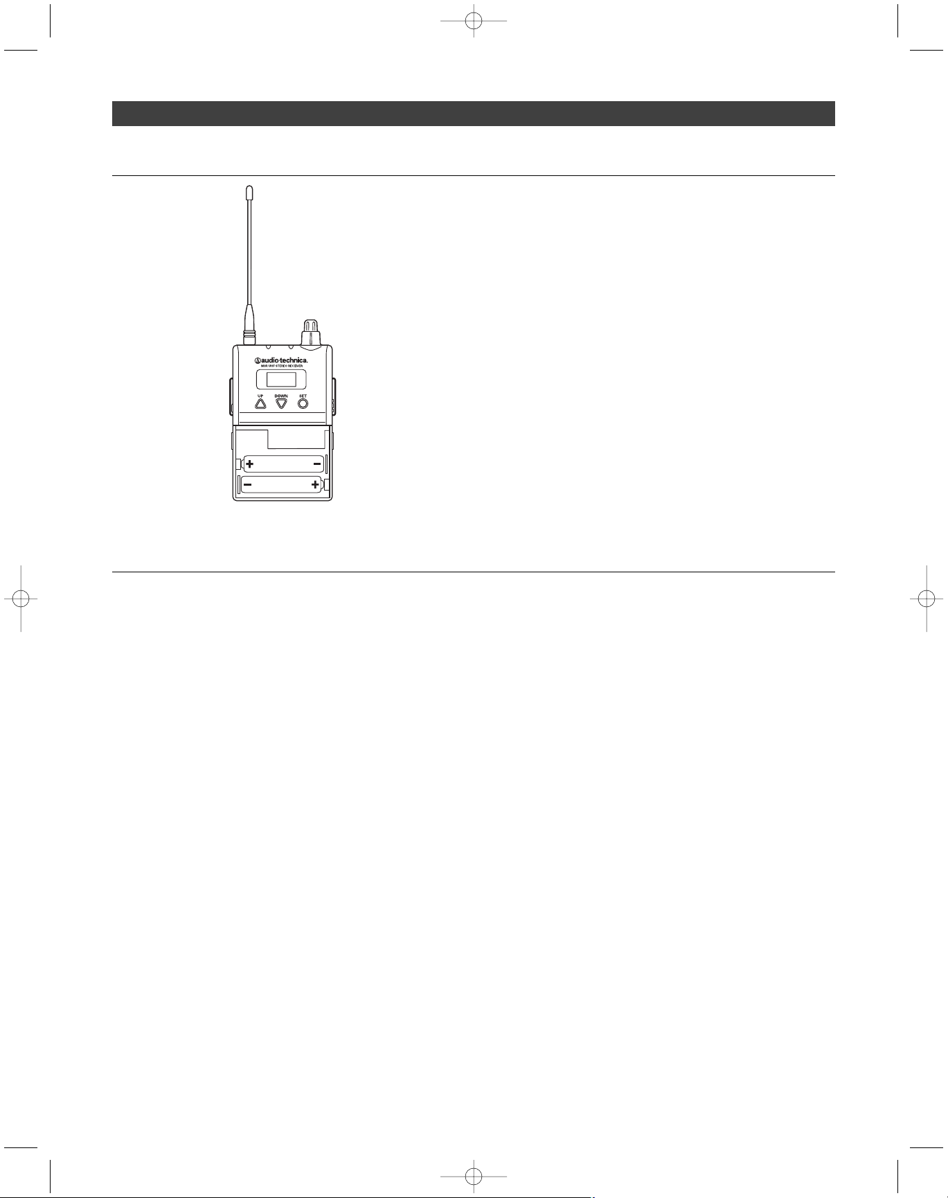
M3R
UHF Stereo Receiver
M3T
UHF Stereo Transmitter with detachable
antenna and AC adapter
EP3
Dynamic Earphones
3
Quick-start guide
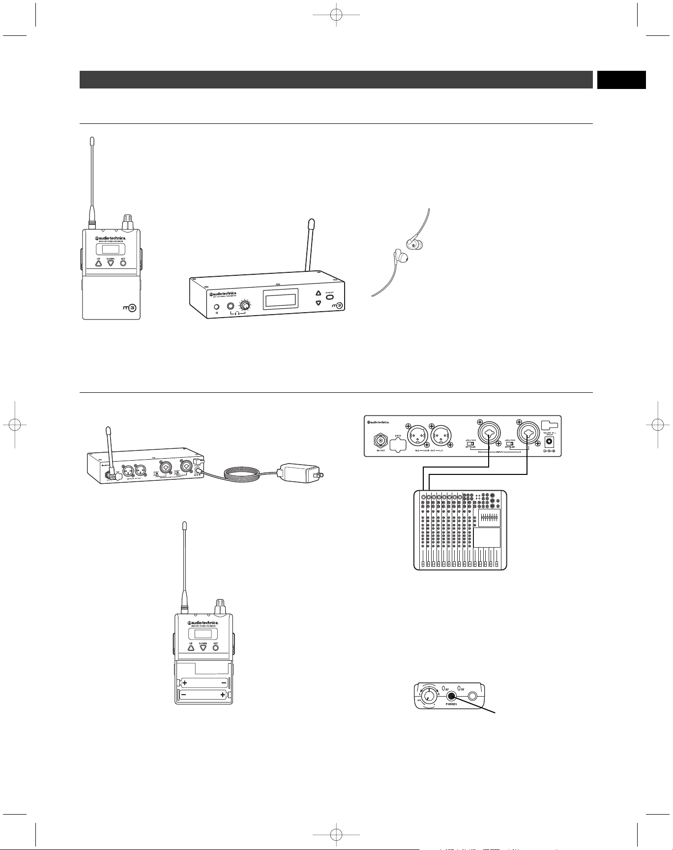
1. Plug in the included AC adapter and connect to transmitter’s DC input.
2. Insert 2 AA batteries in the M3R Stereo Receiver following polarity
as indicated.
3. Power on M3R Stereo Receiver with volume in minimum position;
power on M3T Stereo Transmitter.
4. Set M3R Stereo Receiver and M3T Stereo Transmitter to the same
frequency.
(See page 11.)
5. Power off receiver and transmitter.
6. Connect audio source(s) to inputs on the rear panel of the transmitter.
7. Power on M3T Stereo Transmitter.
8. Adjust attenuator on rear panel of M3T Stereo Transmitter to
appropriate level.
(See page 5.)
9. Adjust trim level of M3T Stereo Transmitter, if needed.
(See page 12.)
10. Plug supplied Dynamic Earphones into earphones locking output
jack on M3R Stereo Receiver. NOTE: Do not put the earphones
in your ears at this point.
11. Turn on receiver with volume in minimum position.
12. With volume on receiver at minimum position, put earphones into
your ears and gradually increase volume until appropriate level is
reached.
P52002_M3-System_OM 2/27/08 9:08 AM Page 3
Page 4

4
Thank you for buying the Audio-Technica M3 Wireless In-Ear Monitor
System. This feature-rich in-ear monitor system is designed to provide
you with comfortable high-fidelity sound on stage.
The M3 is a frequency-agile in-ear monitor system designed to make
stage monitoring more effective, comfortable, portable, and intelligible.
The M3R Stereo Receiver allows the user to create and control his/her
own mix on stage with Personal Mix Control that offers independent
control of volume and mix at the receiver. The M3T Stereo Transmitter
offers two
1
/4"/XLR combo input connectors into which users can connect
line-level inputs (from a mixing console, for example). The M3T Stereo
Transmitter also offers a headphone output that allows you to monitor
transmitter input signals directly. The transmitter and receiver each
offer an LCD information display that provides step-through menus for
setting preferences. The supplied earphones are equipped with a
proprietary Audio-Technica dynamic driver offering a full frequency
response and richly detailed high-fidelity sound. The clean, articulate
mix allows performers to hear themselves at comfortable SPLs. The
earphones come with three sizes of flexible rubber eartips and a
universal-fit foam tip for a custom fit, increased isolation and longwearing listening comfort.
Note: M3 “L” Band receivers must be used only with “L” Band
transmitters; the same holds true for M3 “M,” “E,” and “F” Band
receivers and transmitters. For multiple-channel applications, as
many as 16 systems may be used together per frequency band.
M3 Wireless In-Ear Monitor System – Introduction
System Features
• High-fidelity sound with clean, articulate mix allows you to
hear yourself better at lower volumes
• Over 1250 selectable UHF channels with automatic frequency
scanning
• Up to 16 simultaneous systems per frequency band
• Three receiver modes: Personal Mix, stereo, and mono
• Personal Mix Control allows you to adjust your own mix on stage
• LCD information display offers step-through menus for setting
preferences
• XLR loop output (true pass-through) connects signal to mixing
console, additional IEM system or recording device with no
signal degradation
• Adjustable squelch eliminates annoying static
• Pilot tone protects against RF interference when the transmitter
is turned off
• Three-stage limiter (defeatable) helps protect your hearing from
sudden peaks
• Portable system is quick to load and set up
• Reduces on-stage audio clutter for better overall mix & less
feedback
• Use any number of M3R Stereo Receivers on the same frequency
• Earphones with proprietary dynamic driver offer full frequency
response and outstanding isolation
• Earphones feature personal fit with 3 sizes of rubber eartips
plus an ear-conforming foam tip
• Selectable auxiliary input offers connection point for ambient
microphone, click track, or other mic- or line-level input.
P52002_M3-System_OM 2/27/08 9:08 AM Page 4
Page 5
EN
5
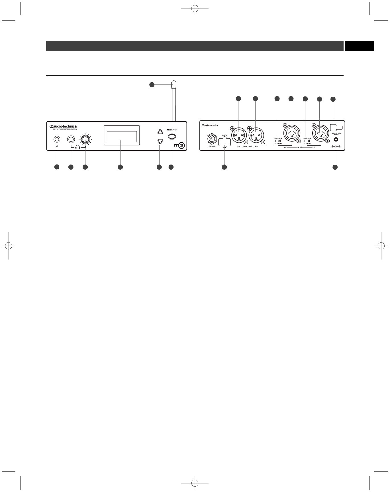
M3T Transmitter Controls
(front panel) (rear panel)
1. Power switch. Depress once to turn on. Depress again to turn off.
2. Headphone output.1/4" TRS jack provides monitoring of audio feed
at the transmitter. Plug in either a mono or stereo headphone.
3. Headphone level control. Adjusts level of monitor headphones;
affects 1/4" headphone jack only. Does not affect transmitter audio
output.
4. Liquid crystal display. Indicates control settings and operational
readings. It is also used with the Mode/Set and Up/Down arrow
buttons to change user-configurable functions. See page 7 for details.
5. Up/Down buttons. Use with the Mode/Set button to step through
menus, select operating frequency and edit receiver function choices.
6. Mode/Set button. Use with the Up/Down arrow buttons to step
through menus, choose operating frequency and select receiver
function options.
Two distinct operations are associated with this button:
Touch:
A momentary press of the Mode/Set button is used to
enter Menu mode, to enter Edit mode, or to Escape without
making any changes to current settings.
Hold:
A press and hold (about two seconds) of the Mode/Set button
is used to accept a new setting when the receiver is in Edit mode
or to save the current settings.
7. Detachable flexible antenna. Detachable antenna transmits to
receivers.
8. Data port. For factory use only.
9. Loop output. The R/2 XLR jack duplicates the unprocessed signal
of the R/2 input; the L/1 XLR jack duplicates the unprocessed
signal of the L/1 input. Not affected by front panel settings.
10. Attenuators. Offer -20 dB, -10 dB, and 0 dB attenuation for each
input.
11. Inputs. Combination input jacks offer both XLR and 1/4" jacks.
12. DC input. Plug the included power supply in here.
13. Cord hook. Loop the small DC cord around the cord hook to keep
the DC plug from pulling out accidentally.
Phantom power
The transmitter does not provide phantom power, but it does allow
phantom power to pass through from your phantom power supply to a
device plugged into either input jack.
CAUTION: If connecting instruments to a mixing console through
the transmitter loop output, then use a direct box to prevent
damage to your instruments and/or equipment from the mixing
console’s phantom power; i.e. hook your instrument into a direct
box, then hook your direct box into the transmitter.
10 11
13
9
7
1
8
12
2
9
10
11
3 4 5 6
P52002_M3-System_OM 2/27/08 9:08 AM Page 5
Page 6
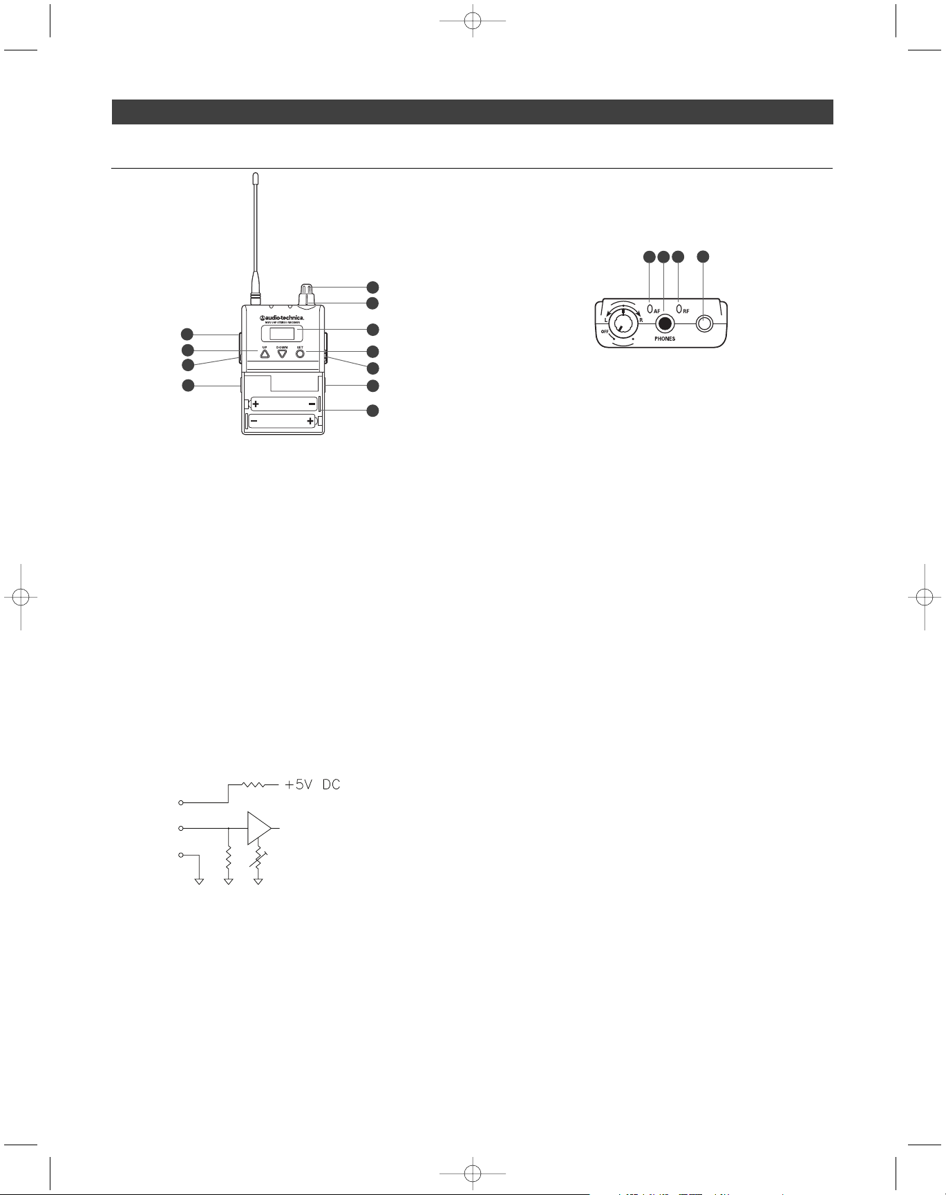
M3R Receiver Controls
1. On/off volume knob. Turn inner knob to the right; turns on with
click. Turn volume up with clockwise turn; turn volume down with
counterclockwise turn.
2. Balance control. 12 o’clock position offers equal left (L/1) and right
(R/2) level in both ears. In typical setups, turn the knob counterclockwise from the 12 o’clock position to hear more of L/1 in both
ears; turn the knob clockwise from the 12 o’clock position to hear
more of R/2 in both ears.
3. Earphones locking output jack. Connect your supplied earphones
to this 3.5 mm locking jack.
4. AF peak indicator. Illuminates orange to indicate audio signal is at
peak level.
5. RF indicator. Illuminates green to indicate RF signal is present.
6. Removable flexible antenna. Receives RF signal from the transmitter.
7. Selectable aux input. Connect a 3.5 mm line or mic level input to
this auxiliary input. (Mic or Line level is selectable by the Receiver’s
LCD information display,
Aux Level
menu; see
Aux Level
, page 9.)
Note: If you connect a stereo source (such as an MP3 player) into
the M3R Stereo Receiver’s Aux Input, be certain to use a mono
adapter to protect your equipment from the DC voltage that is
applied to the ring of the stereo connector.
8. Aux input on/off switch. Slide tab in direction of “On” to enable
the Aux input. Slide tab in direction of “Off” to disable the Aux input.
9. Belt clip. Attach the receiver to your belt or guitar strap with this
belt clip.
10. Battery door release. Slide tabs in direction of arrows to open
battery compartment door.
11. Battery compartment. See
How to install batteries in your M3R
Stereo Receiver
, page 10.
12. Liquid crystal display (with timed backlight). Indicates control
settings and operational readings. Backlight, on when receiver is
first turned on, times out after about 25 seconds; touch Set or
either of the Up/Down arrow buttons to turn the backlight on at
any time.
13. Up/Down arrow buttons. Use Up or Down arrow buttons with
the Set button to step through menus, select operating frequency
and edit receiver function choices.
14. Set button. Use with the Up/Down arrow buttons to step through
menus, choose operating frequency and select receiver function
options.
Two distinct operations are associated with this button:
Touch:
A momentary press of the Set button is used to enter
Menu mode, to enter Edit mode, or to Escape without making
any changes to current settings.
Hold:
A press and hold (about two seconds) of the Set button is
used to accept a new setting when the receiver is in Edit mode
or to save the current settings.
6
2
1
4
6
7
13
14
RING
TIP
SLEEVE
11
12
9
8
10
10
3
5
P52002_M3-System_OM 2/27/08 9:08 AM Page 6
Page 7
7
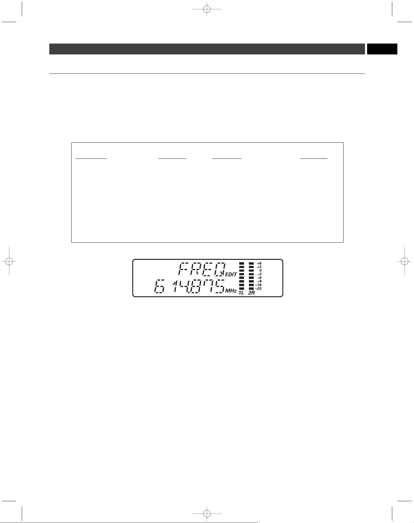
To access the M3T Stereo Transmitter’s user-changeable functions,
Touch the Mode/Set button. The top line of the transmitter display
shows “
FREQ
”. Touch the Down arrow button to scroll through the
functions that may be changed. Note that for Frequency, Trim, RF
Power, HP Out, the display’s lower line indicates the current setting
for the given function.
To change a transmitter function, when the function to be edited is
displayed,
touch
the Mode/Set button. The small word “
EDIT
” will flash
in the display.
Touch
the Up/Down arrow buttons to scroll through the
available choices for the function, stopping on the desired choice.
Hold
the Mode/Set button to accept the new choice. “
STORED
” appears in
the display when the choice is accepted. The transmitter then returns to
Menu mode. Continue this process until all desired function-setting
changes are complete. Note: To escape from Edit mode without
making any changes,
touch
the Mode/Set button. “
ESCAPE
”
appears briefly in the display, and the transmitter returns to
Menu mode.
EN
How to make setting changes on the M3T Stereo Transmitter
M3T Stereo Transmitter Functions
Function Menu Default Value Choices (Edit) Wrap-around*
▲▼ Frequency Lowest in band Over 1250 discrete frequencies Yes
▲▼ Group G1 - 1 G1 – G6 (16 channels each) Yes
▲▼ User U1 - 1 U1 – U3 (16 channels each) Yes
▲▼ Trim 0 0 – Unlimited No
▲▼ RF Power High Low, High Yes
▲▼ HP Out (Headphones Output) Stereo Stereo, L/R Mix Yes
▲▼ Program - Create custom frequency groups
▲▼ Reset - Choose OK to restore factory settings
▲▼ Quit (exit Menu) QUIT Press Mode/Set once to exit
* Continue in the same Up/Down direction and choices “wrap around” to the other end of the range.
Frequency (Transmitter)
Permits manual selection of a frequency. See
How to Select a
Frequency
, page 11.
Group (Transmitter)
Permits selection of frequency groups with pre-coordinated channels.
There are six frequency groups, each offering 16 pre-coordinated
channels. See
How to Select a Frequency
, page 11.
User (Transmitter)
Permits selection (optional) from among three user-created frequency
groups. See
How to Select a Frequency
, page 11.
Trim (Transmitter)
Controls level of both inputs (L/1 and R/2). Trim levels are set at the
factory to the maximum position (0); adjust if necessary. See
Setting
Levels
, page 12.
RF Power Adjustment (Transmitter)
Allows you to set RF power to “
RF HI
” or “
RF LOW
”. The default
setting is “
RF HIGH
.” When the setting you prefer is shown,
Hold
the
Mode/Set button.
Headphones Output (Transmitter)
Allows you to switch headphones output between Mix and Stereo. In
the Stereo setting, the L1 signal goes to the left earphone; the R2
signal goes to the right earphone. In the Mix setting, a combined signal
from both the L/1 and R/2 inputs goes to both earphones. When the
setting you prefer is shown,
Hold
the Mode/Set button.
Program (Transmitter)
In the event that the preprogrammed frequency groups (available under
the Group menu) do not meet your requirements, Audio-Technica
allows you to program custom frequency groups. See
How to Select a
Frequency
, page 11.
Reset (Transmitter)
Allows you to reset all transmitter functions to their factory-default
values.
Hold
the Mode/Set button while “
RESET
” is displayed in the
LCD window. At the prompt “
OK?” hold
the Mode/Set button again.
Factory-default settings will be restored.
Quit (Transmitter)
To exit the Edit mode, press the Down arrow until “
QUIT
” is displayed
in the LCD window. Then press the Mode/Set button once to exit the
menu. The “AF” scales will reappear in the window, indicating the
return to normal operation.
P52002_M3-System_OM 2/27/08 9:08 AM Page 7
Page 8
8
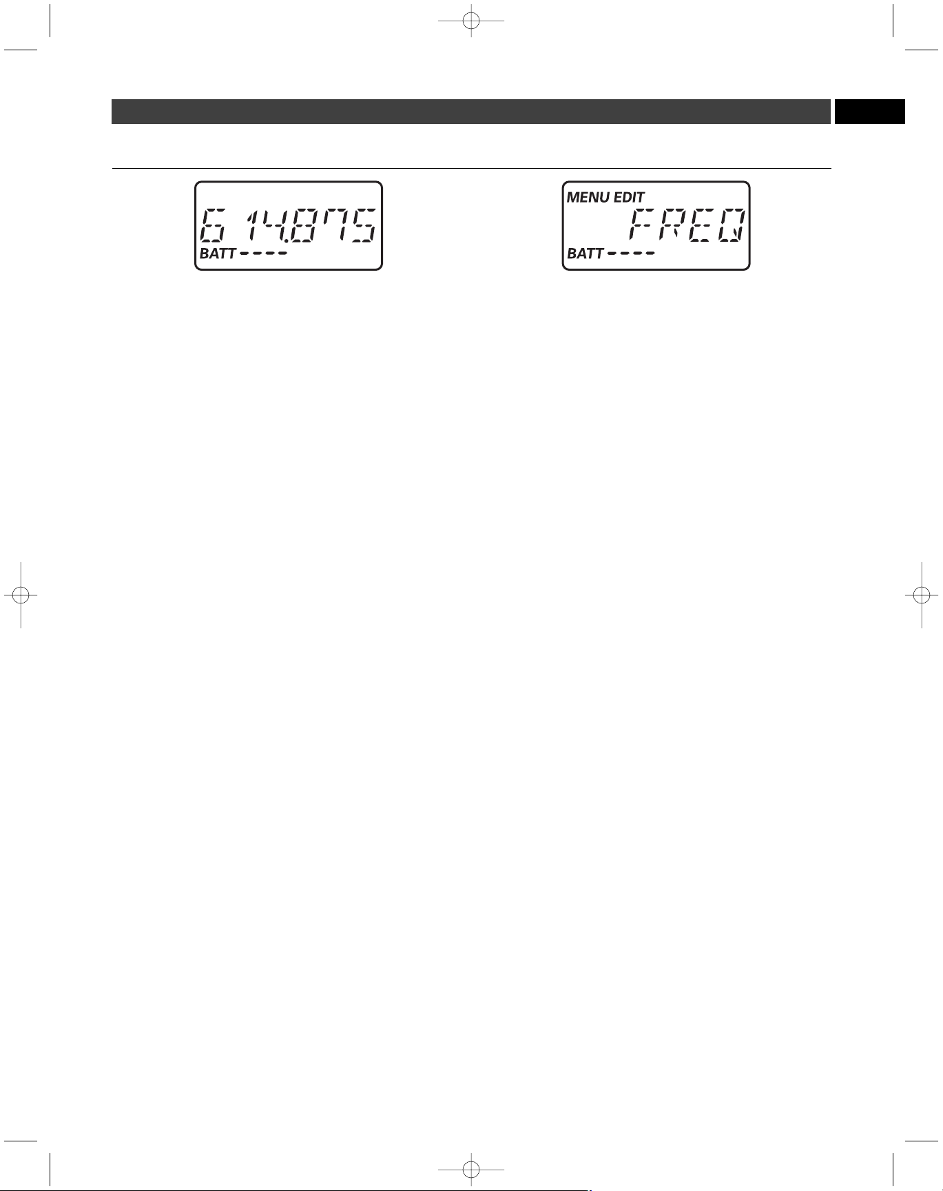
To access the M3R Stereo Receiver’s user-changeable functions,
Touch
the Set button. The top line of the transmitter display shows “
FREQ
”.
Touch
the Down arrow button to scroll through the functions that may
be changed. (See the chart below.)
To change a receiver function, when the function to be edited is displayed,
touch
the Set button. (Note: When the M3R Stereo Receiver is first
powered on, the LCD’s timed backlight is on. After the backlight
has timed out, a
touch
of the Set or Up/Down arrows turns the
light on again. In this case, you will need to
touch
the Set button
twice in order to change a receiver function, since the first touch
will simply turn the backlight on.)
The small word “
EDIT
” will appear in the display.
Touch
the Up/Down
arrow buttons to scroll through the available choices for the function,
stopping on the desired choice.
Hold
the Mode/Set button to accept the
new choice. “
STORED
” appears in the display when the choice is
accepted. The receiver then returns to Menu mode. Continue this
process until all desired function-setting changes are complete. Note:
To escape from Edit mode without making any changes,
touch
the
Mode/Set button. “
ESCAPE
” appears briefly in the display, and the
receiver returns to Menu mode.
How to make setting changes on the M3R Stereo Receiver
M3R Stereo Receiver Functions
Function Menu Default Value Choices (Edit) Wrap-around*
▲▼ Frequency Lowest in band Over 1250 discrete frequencies Yes
▲▼ Group G1 - 1 G1 – G6 (16 channels each) Yes
▲▼ User U1 - 1 U1 – U3 (16 channels each) Yes
▲▼ Scan **/*** No value Scan start --
▲▼ Limiter 3 (maximum limiting) 3, 2, 1, Off Yes
▲▼ Squelch 0 Off, -1, 0, 1, 2 No
▲▼ Mode Stereo Stereo, Mono Yes
▲▼ Output Stereo Stereo, L/R Mix Yes
▲▼ Aux level Line Line, Mic Yes
▲▼ Mic Volume (if Aux set to Mic) 1 1 – 16 No
▲▼ Program - Create custom frequency groups
▲▼ Reset Choose OK to restore factory settings
▲▼ Quit (exit Menu) QUIT Press Mode/Set once to exit
* Continue in the same Up/Down direction and choices “wrap around” to the other end of the range.
Continued on page 9
P52002_M3-System_OM 2/27/08 9:08 AM Page 8
Page 9
9
EN
Frequency (Receiver)
Permits manual selection of a frequency. See
How to Select a
Frequency
, page 11.
Group (Receiver)
Permits selection of frequency groups with pre-coordinated channels.
See
How to Select a Frequency
, page 11.
User (Receiver)
Permits selection (optional) from among three user-created frequency
groups. See
How to Select a Frequency
, page 11.
Scan (Receiver)
Allows you to scan automatically for an available frequency. See
How
to Select a Frequency
, page 11.
Limiter (Receiver)
Limits output level to earphones. Choices are 3,2,1, OFF. Factory
setting is 3 (maximum limiting).
Touch
the Up/Down arrow buttons to
change the setting. When the setting you want to select is shown,
Hold
the Set button. IMPORTANT: Leave limiter at setting 3. This
setting protects your hearing from unexpected signal peaks; it does
not protect your hearing from long-term exposure to high SPLs.
Squelch Control (Receiver)
Allows you to adjust squelch on receiver, eliminating unwanted
background RF noise. Maximum squelch setting (minimum range) is 2;
OFF is no squelch (maximum range).
Touch
the Up/Down arrow buttons to change the setting. When the setting you want to select is
shown,
Hold
the Set button.
Mode (Receiver)
Permits changing the receiving mode from Mono to Stereo.
Touch
the
Up/Down arrow buttons to change the setting. When the setting you
want to select is shown,
Hold
the Set button. (See
Output
, below.)
Output (Receiver)
Allows you to switch headphones output between Mix and Stereo. In
the Stereo setting, the L1 signal goes to the left earphone; the R2
signal goes to the right earphone. In the Mix setting, a combined signal
from both the L/1 and R/2 inputs goes to both earphones. When the
setting you prefer is shown,
Hold
the Set button.
The Mode and Output menus are used together as follows:
Stereo Mode & Stereo Output
The Stereo/Stereo configuration is used as follows: the L/1 input signal
goes to the left earphone; the R/1 input signal goes to the right
earphone. Use the receiver’s balance control to adjust the stereo image.
See image A on page 14.
Stereo Mode & Mix Output
The Stereo/Mix configuration is used as follows: the signals from
both the L/1 and R/2 inputs go to both the left and right earphones.
Use the receiver’s balance control as follows: turn clockwise to
make R/2 louder and L/1 quieter; turn counterclockwise to make L/1
louder and R/2 quieter. (However you adjust the balance control,
both the left and right earphones will have the same total volume).
See image B on page 14.
Mono Mode (Output setting does not apply here; either Mix or
Stereo has the same result)
The Mono/Mix configuration is used as follows: there is only one
output from your mixer (connected to either the L/1 or R/2 input of
your transmitter). This signal will go to both left and right earphones.
When two-signal transmission is not required, use Mono Mode for
improved signal-to-noise performance. See image C on page 15.
Aux Level (Receiver)
Allows you to change the auxiliary input from mic level to line level.
When the setting you prefer is shown,
Hold
the Set button. Choose
mic level if you are connecting an ambient microphone (optional
Audio-Technica lavalier microphone) to the M3R Stereo Receiver’s
auxiliary input. Choose line level if you are connecting a click track or
other line-level source to the auxiliary input.
Note: If you connect a stereo source (such as an MP3 player) into
the M3R Stereo Receiver’s Aux Input, be certain to use a mono
adapter to protect your equipment from the DC voltage that is
applied to the ring of the stereo connector.
Mic Vol (Receiver)
If you have selected
Mic Level
(in the
Aux Level
menu above), the
Mic
Vol
menu allows you to adjust the volume of the ambient microphone
(optional Audio-Technica lavalier microphone or equivalent). 1 is the
lowest volume level; 16 is the highest volume level. When the setting
you prefer is shown,
Hold
the Set button. (Note: the
Mic Vol
menu does
not appear if you have selected
Line Level
in the
Aux Level
menu.)
Program (Receiver)
In the event that the preprogrammed frequency groups (available under
the Group menu) do not meet your requirements, Audio-Technica
allows you to program custom frequency groups. See
How to Select a
Frequency
, page 11.
Reset (Receiver)
Allows you to reset all receiver functions to their factory-default values.
Hold
the Set button while “
RESET
” is displayed in the LCD window.
At the prompt
OK? hold
the Mode/Set button again. Factory-default
settings will be restored.
How to make setting changes on the M3R Stereo Receiver (continued)
P52002_M3-System_OM 2/27/08 9:08 AM Page 9
Page 10
10
How to install the batteries in your M3R Stereo Receiver
Each M3R Stereo Receiver uses two 1.5V AA batteries, not included.
Alkaline type is recommended. Always replace all batteries. Make
certain the receiver power is Off before replacing batteries.
1. Open the battery compartment door by sliding tabs in the direction
of the arrows and rotating the door open.
2. Observe correct polarity as marked and carefully insert two fresh
1.5V AA alkaline batteries
3. Close the door, making certain the latches click securely in place.
Note: The M3R Stereo Receiver’s “fuel gauge” battery indicator
displays a maximum of four bar segments. When it flashes
“
LOW.BAT
”, the batteries should be replaced immediately to
ensure continued operation.
System Operation
Placement:
Location
For best operation, place the M3T Stereo Transmitter near the performance
location. The transmitter should be at least 1 meter (3 feet) from the
receiver. Keep antennas away from noise sources such as digital
equipment, motors, automobiles and neon lights, as well as away from
large metal objects. Audio-Technica recommends that you do not locate
the M3T Stereo Transmitter in the same rack with a wireless microphone
receiver.
System set-up:
1. Plug in the included AC adapter and connect to transmitter’s DC
input.
2. Insert two AA batteries in the receiver, observing polarity as indicated.
3. Power on your receiver (without earphones) with volume in
minimum position. Note: At this point, check to be certain the
RF indictor is not illuminated. If it is illuminated before you
have powered on the transmitter, this means the frequency
you have chosen is already in use. Choose another frequency.
4. Power on the transmitter.
5. Set the receiver and transmitter to the same frequency group and
frequency channel. (
See page 17.
) Note: Do not set more than
one transmitter to the same frequency.
6. Check the RF LED on your receiver to be certain it is illuminated.
(This indicates that it is receiving a signal from the transmitter.)
7. Power off both units (transmitter and receiver).
Audio set-up:
8. Connect audio source(s) to inputs on the rear panel of the
transmitter. There are two combination audio inputs on the back
panel; each offers both XLR and
1
/4" inputs. Use shielded audio
cable for the connection between the transmitter and the audio
source (mixer or instrument). Note: If you want to send the
audio signal through your transmitter (to another transmitter
or recording device, for instance), use the Loop output connectors
on the back of the M3T Stereo Transmitter. The R/2 XLR jack
duplicates the unprocessed signal of the R/2 input; the L/1 XLR
jack duplicates the unprocessed signal of the L/1 input. These
are not affected by front panel settings.
9. Turn on the transmitter.
10. Set the attenuator on rear panel of transmitter to appropriate level.
If AF level indicators (on right side of transmitter LCD) are consistently
at or above +3, set the attenuator to -10 or -20 dB or turn the trim
down for corresponding audio input.
11. Trim levels are set at the factory to the maximum position; adjust if
necessary. (
See page 12.
)
12. Plug earphones into jack on receiver. Turn the locking ring
clockwise until tight. NOTE: Do not put the earphones in your
ears at this point.
13. Turn on receiver with volume in minimum position.
14. With volume on receiver at minimum position, put earphones into
your ears and gradually increase volume until appropriate level is
reached.
P52002_M3-System_OM 2/27/08 9:08 AM Page 10
Page 11

11
EN
How to select a frequency
You have several choices of how to select a frequency on your M3T
Stereo Transmitter and M3R Stereo Receiver:
• select a frequency manually,
• select a preprogrammed frequency group and channel,
• create a custom frequency group,
• scan automatically (M3R Stereo Receiver only) for an available
frequency group and channel.
Note: Select a unique frequency for each M3T Stereo Transmitter
in use. Any number of M3R Stereo Receivers can be set to the
same frequency (as that of their associated transmitter) and
receive the same mix.
Note: On the M3R Stereo Receiver, the “Set” button has the same
function as does the “Mode/Set” button on the M3T Stereo Transmitter.
1. If you choose to manually select a frequency, use the FREQ
menu on the LCD window of the M3T Stereo Transmitter and
M3R Stereo Receiver.
When “
FREQ
” is displayed,
touch
the Mode/Set (or Set) button. The
small word “
EDIT
” appears in the display, indicating Edit mode.
Touch
the Up/Down arrow buttons to scroll through the available choices
for the first three digits of the frequency, stopping on the desired
choice.
Hold
the Mode/Set (or Set) button to accept the new choice.
Touch
the Up/Down arrow buttons to scroll through the available
choices for the last three digits of the frequency, stopping on the
desired choice.
Hold
the Mode/Set (or Set) button to accept the new
choice. “
STORED
” appears in the display when the choice is accepted.
The unit then returns to Menu mode. Note: To escape from Edit
mode without making any changes,
touch
the Mode/Set (or
Set) button. “
ESCAPE
” appears briefly in the display, and the
unit returns to Menu mode.
2. Instead of manually selecting a frequency, you may select a
frequency group and channel (Group 1 – Channel 1 through
Group 6 – Channel 16) via the GROUP menu on the LCD window
of the M3T Stereo Transmitter and M3R Stereo Receiver.
When “
GROUP
” is displayed,
touch
the Mode/Set (or Set) button.
The small word “
EDIT
” appears in the display, indicating Edit mode.
Touch
the Up/Down arrow buttons to scroll through the available
choices for the function, stopping on the desired choice.
Hold
the
Mode/Set (or Set) button to accept the new choice. “
STORED
”
appears in the display when the choice is accepted. The unit then
returns to Menu mode. Note: To escape from Edit mode without
making any changes,
touch
the Mode/Set (or Set) button.
“ESCAPE” appears briefly in the display, and the unit returns
to Menu mode.
Note: All channels within a given group are compatible. If you
are using multiple transmitters, set each transmitter to a different
channel within the same group.
3. In the event that the preprogrammed frequency groups (available
under the Group menu) do not meet your requirements,
Audio-Technica allows you to program custom frequency
groups as follows:
Hold
the Mode/Set (or Set) button while “
PROG
” is displayed in
the LCD window. The display will show the custom frequency group
number “U1” and channel “ 1”; change this field with the Up/Down
arrows (scrolling through 16 channels for each of three frequency
groups, U1 – U3, until you arrive at the group and channel number
you want to program.
Hold
the Mode/Set (or Set) button a second
time. The first three digits of the frequency will flash; you may
change this field with up-down arrows.
Hold
the Mode/Set (or Set)
button a third time. Now the second three digits of the frequency
will flash; you may change this field with the Up/Down arrows.
Hold
the Mode/Set (or Set) button again. The display will briefly show
“
STORED
”, and the unit will return to normal operation.
4. On the M3R Stereo Receiver, you also have the choice of using
the Automatic Frequency Scanning function to select a
frequency, as follows:
• When “
SCAN
” is displayed in the LCD window,
touch
the Set
button; then the word “
MENU
” will disappear from the window,
and the small word “
EDIT
” will appear in the display along with
the frequency group G1.
• Use the Up/Down arrow buttons to reach any of the following
scan groups: G1, G2, G3, G4, G5, G6, U1, U2, or U3.
• Press the Set button once to select one of these nine Scan groups
and begin the scan. The word “
SCAN
” will appear briefly in the
LCD window; then the lowest available channel in the selected
Scan group will appear in the LCD window.
• If you do not wish to use the frequency found, you may press the
Up or Down arrow. The Up arrow will scan upwards, the Down
arrow will scan downwards, from the frequency you are on.
• To activate a frequency selection,
press and hold
the Set button
until the word “
STORED
” appears in the LCD window. (If you do
not wish to complete this particular selection, just
press
the
Mode/Set button once. The word “
ESCAPE
” will appear briefly in
the window and the receiver will return to the Menu mode.)
• After you have activated your frequency selection, the word “
Menu
”
will reappear in the window, indicating the return to normal operation.
• If you are using multiple systems, after completing the first receiver's
scan and frequency selection, set the transmitter to the same
frequency; leave the transmitter On, and run the next receiver’s
automatic scan function. Always set a receiver-transmitter pair to
the same frequency before using the automatic scan function to
select a frequency for the next receiver. (When using multiple
transmitters, always use the same frequency group.)
Continued on page 12
P52002_M3-System_OM 2/27/08 9:08 AM Page 11
Page 12

12
How to select a frequency (continued)
Each transmitter/receiver system operates on a choice of over 1250
switch-selected frequencies per band. Available frequencies are shown
in the chart on page 17. When using multiple transmitters, always use
the same frequency group.
M3 “L” Band transmitters must be used only with “L” Band receivers;
the same holds true for all the frequency bands (i.e., always use
receivers and transmitters that operate in the same band). The Band
marking will be found on the antenna of both the M3T Stereo Transmitter
and M3R Stereo Receiver.
Note: Because these frequencies are shared with TV broadcasting
(depending on country of use), frequency selection is largely
dependent upon which TV broadcast channels are in operation
where the wireless system is to be used.
Squelch Control
The squelch control is preset at the factory, but can be adjusted if you
must use the system in a high RF interference area. If there is audio
output from the receiver when your transmitter is off, adjust the
squelch control so the system will receive the signal from your
transmitter but “squelch” or eliminate the unwanted background RF
noise. This adjustment will cause a reduction in useable range of the
wireless transmitter, so set the control to the lowest position which
reliably mutes the unwanted RF signals.
Setting Levels
Correct adjustment of transmitter audio input and receiver audio output
is important for optimum system performance.
The M3T Stereo Transmitter trim (volume) controls (See
Trim Control
,
page 7) have factory pre-set audio input levels. Factory setting is 0
(no attenuation). With a source plugged into the transmitter (at typical
levels), check the AF level indicator on the transmitter. If the AF is
consistently at +3 or above, it may be necessary to adjust the transmitter
trim until the AF level indicator is no longer consistently at high levels.
No further transmitter trim adjustments should be needed, as long as
the acoustic input does not change significantly.
Aux In jack
The M3R Stereo Receiver offers a 3.5 mm Aux In jack that allows you to
add another audio source, such as a click track, or ambient microphone
(optional Audio-Technica lavalier microphone).
• To use a condenser microphone as an ambient microphone, select
Mic Level from the Aux Level menu on the M3R Stereo Receiver
(See
Aux Level
, page 9); plug the microphone into the Aux In jack;
and adjust the Mic Volume as needed (See
Mic Vol
, page 9).
• To use the Aux In jack as a line-level input, select Line Level from
the Aux Level menu on the M3R Stereo Receiver (See
Aux Level
(Receiver)
, page 9); plug line-level source (a click track, for example)
into the Aux In jack. Note: If you connect a stereo source (such
as an MP3 player) into the M3R Stereo Receiver’s Aux Input,
be certain to use a mono adapter to protect your equipment
from the DC voltage that is applied to the ring of the stereo
connector.
P52002_M3-System_OM 2/27/08 9:08 AM Page 12
Page 13

EN
13
System Applications
The nature of in-ear monitoring allows for endless experimentation; the
M3 Wireless In-Ear Monitor System can be easily configured to meet
your individual needs. While there are countless ways to use the system,
we have illustrated some typical setups below.
Note: In conjunction with these setups, follow instructions for system
operation. (
See page 10.
)
3 Receiver Modes: Personal Mix Control, Stereo, Mono
The M3 Wireless In-Ear Monitor System offers three receiver modes:
Stereo setup: The signals from L/1 and R/2 are separate (not
mixed). The user hears L/1 through the left earphone, and R/2
through the right earphone. The user adjusts the relative level of
each signal via the M3R Receiver’s balance control.
Personal Mix Control: The signals from L/1 and R/2 are mixed.
The user hears the combined signal in both ears—and controls the
mix (by adjusting the relative strength of the L/1 and R/2 signals)
via the M3R Receiver’s balance control.
This is most often used when the transmitter receives two very
distinct mixes—such as band and vocal. During the performance,
the user can control how much vocal is heard relative to the band mix.
Mono setup: The mono setup is used when only a single mono
mix is available. The user hears that mix through both ears.
Stereo setup. See image A on page 14.
Basic stereo setup
1. On M3R Stereo Receiver:
Set STEREO Output;
Set STEREO Mode. (
See page 9
)
2. Create separate left and right band mixes using two aux channels
from your mixing console.
3. Connect one of these aux outputs from your mixing console to the
L/1 input on your M3T Stereo Transmitter; connect the second aux
output from your mixer to the R/2 input on your M3T Stereo
Transmitter.
4. Monitor the AF level indicators on front of transmitter to make
certain signal is not clipping. (Signal is clipped when the peak light is
on constantly.)
5. If necessary, use the trim control to adjust input level.
6. Use the balance control on your M3R Stereo Receiver to control
the left/right stereo image. (Turn the balance control to the left to hear
more of L/1; turn the balance control to the right to hear more of R/2.)
7. Adjust volume control to a comfortable, safe level. Note: Use
volume levels as low as possible.
8. (Optional). Use M3T Stereo Transmitter’s loop output to connect
L/1 and R/2 to a recording device.
9. (Optional). Insert Audio-Technica lavalier microphone (available
separately) into M3R Stereo Receiver to increase awareness of
ambient sound.
10. Any number of additional M3R Stereo Receivers can be set to the
same frequency and receive the same mix.
Personal Mix Control. See image B on page 14.
Typical two-channel operation using Personal Mix Control
1. On M3R Stereo Receiver:
Set MIX Ouput;
Set STEREO Mode.
2. Create a band mix with an aux channel of your mixing console.
3. On a separate aux channel of your mixing console, create a second
mix featuring vocals. (Alternatively, this second mix could feature
guitars, drums, keyboards, etc.)
4. Connect the band mix aux output to the R/2 input on your M3T
Stereo Transmitter.
5. Connect the vocal mix aux output to the L/1 input on your M3T
Stereo Transmitter.
6. Monitor the AF level indicators on front of transmitter to make
certain the signal is not clipping. (Signal is clipped when the peak
light is on constantly or distortion is heard.)
7. If necessary, use the trim control to adjust input level.
8. Turn the M3R Stereo Receiver’s balance control toward the left to
hear more vocal (L/1) in both ears; turn the receiver’s balance
control to the right to hear more band (R/2) in both ears.
9. (Optional). Insert Audio-Technica lavalier microphone (available
separately) into M3R Stereo Receiver to increase awareness of
ambient sound.
10. (Optional). Connect a midi click source (for drummers) to your belt
pack’s Aux Input.
11. Any number of additional M3R Stereo Receivers can be set to the
same frequency and receive the same mix.
Advanced two-channel setup (Personal Mix Control) Using direct
outputs and multiple M3 systems. See image C on page 15.
On M3R Stereo Receiver:
Set MIX Output;
Set STEREO Mode.
This setup enables each individual band member to control his/her
relative mix levels using the balance control on his/her M3R Stereo
Receiver. Turn the M3R Stereo Receiver’s balance control toward the
left to hear more vocal or instrument of choice level (L/1) in both ears;
turn the receiver’s balance control to the right to hear more band, (R/2)
in both ears.
Advanced two-channel stereo setup. See image D on page 15.
Multiple auxiliary sends and ambient audience microphones.
Note: Do not feed ambient microphones to main output of PA.
This setup enables you to create custom stereo mixes for each band
member using individual auxiliary outputs and IEM systems for each
band member.
P52002_M3-System_OM 2/27/08 9:08 AM Page 13
Page 14

14
) ) )
MIXER
Band Mix
Voc als
Left
(More Vocals)
M3R
Right
(More Band Mix)
AMBIENT MICROPHONE
(optional)
Band + Vocals Band + Vocals
( ( (
M3T
Input L/1
Input R/2
) ) )
MIXER
Band Mix Right
Band Mix Left
Left
M3R
Right
AMBIENT MICROPHONE
(optional)
Band Mix Right Band Mix Left
( ( (
M3T
Input L/1
Input R/2
Loop Out L/1
Loop Out R/2
RECORDING DEVICE
(optional)
B. Typical 2 Channel Set-up (Personal Mix Control)
A. Basic Stereo Set-up
P52002_M3-System_OM 2/27/08 9:08 AM Page 14
Page 15

15
EN
M3T CUSTOM MIX 2
(SYSTEM 2)
M3T CUSTOM MIX 3
(SYSTEM 3)
M3T CUSTOM MIX 1
(SYSTEM 1)
AMBIENT
MICROPHONES
) ) )
Input L/1
Input R/2
MIXER
Custom Mix 1 Right
Custom Mix 1 Left
Left
M3R
Right
SYSTEM 1
Custom Mix 1 Right Custom M ix 1 Left
( ( (
) ) )
( ( (
Left
M3R
Right
SYSTEM 3
( ( (
) ) )
Left
M3R
Right
SYSTEM 2
Input L/1
Input R/2
Input L/1
Input R/2
Input L/1
Input R/2
D. Advanced 2 Channel Stereo Set-up Multiple Aux Sends and Ambient Audience Mics
Custom Mix 2 Right Custom M ix 2 Left Custom Mix 3 Right Custom M ix 3 Left
Custom Mix 2 Right
Custom Mix 2 Left
Custom Mix 3 Right
Custom Mix 3 Left
Aux 1
Aux 2
Aux 3
Aux 4
Aux 5
Aux 6
P52002_M3-System_OM 2/27/08 9:08 AM Page 15
C. Advanced 2 Channel Set-up (Personal Mix Control Using Direct Outputs)
Band Mix
Vocal 1
Vocal 2
Aux
Direct Outputs
(More Vocal 1)
MIXER
M3R
SYSTEM 1
Left
Right
(More Band Mix)
AMBIENT MICROPHONE
(optional)
Guitar
Left
(More Vocal 2)
M3R
SYSTEM 2
Right
(More Band Mix)
AMBIENT MICROPHONE
(optional)
Left
(More Guitar)
M3R
SYSTEM 3
Right
(More Band Mix)
AMBIENT MICROPHONE
(optional)
Input L/1
Input R/2
Loop Out L/1
M3T (SYSTEM 1)
M3T (SYSTEM 2)
Loop Out R/2
Input L/1
Input R/2
Loop Out L/1
Loop Out R/2
Band + Vocal 1 Band + Vocal 1
( ( (
) ) )
Band + Vocal 2 Band + Vocal 2
( ( (
) ) )
Band + Guitar
( ( (
) ) )
Band + Guitar
Input L/1
Input R/2
Loop Out L/1
Loop Out R/2
M3T (SYSTEM 3)
Page 16

16
Specifications
†
Overall System
UHF Operating Frequencies
Band Frequency Range Number of Frequencies
Band E: 790.000 to 822.000 MHz 1281
Band F: 832.000 to 865.000 MHz 1282
Band L: 575.000 to 608.000 MHz 1321
Band M: 614.000 to 647.000 MHz 1321
Not all frequency bands available in all areas.
Please check with local regulations.
Minimum Frequency Step 25 kHz
Modulation Mode FM stereo
Maximum Deviation ±40 kHz
Dynamic Range 90 dB (typical), A-weighted
Total Harmonic Distortion <1% (at 1 kHz, ±20 kHz Deviation)
Operating Range 100 m (300'), typical
Open range environment with no interfering signals.
Operating Temperature Range -5° C (23° F) to 50° C (122° F)
Battery and LCD performance may be reduced at very low temperatures.
Frequency Response 60 Hz to 13 kHz (±3 dB)
Simultaneous Use 16 channels per band (maximum recommended)
For assistance with multi-band operation or other frequency
coordination issues, please contact your regional
Audio-Technica customer service representitive.
Receiver
Receiving System Double conversion superheterodyne
RF Sensitivity 20 dBuV (at 60 dB S/N ratio, 50 ohms termination)
Headphone Output Connector 3.5 mm TRS stereo phone jack
Headphone Output Power 65 mW (at 32 ohms)
Antenna Input SMA-type, 50 ohms
Aux Input Connector 3.5 mm TRS stereo phone jack
Batteries 2 x 1.5V AA (not included)
Battery Life 8 hours (alkaline)
Depending on battery type and use pattern.
Dimensions 70.0 mm (2.76") W x 25.0 mm (0.98") D x 110.0 mm (4.33") H
Net Weight 133 g (4.7 oz), without batteries
Accessories Included EP3 earphones; flexible antenna
Transmitter
RF Power Output 10 mW/50 mW (switchable), 50 ohms
Limited to 10 mW within 863 MHz to 865 MHz.
Following national regulations.
Spurious Emissions Following federal and national regulations
Input Connection XLRF-type/6.3 mm stereo (
1
/4") combination connector
Pin 1 and Sleeve: Ground
Pin 2 and Tip: Hot
Pin 3 and Ring: Cold
Maximum Input Level XLRF-type/6.3 mm stereo (
1
/4"), balanced: +26 dBu
6.3 mm (
1
/4") mono, unbalanced: +26 dBu
Loop Output Connection XLRM-type connector
Pin 1: Ground
Pin 2: Hot
Pin 3: Cold
Power Requirement 12-18V DC, 600 mA
Headphone Output Connector 6.3 mm (
1
/4") TRS stereo phone jack
Headphone Output Power 120 mW (at 32 ohms)
Antenna Connector BNC-type, 50 ohms
Dimensions 210.0 mm (8.30") W x 132.0 mm (5.20") D x 44.0 mm (1.70") H
Net Weight 930 g (32.8 oz), without accessories
Accessories Included AC adapter (country dependant); rack-mount adapters;
flexible antenna
† Specifications are subject to change without notice.
P52002_M3-System_OM 2/27/08 9:08 AM Page 16
Page 17

EN
L-Band
Group 1 Group 2 Group 3 Group 4 Group 5 Group 6 User 1 User 2 User 3
CH-1 576.125 575.000 575.500 576.875 577.750 575.750 575.875 575.125 575.250
CH-2 580.625 580.500 580.500 580.625 578.750 579.750 576.625 582.125 578.625
CH-3 582.375 583.000 587.125 581.375 583.625 582.000 581.500 583.375 583.250
CH-4 585.375 584.125 593.375 583.375 585.500 592.250 585.125 589.625 584.875
CH-5 591.875 589.250 595.375 591.625 590.625 594.750 587.875 590.625 592.125
CH-6 593.375 590.125 602.500 594.625 593.625 596.750 590.250 597.375 593.500
CH-7 600.875 600.500 603.000 601.375 603.250 603.500 598.125 601.625 597.625
CH-8 603.625 603.250 605.500 603.125 604.000 604.500 602.500 603.375 603.500
CH-9 605.875 605.000 606.500 604.625 607.625 606.250 604.125 606.625 604.625
CH-10 607.875 608.000 607.250 607.125 607.875 607.750 605.500 607.375 605.375
CH-11 575.000 576.375 576.750 575.875 576.125 575.000
CH-12 576.625 583.750 578.250 577.125 582.625 576.250
CH-13 579.875 587.375 582.375 595.000 585.000 577.125
CH-14 589.125 599.375 583.125 596.750 599.750 588.625
CH-15 600.125 601.125 594.125 600.500 601.000 601.875
CH-16 605.125 607.625 601.500 603.625 602.875 606.625
Used U.S. TV - 31, 32, 33, 31, 32, 33, 31, 32, 33, 31, 32, 33, 31, 32, 33, 31, 32, 33, 31, 32, 33, 31, 32, 33, 31, 32, 33,
Channels 34, 35, 36 34, 35, 36 34, 35, 36 34, 35, 36 34, 35, 36 34, 35, 36 34, 35, 36 34, 35, 36 34, 35, 36
Used European 34, 35, 36, 34, 35, 36, 34, 35, 36, 34, 35, 36, 34, 35, 36, 34, 35, 36, 34, 35, 36, 34, 35, 36, 34, 35, 36,
TV-Channels 37, 38 37, 38 37, 38 37, 38 37, 38 37, 38 37, 38 37, 38 37, 38
17
M-Band
Group 1 Group 2 Group 3 Group 4 Group 5 Group 6 User 1 User 2 User 3
CH-1 615.125 614.000 614.500 615.875 616.750 614.750 614.875 614.125 614.250
CH-2 619.625 619.500 619.500 619.625 617.750 618.750 615.625 621.125 617.625
CH-3 621.375 622.000 626.125 620.375 622.625 621.000 620.500 622.375 622.250
CH-4 624.375 623.125 632.375 622.375 624.500 631.250 624.125 628.625 623.875
CH-5 630.875 628.250 634.375 630.625 629.625 633.750 626.875 629.625 631.125
CH-6 632.375 629.125 641.500 633.625 632.625 635.750 629.250 636.375 632.500
CH-7 639.875 639.500 642.000 640.375 642.250 642.500 637.125 640.625 636.625
CH-8 642.625 642.250 644.500 642.125 643.000 643.500 641.500 642.375 642.500
CH-9 644.875 644.000 645.500 643.625 646.625 645.250 643.125 645.625 643.625
CH-10 646.875 647.000 646.250 646.125 646.875 646.750 644.500 646.375 644.375
CH-11 614.000 615.375 615.750 614.875 615.125 614.000
CH-12 615.625 622.750 617.250 616.125 621.625 615.250
CH-13 618.875 626.375 621.375 634.000 624.000 616.125
CH-14 628.125 638.375 622.125 635.750 638.750 627.625
CH-15 639.125 640.125 633.125 639.500 640.000 640.875
CH-16 644.125 646.625 640.500 642.625 641.875 645.625
Used U.S. TV - 38, 39, 40, 38, 39, 40, 38, 39, 40, 38, 39, 40, 38, 39, 40, 38, 39, 40, 38, 39, 40, 38, 39, 40, 38, 39, 40,
Channels 41, 42, 43 41, 42, 43 41, 42, 43 41, 42, 43 41, 42, 43 41, 42, 43 41, 42, 43 41, 42, 43 41, 42, 43
Used European 39, 40, 41, 39, 40, 41, 39, 40, 41, 39, 40, 41, 39, 40, 41, 39, 40, 41, 39, 40, 41, 39, 40, 41, 39, 40, 41,
TV-Channels 42, 43 42, 43 42, 43 42, 43 42, 43 42, 43 42, 43 42, 43 42, 43
M3 Frequency Plans
E-Band
Group 1 Group 2 Group 3 Group 4 Group 5 Group 6 User 1 User 2 User 3
CH-1 790.850 790.300 790.100 790.750 790.100 790.300 790.100 800.100 806.125
CH-2 792.525 790.700 790.600 791.250 790.500 791.000 790.500 800.350 806.375
CH-3 793.925 791.950 792.050 792.500 792.025 792.975 792.750 801.100 807.125
CH-4 797.750 796.150 794.425 794.500 794.225 796.000 796.425 803.350 810.650
CH-5 798.850 798.700 797.500 801.250 797.300 802.775 800.750 811.900 812.150
CH-6 809.175 806.300 808.050 807.750 802.975 805.100 805.400 813.900 813.400
CH-7 811.100 809.775 812.950 812.250 813.300 813.900 810.675 815.400 813.900
CH-8 813.300 812.625 813.900 815.250 818.225 818.025 812.425 818.150 792.000
CH-9 813.800 813.600 797.900 819.250 820.900 821.500 813.900 819.400 794.325
CH-10 810.325 792.950 809.325 819.500 821.700 821.900 791.750 819.900 797.325
CH-11 791.400 796.625 795.250 820.250 796.900 816.975 811.950 803.600 790.300
CH-12 793.100 808.950 795.825 799.750 794.975 818.775 797.400 815.150 790.975
CH-13 797.250 803.400 806.100 802.500 800.775 794.025 798.100 818.650 793.325
CH-14 799.400 808.375 807.575 803.500 801.500 796.700 807.050 800.850 795.075
CH-15 808.650 812.150 791.750 815.500 816.775 804.700 807.750 813.400 812.650
CH-16 810.575 794.925 813.250 816.500 818.975 810.025 808.175 814.150 806.875
Notes: German user German user German user French French French German user 800.100- channel 63
group d) group cc) group b) series 1 series 2 series 3 group a) 819.900 focus
German German German German
musicians rental private public
companies broadcasters broadcasters
F-Band
Group 1 Group 2 Group 3 Group 4 Group 5 Group 6 User 1 User 2 User 3
CH-1 854.900 863.100 838.850 838.300 838.100 838.100 832.000 832.500 832.000
CH-2 855.275 863.500 840.525 838.700 838.600 838.500 832.250 832.750 832.250
CH-3 856.575 864.900 841.925 839.950 840.050 840.750 833.000 833.500 833.000
CH-4 857.625 854.125 845.750 844.150 842.425 844.425 835.250 836.500 835.250
CH-5 860.900 854.775 846.850 846.700 845.500 848.750 837.250 840.750 837.250
CH-6 861.550 856.825 857.175 854.300 856.050 853.400 838.750 843.250 854.000
CH-7 864.550 857.975 859.100 857.775 860.950 858.675 844.250 856.250 857.500
CH-8 838.025 838.375 861.300 860.625 861.900 860.425 851.500 858.500 860.250
CH-9 839.950 839.275 861.800 861.600 845.900 861.900 857.500 859.750 861.500
CH-10 838.275 842.725 858.325 840.950 857.325 839.750 860.250 861.250 862.000
CH-11 839.475 839.525 839.400 844.625 843.250 859.950 861.500 861.750 843.750
CH-12 844.475 841.425 841.100 856.950 843.825 845.400 862.000 833.750 851.500
CH-13 844.850 842.200 845.250 851.400 854.100 846.100 837.875 836.000 835.750
CH-14 843.700 858.425 847.400 856.375 855.575 855.050 848.250 839.000 837.000
CH-15 845.500 864.650 856.650 860.150 863.100 855.750 857.250 843.600 848.250
CH-16 845.750 860.400 858.575 842.925 863.350 856.175 860.000 855.500 858.250
Notes: UK shared deregulated+ German German German German Fullrange Fullrange 2 66 + 69
frequencies 69 (Spain) user user user user first
+ch 67 use UK indoor group d) group cc) group b) group a)
for Dutch Dutch ch 67
German German German German
musicians retail private public
companies broadcasters broadcasters
P52002_M3-System_OM 2/27/08 9:08 AM Page 17
Page 18

AVERTISSEMENT :
UTILISEZ LE SYSTÈME EN METTANT LE VOLUME LE PLUS BAS
POSSIBLE. L’UTILISATION DU SYSTÈME À DES VOLUMES TROP
IMPORTANTS PEUT PROVOQUER DES DOMMAGES AUDITIFS
IRRÉVERSIBLES.
Pour utiliser ce système de retour personnel en toute sécurité, ne pas
écouter à des niveaux excessifs de pression acoustique.
Dans la plupart des pays, les autorités compétentes en matière de sécurité
et de santé au travail ont établi des directives relatives au temps maximal
d’exposition à différents niveaux de pression acoustique avant la survenance
de dommages au système auditif.
85 dB(A) SPL : 8 heures
88 dB(A) SPL : 4 heures
91 dB(A) SPL : 2 heures
94 dB(A) SPL : 1 heure
97 dB(A) SPL : 30 minutes
100 dB(A) SPL : 15 minutes
120 dB(A) SPL : à éviter, risque élevé de dommage du système auditif
Dans les environnements de direct, il est difficile de mesurer avec exactitude
le niveau de pression acoustique (SPL – Sound Pressure Level) au niveau du
tympan ; en effet, celui-ci est déterminé par le volume du système de retour
personnel, mais aussi par le son ambiant sur la scène et d’autres facteurs.
Pour éviter des dommages à votre système auditif :
• Utilisez le système de retour personnel au volume le plus bas possible ;
limitez le volume à un niveau permettant l’écoute
• Gardez à l’esprit qu’un sifflement ou un tintement dans vos oreilles peut
indiquer que le volume est trop élevé.
• Faites régulièrement contrôler vos oreilles par un audiologiste.
• Si vous constatez des accumulations de cérumen dans vos oreilles,
consultez un audiologiste avant d’utiliser encore le système.
• Pour éviter les infections, nettoyez les écouteurs à l’aide d’un produit
antiseptique avant et après l’utilisation.
Cet appareil est conforme à la directive européenne R&TTE 1999/05/CE.
Son utilisation est soumise à la condition que l’appareil ne peut provoquer
de brouillage préjudiciable. Pour toute information concernant les autorisations
d’utilisation de fréquences, veuillez vous adresser à votre concessionnaire
local ou aux instances responsables de la réglementation en matière de
radiofréquences dans votre région.
Cet appareil est conforme à la Section 15 des réglementations de la FCC.
Son utilisation est soumise à la condition que l’appareil ne peut provoquer
de brouillage préjudiciable.
Cet appareil est conforme avec INDUSTRY CANADA R.S.S. 210 / En
conformité avec IC : RSS-210/CNR210.
L’utilisation en est soumise aux conditions suivantes : 1) cet appareil ne
peut provoquer de brouillage préjudiciable, et 2) cet appareil doit absorber
toute interférence réceptionnée, même si cela provoque des effets
indésirables sur son fonctionnement. Des changements ou modifications
apportés à cet appareil et qui ne seraient pas approuvés par Audio-Technica
de façon explicite peuvent annuler votre habilitation à utiliser cet équipement.
18
Note aux personnes portant des stimulateurs cardiaques ou
défibrillateurs automatiques: Toute source d'énergie RF (radiofréquence)
est susceptible d'interférer avec le fonctionnement normal de l'appareil
implanté. Tous les microphones sans fil ont des émetteurs basse puissance
(moins de 0,05 watts) qui ne doivent pas vous poser de difficultés,
particulièrement si vous les tenez éloignés de quelques centimètres.
Toutefois, comme l'émetteur de poche est sensé se porter à même le
corps, nous vous suggérons de l'attacher à la ceinture plutôt que dans
une poche de chemise où il serait directement à proximité de l'appareil
médical. Notez également qu'il suffit d'éteindre la source émettrice de
RF pour que l'appareil médical se remette à fonctionner normalement.
Veuillez consulter votre médecin ou le fournisseur de votre appareil médical
si vous avez des questions ou rencontrez des problèmes lors de l'emploi
de cet équipement RF ou d'un autre.
ATTENTION ! Les circuits du récepteur et de l’émetteur ont été réglés
avec précision pour offrir des performances optimales et être en conformité
avec les réglementations fédérales des Etats-Unis. Ne tentez pas d’ouvrir
le récepteur ou l’émetteur ; en le faisant, vous perdez votre garantie et
vous risquez de provoquer un mauvais fonctionnement de l’appareil.
Attention : Pour éviter les risque d’incendie ou de choc électrique, ne
pas exposer l'appareil à la pluie ou à l’humidité.
• Ne pas ouvrir le boîtier : risque d’électrocution. Le service de l’appareil
doit être confié exclusivement à du personnel qualifié.
• Ne pas exposer l’appareil à des écoulements ou des projections d’eau.
• Ne pas placer des récipients remplis d’eau sur l’appareil (vases, etc.).
• Ne pas placer l’appareil dans un endroit fermé ou confiné (bibliothèque,
etc.).
• Veillez à ce que la distance de l’appareil par rapport à la prise de courant
soit telle que vous puissiez saisir l’adaptateur CA sans difficulté à tout
moment.
Éliminez les piles de façon respectueuse de l’environnement et dans le
respect de la législation et de la réglementation applicable à votre région.
Certaines piles sont recyclables et peuvent être remises à votre centre de
recyclage local. S’il vous est impossible de déterminer la réglementation
applicable dans votre région, reportez-vous aux instructions du fabricant
des piles.
Ne jetez pas les piles au feu ou dans un incinérateur d’ordures ; ne le
laissez pas à un endroit chaud, par exemple une voiture garée au soleil.
Ne rangez pas les piles près d’un poêle, d’une cuisinière, d’un four ou
d’autres sources de chaleur.
A propos des interférences RF
Veuillez noter que les fréquences des communications sans fil sont
partagées avec d’autres services radio. Selon les réglementations de la
Commission fédérale américaine pour les communications (FCC), « le
fonctionnement de microphones sans fil n’est pas protégé contre les
interférences venant d’autres utilisations autorisées de la bande. En cas
d’interférence provenant d’une utilisation officielle ou non officielle autorisée, il doit être mis fin au fonctionnement du microphone sans fil ... »
Pour toute assistance en vue de l’utilisation de l’appareil ou de la sélection
de fréquences, veuillez vous adresser à votre concessionnaire local ou
avec Audio-Technica. Vous trouverez des informations étendues sur les
équipements sans fil et leur utilisation sur www.audio-technica.com.
Avertissement – Utilisez toujours un niveau de volume aussi bas que
possible.
Pour éviter les lésions aux tympans, évitez d’utiliser ce système à un
volume sonore trop élevé. L’écoute à un volume sonore très élevé
pendant des périodes prolongées peut provoquer des dommages auditifs
temporaires ou irréversibles.
P52002_M3-System_OM 2/27/08 9:08 AM Page 18
Page 19

Éléments du système M3
M3R
Récepteur stéréo UHF
M3T
Émetteur stéréo UHF M3T avec antenne
détachable et adaptateur CA
EP3
Écouteurs dynamiques
19
Guide de démarrage rapide
1. Branchez l’adaptateur CA fourni sur une prise réseau et
connectez-le à l’entrée CC de l’émetteur.
2. Insérez les 2 piles AA dans le récepteur stéréo M3R en observant
la polarité comme indiqué.
3. Mettez le récepteur stéréo M3R sous tension, volume réglé à la
position minimale ; mettez ensuite l’émetteur stéréo M3T sous
tension.
4. Réglez le récepteur stéréo M3R et l’émetteur stéréo M3T sur la
même fréquence. (
Voir page 27
.) Vérifiez que la DEL RF est
allumée sur le récepteur stéréo M3R.
5. Mettez le récepteur et l’émetteur hors tension.
6. Branchez la ou les sources audio aux entrées sur le panneau arrière
de l’émetteur.
7. Mettez l’émetteur stéréo M3T sous tension.
8. Réglez l’atténuateur sur le panneau arrière de l’émetteur stéréo
M3T au niveau voulu. (
Voir page 21
.)
9. Au besoin, effectuez un réglage fin sur de l’émetteur stéréo M3T.
(
Voir page 28
.)
10. Branchez les écouteurs dynamiques fournis au jack verrouillable de
sortie se trouvant sur le récepteur stéréo M3R. REMARQUE : Ne
placez pas encore les écouteurs dans vos oreilles.
11. Allumez le récepteur, volume réglé à la position minimale.
12. Le volume sur le récepteur étant réglé à la position minimale,
placez les écouteurs dans vos oreilles et augmentez progressivement
le volume jusqu’à atteindre le niveau désiré.
FR
P52002_M3-System_OM 2/27/08 9:08 AM Page 19
Page 20

20
Merci d’avoir choisi le Système de retour personnel sans fil M3
d’Audio-Technica. Doté de nombreuses fonctions, ce système de retour
personnel vous permet de bénéficier d’un son retour confortable et de
haute fidélité sur scène.
Le M3 est un système de retour personnel à agilité de fréquence,
conçu pour rendre le retour sur scène plus efficace, plus confortable,
plus portable, plus clair et plus audible. Le récepteur stéréo M3R est
doté d’une commande de mixage personnelle offrant un contrôle de
volume et un mixage indépendants. Il permet ainsi à l’utilisateur de
créer et d’ajuster ses propres mixages sur scène. L’émetteur stéréo
M3T est muni de deux connecteurs combinés
1
/4"/XLR permettant le
branchement de signaux d’entrée de niveau ligne (venant d’une console
de mixage par exemple). L’émetteur stéréo M3T est également équipé
d’une sortie écouteurs pour le retour direct des signaux d’entrée de
l’émetteur. L’émetteur et le récepteur possèdent tous deux un
affichage LCD présentant des menus pas-à-pas pour le réglage de vos
préférences. Les écouteurs fournis sont équipés d’un driver dynamique
Audio-Technica breveté offrant une excellente réponse en fréquence et
une restitution sonore de grande fidélité, de grande richesse et
superbement détaillée. Le mixage, distinct et de grande pureté, permet
à l’utilisateur de s’entendre à un niveau de pression acoustique confortable.
Les écouteurs sont fournis avec des embouts de caoutchouc flexibles
de 3 tailles et un embout mousse ajustable, pour une isolation
supérieure et un confort d’écoute de longue durée.
Remarque : Les récepteurs M3 à bande « L » ne doivent être utilisés
qu’avec des émetteurs à bande « L » ; il en va de même pour les
récepteurs et émetteurs M3 à bande « M, » « E » et « F ». Pour les
applications à canaux multiples, jusqu’à 16 systèmes peuvent être
utilisés simultanément par bande de fréquences.
Système de retour personnel sans fil M3 – Introduction
Fonctions
• Son haute fidélité et mixages purs et distincts, pour mieux
s’entendre sur scène à un volume moindre
• Plus de 1250 canaux UHF sélectionnables avec balayage de
fréquences automatique
• Jusqu’à 16 systèmes simultanés par bande de fréquences
• Trois modes de fonctionnement pour le récepteur : mixage
personnel, stéréo et mono
• La commande de mixage personnelle vous permet de régler
votre mixage sur scène
• Affichage LCD pour le réglage des préférences personnelles à
l’aide de menus pas-à-pas
• Sortie XLR à boucle d’effets (pass-through véritable) pour
branchement à la console de mixage, un système IEM
supplémentaire ou un appareil d’enregistrement ; pas de
dégradation du signal
• Silencieux réglable, supprime les grincements de statique
• Le signal d’identification protège contre les brouillages RF
lorsque l’émetteur est éteint
• Le limiteur (commutable) à trois niveaux contribue à protéger
les oreilles du porteur contre les crêtes soudaines
• Système portable, facile à charger et à installer
• Scène moins encombrée, meilleur mixage général et
accrochages réduits
• Utilisation possible d’un nombre quelconque de récepteurs
stéréo M3R sur la même fréquence
• Les écouteurs à transducteur dynamique breveté offre une
excellente réponse en fréquence et une isolation phonique
supérieure
• Port personnalisé des écouteurs grâce à des embouts
caoutchouc de 3 tailles et un embout mousse épousant la forme
de l’oreille
• Une entrée auxiliaire sélectionnable offre un point de connexion
pour un microphone ambiant, une piste métronome ou un autre
signal d’entrée de niveau micro ou ligne.
P52002_M3-System_OM 2/27/08 9:08 AM Page 20
Page 21

Commandes de l’émetteur M3T
(panneau avant) (panneau arrière)
1. Interrupteur marche/arrêt. Une pression pour allumer l’émetteur.
Une nouvelle pression pour éteindre l’émetteur.
2. Sortie pour écouteurs. Jack TRS 1/4" pour le retour du signal
audio à l’émetteur. Branchez des écouteurs mono ou stéréo.
3. Commande de niveau des écouteurs. Pour le réglage de niveau
des écouteurs de retour. N’agit que sur le jack 1/4" des écouteurs.
N’agit pas sur la sortie audio de l’émetteur.
4. Affichage à cristaux liquides (LCD). Indications de réglage et de
fonctionnement. En combinaison avec la touche Mode/Set (Mode
réglage) et les touches fléchées Haut/Bas, permet le réglage des
fonctions configurables par l’utilisateur. Voir page 23 pour les détails.
5. Touches Haut/Bas. S’utilisent avec la touche Mode/Set
(Mode/Réglage) pour naviguer dans les menus, sélectionner la
fréquence de fonctionnement et modifier les choix de fonctions
du récepteur.
6. Touche Mode/Set (Mode/Réglage). S’utilise avec les touches
fléchées Haut/Bas pour naviguer dans les menus, sélectionner la
fréquence de fonctionnement et modifier les choix de fonctions
du récepteur.
Cette touche s’utilise de deux manières :
Appuyer sur la touche :
une brève pression sur la touche permet
d’accéder au mode Menu, d’accéder au mode Édition ou de quitter
sans modifier les réglages actuels.
Maintenir la touche enfoncée :
en maintenant la touche
Mode/Set (Mode/Réglage) enfoncée (pendant environ deux
secondes), vous confirmez un nouveau réglage lorsque le
récepteur est en mode Édition ou vous enregistrez les réglages
actuels.
7. Antenne flexible détachable. L’antenne détachable permet la
transmission vers les récepteurs.
8. Port de données. Réglages d’usine / de service seulement.
9. Sortie de boucle. Le jack XLR R/2 duplique le signal non traité de
l’entrée R/2 ; le jack XLR L/1 duplique le signal non traité de
l’entrée L/1. Non affectés par les réglages au panneau avant.
10. Atténuateurs. Atténuation de -20 dB, -10 dB et 0 dB pour chaque
entrée.
11. Entrées. Jacks d’entrée combinés, connexions XLR et 1/4".
12. Entrée CC. Branchez ici l’alimentation fournie.
13. Crochet pour cordon. Lovez le cordon CC étroit autour du crochez
pour éviter que la prise CC ne soit retirée par accident.
Alimentation fantôme
L’émetteur ne fournit pas d’alimentation fantôme, mais permet le
passage du courant venant d’une alimentation fantôme vers un appareil
enfiché dans l’un des deux jacks d’entrée.
ATTENTION : Pour le branchement d’instruments à une console
de mixage via la sortie de boucle de l’émetteur, utilisez une boîte
de direct pour éviter les dommages aux instruments et/ou à
l’équipement du fait de l’alimentation fantôme de la console de
mixage : branchez l’instrument à une boîte de direct, puis
branchez cette dernière à l’émetteur.
FR
21
10 11
13
9
7
1
8
12
2
9
10
11
3 4 5 6
P52002_M3-System_OM 2/27/08 9:08 AM Page 21
Page 22

Commandes du récepteur M3R
1. Bouton de marche/arrêt et de volume. Tournez le bouton
intérieur vers la droite ; l’activation est signalée par un clic. Tournez
le bouton dans le sens des aiguilles d’une montre pour augmenter
le volume ; tournez-le dans le sens contraire des aiguilles d’une
montre pour baisser le volume.
2. Réglage de balance. En position « midi », les niveaux gauche (L/1)
et droit (R/2) sont identiques. De façon générale, tournez le bouton
dans le sens contraire des aiguilles d’une montre à partir de la position
« midi » pour entendre plus de L/1 dans les deux oreilles ; tournez-le
dans le sens des aiguilles d’une montre à partir de la position « midi »
pour entendre plus de R/2 dans les deux oreilles.
3. Jack verrouillable de sortie écouteurs. Branchez les écouteurs
fournis sur ce jack 3,5 mm verrouillable.
4. Indicateur de niveau de crête AF. S’allume (lumière orange) pour
indiquer que le signal audio a atteint le niveau de crête.
5. Indicateur RF. S’allume (lumière verte) pour indiquer la présence
d’un signal RF.
6. Antenne flexible amovible. Reçoit le signal RF venant de
l’émetteur.
7. Entrée auxiliaire sélectionnable. Permet le branchement d’une
entrée 3.5 mm de niveau ligne ou micro. (Niveau micro ou ligne
sélectionnable à l’aide de l’affichage LCD du récepteur par le menu
Aux Level
; voir
Niveau Aux
, page 25.)
Remarque : Si vous branchez une source stéréo (telle qu’un
lecteur MP3) à l’entrée auxiliaire du récepteur stéréo M3R, veillez
à utiliser un adaptateur mono de façon à protéger votre équipement
de la tension CC appliquée à la bague du connecteur stéréo.
8. Commutateur de marche/arrêt de l’entrée auxiliaire. Glissez le
commutateur sur « On » (Activé) pour activer l’entrée auxiliaire.
Glissez le commutateur sur « Off » (Désactivé) pour désactiver
l’entrée auxiliaire.
9. Agrafe de ceinture. Pour attacher le récepteur à la ceinture ou à la
bandoulière d’une guitare.
10. Déverrouillage du couvercle de piles. Glissez les languettes dans
la direction des flèches pour ouvrir le compartiment des piles.
11. Logement des piles. Reportez-vous à
Comment installer les piles
du récepteur stéréo M3R
, page 26.
12. Afficheur à cristaux liquides (LCD) avec rétro-éclairage temporisé.
Pour les indications de réglage et de fonctionnement. Le rétroéclairage s’active lors de la mise sous tension du récepteur et
s’éteint après environ 25 secondes ; pour réactiver le rétro-éclairage,
appuyez sur la touche Set (Réglage) ou l’une des touches fléchées
Haut/Bas.
13. Touches fléchées Haut/Bas. Les touches fléchées Haut/Bas
s’utilisent avec la touche Set (Réglage) pour naviguer dans les
menus, sélectionner la fréquence de fonctionnement et modifier
les choix de fonctions du récepteur.
14. Touche Set (Réglage). S’utilise avec les touches fléchées
Haut/Bas pour naviguer dans les menus, sélectionner la fréquence
de fonctionnement et modifier les choix de fonctions du récepteur.
Cette touche s’utilise de deux manières :
Appuyer sur la touche :
une brève pression sur la touche Set
(Réglage) permet d’accéder au mode Menu, d’accéder au mode
Édition ou de quitter sans modifier les réglages actuels.
Maintenir la touche enfoncée :
en maintenant la touche Set
(Réglage) enfoncée (pendant environ deux secondes), vous
confirmez un nouveau réglage lorsque le récepteur est en mode
Édition ou vous enregistrez les réglages actuels.
22
Anneau
Extrémité
Manchon
2
1
4
6
7
13
14
11
12
9
8
10
10
3
5
P52002_M3-System_OM 2/27/08 9:08 AM Page 22
Page 23

23
FR
Pour accéder aux fonctions réglages par l’utilisateur de l’émetteur stéréo
M3T,
appuyez
sur la touche Mode/Set (Mode/Réglage). La ligne supérieure
de l’affichage de l’émetteur indique «
FREQ
».
Appuyez
sur la touche
fléchée Bas pour faire défiler les fonctions réglables. Remarque : pour
les réglages Frequency (Fréquence), Trim (Réglage fin), RF Power
(Puissance RF), HP Out (Sortie écouteurs), la ligne inférieure de
l’affichage indique le réglage actuel de la fonction en question.
Pour modifier un réglage de fonction de l’émetteur : lorsque la fonction
à modifier est affichée,
appuyez
sur la touche Mode/Set (Mode/Réglage).
La mention «
EDIT
» (Édition) s’affiche en clignotant.
Appuyez
sur les
touches fléchées Haut/Bas pour faire défiler les choix disponibles pour la
fonction et arrêtez-vous sur le choix souhaité. Maintenez la touche
Mode/Set (Mode/Réglage)
enfoncée
pour confirmer le nouveau choix. La
mention «
STORED
» (Enregistré) s’affiche lorsque le choix est confirmé.
L’émetteur revient ensuite au mode Menu. Répétez cette procédure
jusqu’à ce que tous les nouveaux réglages de fonctions aient été effectués.
Remarque : Pour quitter le mode Édition sans faire de modifications,
appuyez
sur la touche Mode/Set (Mode/Réglage). La mention «
ESCAPE
»
(Quitter) s’affiche brièvement et l’émetteur revient au mode Menu.
Comment modifier les réglages de l’émetteur stéréo M3T
M3T Stereo Transmitter Functions
Menu de fonctions Valeur par défaut Choix (Édition) Défilement en boucle*
▲▼ Frequency (Fréquence) La plus basse dans la bande Plus de 1250 fréquences discrètes Yes (Oui)
▲▼ Group (Groupe) G1 - 1 G1 – G6 (16 canaux chacun) Yes (Oui)
▲▼ User (Utilisateur) U1 - 1 U1 – U3 (16 canaux chacun) Yes (Oui)
▲▼ Trim (Réglage fin) 0 0 – Illimité No (Non)
▲▼ RF Power (Puissance RF) High (Élevée) Low (Faible), High (Élevée) Yes (Oui)
▲▼ HP Out (Sortie écouteurs) Stéréo Stereo, L/R Mix (Mixage G/D) Yes (Oui)
▲▼ Program (Programme) - Créer des groupes de fréquences personnels
▲▼ Reset (Réinitialiser) - Choisir OK pour rétablir les réglages d’usine
▲▼ Quit (Quitter le menu) QUIT Appuyer une seule fois sur Mode/Set (Mode/Réglage) pour quitter
* * En poursuivant le défilement dans la même direction (Haut/Bas) à une extrémité de la liste, l’affichage passe à l’autre extrémité de la liste.
Frequency – Transmitter (Fréquence – Émetteur)
Pour la sélection manuelle d’une fréquence. (Reportez-vous à
Comment sélectionner une fréquence
, page 27.)
Group – Transmitter (Groupe – Émetteur)
Pour la sélection de groupes de fréquence à l’aide de canaux
précoordonnés. Il existe six groupes de fréquences offrant chacun 16
canaux précoordonnés. (Reportez-vous à
Comment sélectionner une
fréquence
, page 27.)
User – Transmitter (Utilisateur – Émetteur)
Sélection (optionnelle) parmi trois groupes de fréquences créé par
l’utilisateur. (Reportez-vous à
Comment sélectionner une fréquence
,
page 27.)
Trim – Transmitter (Réglage fin – Émetteur)
Pour régler le niveau des deux entrées (L/1 et R/2). Les niveaux de
réglage fin sont réglés d’usine à la position maximale (0) ; ajustez le
niveau selon besoin. Voir
Réglage des niveaux
, page 28.)
RF Power Adjustment – Transmitter (Réglage de puissance RF –
Émetteur)
Permet de régler la puissance RF à «
RF HI
» (Élevée) ou «
RF LOW
»
(Basse). Le réglage par défaut est «
RF HIGH
». Lorsque le réglage
souhaité s’affiche, maintenez la touche Mode/Set (Mode/Réglage)
enfoncée
.
Headphones Output – Transmitter (Sortie écouteurs – Émetteur)
Pour régler la sortie écouteurs sur Mixage et Stéréo. En réglage Stéréo,
le signal L/1 va à l’écouteur gauche et le signal R/2 à l’écouteur droit.
En réglage Mixage, un signal combiné, obtenu à partir des deux entrées
L/1 et R/2, va aux deux écouteurs. Lorsque le réglage souhaité s’affiche,
maintenez la touche Mode/Set (Mode/Réglage)
enfoncée
.
Program – Transmitter (Programme – Émetteur)
Si les groupes de fréquences préprogrammés (disponibles dans le
menu Group (Groupe)) ne correspondent pas à vos besoins, Audio-Technica
vous permet de programmer des groupes de fréquences personnels.
(Reportez-vous à
Comment sélectionner une fréquence
, page 27.)
Reset – Transmitter (Réinitialiser – Émetteur)
Pour rétablir les réglages d’usine par défaut pour toutes les fonctions
de l’émetteur. Maintenez la touche Mode/Set (Mode/Réglage)
enfoncée
pendant que la mention «
RESET
» (Réinitialiser) est affichée dans la
fenêtre LCD. Lorsque la mention «
OK?
» s’affiche, maintenez une
nouvelle fois la touche Mode/Set (Mode/Réglage)
enfoncée
. Les
réglages d’usine par défaut sont rétablis.
Quit – Transmitter (Quitter – Émetteur)
Pour quitter le mode Édition, appuyez sur la touche fléchée Bas jusqu’à
ce que la mention «
QUIT
» (Quitter) s’affiche dans la fenêtre LCD.
Ensuite, appuyez
une seule fois
sur la touche Mode/Set (Mode/Réglage)
pour quitter le menu. Lorsque les échelles «AF» s’affichent à nouveau
dans la fenêtre, l’appareil est revenu en fonctionnement normal.
P52002_M3-System_OM 2/27/08 9:08 AM Page 23
Page 24

24
Pour accéder aux fonctions réglages par l’utilisateur du récepteur stéréo
M3R,
appuyez
sur la touche Mode/Set (Mode/Réglage). La ligne
supérieure de l’affichage du récepteur indique «
FREQ
».
Appuyez
sur
la touche fléchée Bas pour faire défiler les fonctions réglables.
(Reportez-vous au tableau ci-dessous.)
Pour modifier un réglage de fonction du récepteur : lorsque la fonction
à modifier est affichée,
appuyez
sur la touche Set (Réglage).
(Remarque : Lors de la mise sous tension du récepteur stéréo
M3R, le rétro-éclairage temporisé de l’afficheur LCD est actif. Une
fois que le rétro-éclairage s’est éteint, une
pression
la touche Set
(Réglage) ou sur l’une des touches fléchées Haut/Bas suffit pour le
réactiver. Dans ce cas, vous devrez
appuyer
deux fois sur la touche
Set (Réglage), car la première pression aura uniquement pour effet
de réactiver le rétro-éclairage.)
La mention «
EDIT
» (Édition) s’affiche.
Appuyez
sur les touches
fléchées Haut/Bas pour faire défiler les choix disponibles pour la fonction
et arrêtez-vous sur le choix souhaité. Maintenez la touche Mode/Set
(Mode/Réglage)
enfoncée
pour confirmer le nouveau choix. La mention
«
STORED
» (Enregistré) s’affiche lorsque le choix est confirmé. Le
récepteur revient ensuite au mode Menu. Répétez cette procédure
jusqu’à ce que tous les nouveaux réglages de fonctions aient été
effectués. Remarque : Pour quitter le mode Édition sans faire de
modifications,
appuyez
sur la touche Mode/Set (Mode/Réglage).
La mention «
ESCAPE
» (Quitter) s’affiche brièvement et le
récepteur revient au mode Menu.
Comment modifier les réglages du récepteur stéréo M3R
Fonctions du récepteur stéréo M3R
Menu de fonctions Valeur par défaut Choix (Édition) Défilement en boucle*
▲▼ Frequency (Fréquence) La plus basse dans la bande Plus de 1250 fréquences discrètes Yes (Oui)
▲▼ Group (Groupe) G1 - 1 G1 – G6 (16 canaux chacun) Yes (Oui)
▲▼ User (Utilisateur) U1 - 1 U1 – U3 (16 canaux chacun) Yes (Oui)
▲▼ Scan (Balayage) **/*** Pas de valeur Démarrer le balayage --
▲▼ Limiter (Limiteur) 3 (limitation maximale) 3, 2, 1, Off (3, 2, 1, Désactivé) Yes (Oui)
▲▼ Squelch (Réglage de silencieux) 0 Off, -1, 0, 1, 2 (Désactivé, -1, 0, 1, 2) No (Non)
▲▼ Mode Stéréo Stereo, Mono Yes (Oui)
▲▼ Output (Sortie) Stéréo Stereo, L/R Mix (Mixage G/D) Yes (Oui)
▲▼ Aux level (Niveau Aux) Line (Ligne) Line, Mic (Ligne, Micro) Yes (Oui)
▲▼ Mic Volume (Volume de micro) 1 1 – 16 No (Non)
– (si Aux réglé sur Mic)
▲▼ Program (Programme) - Créer des groupes de fréquences personnels
▲▼ Reset (Réinitialiser) Choisir OK pour rétablir les réglages d’usine
▲▼ Quit (Quitter le menu) QUIT Appuyer une fois sur Mode/Set (Mode/Réglage) pour quitter
* En poursuivant le défilement dans la même direction (Haut/Bas) à une extrémité de la liste, l’affichage passe à l’autre extrémité de la liste.
Suite en page 25
P52002_M3-System_OM 2/27/08 9:08 AM Page 24
Page 25

25
FR
Frequency – Receiver (Fréquence – Récepteur)
Pour la sélection manuelle d’une fréquence. (Reportez-vous à
Comment sélectionner une fréquence
, page 27.)
Group – Receiver (Groupe – Récepteur)
Pour la sélection de groupes de fréquence à l’aide de canaux précoordonnés.
(Reportez-vous à
Comment sélectionner une fréquence
, page 27.)
User – Receiver (Utilisateur – Récepteur)
Sélection (optionnelle) parmi trois groupes de fréquences créé par l’utilisateur.
(Reportez-vous à Comment sélectionner une fréquence, page 27.)
Scan – Receiver (Balayage – Récepteur)
Permet de lancer un balayage automatique pour détecter une
fréquence disponible. (Reportez-vous à
Comment sélectionner une
fréquence
, page 27.)
Limiter – Receiver (Limiteur – Récepteur)
Limite le niveau de sortie vers les écouteurs. Les choix disponibles
sont 3, 2, 1, OFF (3, 2, 1, Désactivé). Le réglage d’usine est 3
(limitation maximale).
Appuyez
sur les touches fléchées Haut/Bas pour
modifier le réglage. Lorsque le réglage à sélectionner s’affiche,
maintenez la touche Set (Réglage)
enfoncée
. IMPORTANT : Laissez
le limiteur sur 3. Ce réglage protège les oreilles contre les signaux
de crête inattendus – le signal ne protège cependant pas les oreilles
contre une exposition prolongée à une pression acoustique intense.
Squelch Control – Receiver (Réglage de silencieux – Récepteur)
Pour régler le silencieux sur le récepteur de façon à éliminer le bruit de
fond RF indésirable. Le réglage de silencieux maximal (plage minimale)
est 2 ; le choix OFF (Désactivé) correspond à l'absence de silencieux
(plage maximale).
Appuyez
sur les touches fléchées Haut/Bas pour
modifier le réglage. Lorsque le réglage à sélectionner s’affiche,
maintenez la touche Set (Réglage)
enfoncée
.
Mode – Receiver (Mode – Récepteur)
Pour régler le mode de réception sur Mono ou sur Stereo.
Appuyez
sur
les touches fléchées Haut/Bas pour modifier le réglage. Lorsque le
réglage à sélectionner s’affiche, maintenez la touche Set (Réglage)
enfoncée
. (
Voir Output (Sortie) ci-dessous
.)
Output – Receiver (Sortie – Récepteur)
Pour régler la sortie écouteurs sur Mixage ou Stéréo. En réglage
Stéréo, le signal L/1 va à l’écouteur gauche et le signal R/2 à l’écouteur
droit. En réglage Mixage, un signal combiné, obtenu à partir des deux
entrées L/1 et R/2, va aux deux écouteurs. Lorsque le réglage souhaité
s’affiche, maintenez la touche Set (Réglage)
enfoncée
.
Les menus Mode et Output (Sortie) s’utilisent ensemble, comme suit :
Mode stéréo et Sortie stéréo
La configuration Stéréo/Stéréo fonctionne comme suit : le signal
d’entrée L/1 va à l’écouteur gauche ; le signal d’entrée R1 va à
l’écouteur droit. Le réglage de balance du récepteur permet d’ajuster
l’image stéréo. Voir illustration A, page 30.
Mode stéréo et Sortie mixage
La configuration Stéréo/Mixage fonctionne comme suit : les signaux
des entrées L/1 et R/2 vont à la fois à l’écouteur gauche et à l’écouteur
droit. Le réglage de balance du récepteur s’utilise comme suit :
tourner dans le sens des aiguilles d’une montre pour augmenter le
volume de R/2 et réduire le volume de L/1 ; tourner dans le sens
contraire des aiguilles d’une montre pour augmenter le volume de
L/1 et réduire le volume de R/2. (Il s’agit d’un réglage relatif qui n’agit
que sur la balance ; le volume total diffusé dans l’écouteur gauche
et l’écouteur restera le même.) Voir illustration B, page 30.
Mode Mono (le réglage de Sortie n’a pas d’effet ; Mixage et
Stéréo ont le même résultat)
La configuration Mono/Mixage fonctionne comme suit : il n’y a
qu’une seule sortie venant du mélangeur (branché soit sur la sortie
L/1, soit sur la sortie R/2 de l’émetteur). Ce signal va à la fois à
l’écouteur gauche et à l’écouteur droit. Lorsque la transmission de
deux signaux n’est pas requise, utilisez le Mode Mono pour
améliorer le rapport signal-bruit. Voir illustration C, page 31.
Aux Level – Receiver (Niveau Aux – Récepteur)
Pour régler l’entrée auxiliaire sur Mic (niveau micro) ou Line (niveau
ligne). Lorsque le réglage souhaité s’affiche, maintenez la touche Set
(Réglage)
enfoncée
. Choisissez le niveau micro lorsque vous branchez
un microphone ambiant (micro-cravate Audio-Technica en option) à
l’entrée auxiliaire du récepteur stéréo M3R. Choisissez le niveau ligne
lorsque vous branchez une piste métronome ou une autre source de
niveau ligne à l’entrée auxiliaire.
Remarque : Si vous branchez une source stéréo (telle qu’un
lecteur MP3) à l’entrée auxiliaire du récepteur stéréo M3R, veillez à
utiliser un adaptateur mono de façon à protéger votre équipement
de la tension CC appliquée à l’anneau du connecteur stéréo.
Mic Vol – Receiver (Volume de micro – Récepteur)
Si vous avez sélectionné
Mic
(dans le menu
Aux Level
ci-dessus), le
menu Mic Vol vous permet de régler le volume du microphone ambiant
(micro-cravate Audio-Technica en option ou microphone équivalent). 1
correspond au niveau de volume le plus bas, 16 au niveau de volume le
plus haut. Lorsque le réglage souhaité s’affiche, maintenez la touche
Set (Réglage)
enfoncée
. (Remarque : le menu
Mic Vol
ne s’affiche
pas si vous avez sélectionné
Line
dans le menu
Aux Level
.)
Program – Receiver (Programme – Récepteur)
Si les groupes de fréquences préprogrammés (disponibles dans le menu
Group (Groupe)) ne correspondent pas à vos besoins, Audio-Technica
vous permet de programmer des groupes de fréquences personnels.
(Reportez-vous à
Comment sélectionner une fréquence
, page 27.)
Reset – Receiver (Réinitialiser – Récepteur)
Pour rétablir les réglages d’usine par défaut pour toutes les fonctions
du récepteur. Maintenez la touche Set (Réglage)
enfoncée
pendant que
la mention «
RESET
» (Réinitialiser) est affichée dans la fenêtre LCD.
Lorsque la mention «
OK?
» s’affiche, maintenez une nouvelle fois la
touche Mode/Set (Mode/Réglage)
enfoncée
. Les réglages d’usine par
défaut sont rétablis.
Comment modifier les réglages du récepteur stéréo M3R (suite)
P52002_M3-System_OM 2/27/08 9:08 AM Page 25
Page 26

26
Utilisation du système
Installation :
Emplacement
Pour obtenir les meilleurs résultats, placez l’émetteur stéréo M3T à
proximité du lieu de la prestation. L’émetteur doit se trouver à une
distance d’au moins 1 mètre (3 pieds) du récepteur. Gardez les antennes
à l’écart des sources de bruit telles qu’appareils numériques, moteur
électriques, voitures et tubes néon, ainsi qu’à l’écart d’objets métalliques
de grandes dimensions. Audio-Technica recommande de ne pas disposer
l’émetteur stéréo M3T dans le même rack qu’un récepteur micro sans fil.
Installation du système :
1. Branchez d’adaptateur CA fourni sur une prise réseau et connectez-le
à l’entrée CC de l’émetteur.
2. Insérez deux piles AA dans le récepteur en respectant la polarité
comme indiqué.
3. Mettez le récepteur sous tension (sans les écouteurs), volume
réglé à la position minimale. Remarque : Arrivé à de point,
assurez-vous que l’indicateur RF n’est pas allumé. Si l’indicateur
est allumé avant que vous ayez mis l’émetteur sous tension,
cela signifie que la fréquence choisie est déjà utilisée. Dans ce
cas, choisissez une autre fréquence.
4. Mettez l’émetteur sous tension.
5. Réglez le récepteur et l’émetteur sur le même groupe de
fréquences et le même canal de fréquences. (
Voir page 33.
)
Remarque : Ne réglez pas plus d’un (1) émetteur sur la même
fréquence. Si vous utilisez plusieurs récepteurs, ceux-ci peuvent
être réglés sur la même fréquence.
6. Vérifiez la LED RF sur le récepteur et assurez-vous qu’elle est
allumée. (Si c’est le cas, le récepteur reçoit un signal de l’émetteur.)
7. Mettez les deux unités hors tension (émetteur et récepteur).
Installation audio :
8. Branchez la ou les sources audio aux entrées sur le panneau arrière
de l’émetteur. Sur le panneau arrière se trouvent deux connecteurs
combinés permettant chacun le branchement d’une entrée XLR et
1
/4". Utilisez un câble audio blindé pour le branchement de l’émetteur
à la source audio (mélangeur ou instrument). Remarque : Si vous
souhaitez envoyer le signal audio via l’émetteur (vers un autre
émetteur ou un appareil d’enregistrement, par exemple), utilisez
les connecteurs de Sortie de boucle situés à l’arrière de
l’émetteur stéréo M3T. Le jack XLR R/2 duplique le signal non
traité de l’entrée R/2 ; le jack XLR L/1 duplique le signal non
traité de l’entrée L/1. Ces connecteurs ne sont pas affectés par
les réglages au panneau avant.
9. Allumez l’émetteur.
10. Réglez l’atténuateur sur le panneau arrière de l’émetteur au niveau
voulu. Si l'indication de niveau AF (à droite sur l'affichage LCD de
l'émetteur) se trouve en permanence sur +3 ou au-delà, réglez l’
atténuateur sur -10 ou -20 dB ou réduisez le niveau de l’entrée
audio concernée à l’aide du commutateur de réglage fin.
11. Les niveaux de réglage fin sont réglés d’usine à la position maximale ;
ajustez le niveau selon besoin. (
Voir page 28.
)
12. Branchez les écouteurs au jack du récepteur. Tournez la bague de
verrouillage dans le sens des aiguilles d’une montre jusqu’à ce
qu’elle soit calée. REMARQUE : Ne placez pas encore les écouteurs
dans vos oreilles.
13. Allumez le récepteur, volume réglé à la position minimale.
14. Le volume sur le récepteur étant réglé à la position minimale,
placez les écouteurs dans vos oreilles et augmentez progressivement
le volume jusqu’à atteindre le niveau désiré.
Comment installer les piles du récepteur stéréo M3R
Chaque récepteur stéréo M3R utilise deux piles 1,5 V AA (non
fournies). Nous recommandons l’emploi de piles alcalines. Remplacez
toujours les piles deux par deux. Avant de remplacer les piles, assurez-vous
que le récepteur est hors tension.
1. Ouvrez le compartiment des piles en faisant glisser les languettes
dans la direction des flèches et en tournant le couvercle pour l’ouvrir.
2. En respectant la polarité comme indiqué, insérer deux nouvelles
piles alcalines de 1,5 V AA, sans forcer.
3. Refermez le couvercle en veillant à ce que les verrous s’encliquent
correctement.
Remarque : La jauge de niveau des piles du récepteur stéréo M3R
affiche un maximum de quatre segments. Lors que la mention
« LOW.BAT » (Piles faibles) s’affiche, les piles doivent être
remplacées immédiatement pour assurer un fonctionnement
ininterrompu de l’appareil.
P52002_M3-System_OM 2/27/08 9:08 AM Page 26
Page 27

27
FR
Comment sélectionner une fréquence
Vous disposez de plusieurs méthodes pour sélectionner une fréquence
sur l’émetteur stéréo M3T et le récepteur stéréo M3R :
• sélectionner manuellement une fréquence,
• Sélectionner un groupe de fréquence et un canal préprogrammés,
• créer un groupe de fréquences personnel,
• lancer un balayage automatique (récepteur stéréo M3R seulement)
pour détecter un groupe de fréquences et un canal disponibles.
Remarque : Sélectionnez une fréquence unique pour chaque émetteur
stéréo M3T que vous utilisez. Vous pouvez régler un nombre
quelconque de récepteurs stéréo M3R sur la même fréquence (que
celle de l’émetteur associé) pour recevoir le même mixage.
Remarque : La touche « Set » (Réglage) du récepteur stéréo M3R
a la même fonction que la touche « Mode/Set » (Mode/Réglage)
de l’émetteur stéréo M3T.
1. Pour sélectionner manuellement une fréquence, utilisez le
menu FREQ de l’afficheur LCD de l’émetteur stéréo M3T et du
récepteur stéréo M3R.
Lorsque la mention «
FREQ
» s’affiche,
appuyez
sur la touche
Mode/Set (Mode/Réglage). La mention «
EDIT
» (Édition) s’affiche
pour indiquer que le mode Édition est activé.
Appuyez
sur les
touches fléchées Haut/Bas pour faire défiler les choix disponibles
pour les trois premiers chiffres de la fréquence et arrêtez-vous sur
le choix souhaité. Maintenez la touche Mode/Set (Mode/Réglage)
(ou Set (Réglage))
enfoncée
pour confirmer le nouveau choix.
Appuyez
sur les touches fléchées Haut/Bas pour faire défiler les choix
disponibles pour les trois dernières chiffres de la fréquence et
arrêtez-vous sur le choix souhaité. Maintenez la touche Mode/Set
(Mode/Réglage) (ou Set (Réglage))
enfoncée
pour confirmer le nouveau
choix. La mention «
STORED
» (Enregistré) s’affiche lorsque le
choix est confirmé. L’appareil revient ensuite au mode Menu.
Remarque : Pour quitter le mode Édition sans faire de modifications,
appuyez
sur la touche Mode/Set (Mode/Réglage) (ou Set
(Réglage)). La mention «
ESCAPE
» (Quitter) s’affiche
brièvement et l’appareil revient au mode Menu.
2. Au lieu de sélectionner manuellement une fréquence, vous pouvez
sélectionner un groupe de fréquences et un canal (Groupe 1 –
Canal 1 à Groupe 6 – Canal 16) via le menu GROUP de l’afficheur
LCD de l’émetteur stéréo M3T et du récepteur stéréo M3R.
Lorsque la mention «
GROUP
» s’affiche,
appuyez
sur la touche
Mode/Set (Mode/Réglage). La mention «
EDIT
» (Édition) s’affiche en
pour indiquer que le mode Édition est activé.
Appuyez
sur les
touches fléchées Haut/Bas pour faire défiler les choix disponibles
pour la fonction et arrêtez-vous sur le choix souhaité. Maintenez la
touche Mode/Set (Mode/Réglage) (ou Set (Réglage))
enfoncée
pour
confirmer le nouveau choix. La mention «
STORED
» (Enregistré)
s’affiche lorsque le choix est confirmé. L’appareil revient ensuite au
mode Menu. Remarque : Pour quitter le mode Édition sans faire
de modifications,
appuyez
sur la touche Mode/Set (Mode/Réglage)
(ou Set (Réglage)). La mention «
ESCAPE
» (Quitter) s’affiche
brièvement et l’appareil revient au mode Menu.
Remarque : Tous les canaux d’un groupe donné sont compatibles.
Si vous utilisez plusieurs émetteurs, réglez chaque émetteur sur
un canal différent du même groupe.
3. Si les groupes de fréquences préprogrammés (disponibles dans le
menu Group (Groupe)) ne correspondent pas à vos besoins,
Audio-Technica vous permet de programmer des groupes de
fréquences personnels. Procédez comme suit :
Maintenez la touche Mode/Set (Mode/Réglage) (ou Set (Réglage))
enfoncée
pendant que la mention « PROG » (Réinitialiser) est
affichée dans la fenêtre LCD. L’affichage indique le numéro de
groupe de fréquences personnel « U1 » et le canal «1»; modifiez
ce champ à l’aide des touches Haut/Bas (faits défiler les 16 canaux
pour chacun des trois groupes de fréquences U1 – U3 jusqu’à atteindre
le numéro de groupe et le numéro de canal que vous souhaitez
programmer. Maintenez la touche Mode/Set (Mode/Réglage) (ou
Set (Réglable))
enfoncée une deuxième
fois. Le trois premiers
chiffres du champ Frequency (Fréquence) clignote ; vous pouvez alors
en modifier la valeur à l’aide des flèches Haut/Bas. Maintenez la
touche Mode/Set (Mode/Réglage) (ou Set (Réglable))
enfoncée
une
troisième
fois. A présent, le deuxième de trois chiffres du champ
Frequency (Fréquence) clignote ; vous pouvez en modifier la valeur à
l’aide des flèches Haut/Bas. Maintenez
enfoncée
une nouvelle fois la
touche Mode/Set (Mode/Réglage) (ou Set (Réglable)). La mention
« STORED » (Enregistré) s’affiche brièvement et l’appareil revient
en fonctionnement normal.
4. Sur le récepteur stéréo M3R, vous pouvez également sélectionner
une fréquence à l’aide de la fonction de balayage automatique.
Procédez comme suit :
• Lorsque la mention «
SCAN
» (Balayage) s’affiche dans la fenêtre
LCD,
appuyez
sur la touche Set (Réglage) ; la mention «
Menu
»
disparaît de l’afficheur et la mention «
EDIT
» (Édition) s’affiche en
regard du groupe de fréquences G1.
• A l’aide des touches fléchées Haut/Bas, fixez votre choix sur l’un
des groupes de balayage ci-dessous : G1, G2, G3, G4, G5, G6,
U1, U2 ou U3.
• Appuyez une seule fois sur la touche Set (Réglage) pour sélectionner
l’un des neuf groupes, puis lancez le balayage. La mention «
SCAN
»
(Balayage) s’affiche brièvement dans la fenêtre LCD ; ensuite,
le canal le plus bas disponible dans le groupe de balayage
sélectionné s’affiche.
• Si vous ne souhaitez pas utiliser la fréquence détectée, appuyez sur
la flèche Haut ou Bas. A partir de la fréquence affichée, la flèche Haut
relance un balayage ascendant, la flèche Bas un balayage descendant.
Suite en page 28
P52002_M3-System_OM 2/27/08 9:08 AM Page 27
Page 28

28
• Pour confirmer la sélection d’une fréquence,
appuyez
sur la touche
Set (Réglage) et maintenez-la
enfoncée
jusqu’à ce que la mention
«
STORED
» (Enregistré) s’affiche dans la fenêtre LCD. Si vous
ne souhaitez pas confirmer cette sélection,
appuyez
une seule fois
sur la touche Mode/Set (Mode/Réglage). La mention «
ESCAPE
»
(Quitter) s’affiche brièvement dans la fenêtre et le récepteur revient
au mode Menu.)
• Après avoir confirmé la sélection d’une fréquence, la mention
«
Menu
» s’affiche à nouveau dans la fenêtre ; l’appareil est
alors revenu en fonctionnement normal.
• Si vous utilisez plusieurs systèmes à la fois : après avoir terminé
le balayage et sélectionné la fréquence du premier récepteur, réglez
l’émetteur sur la même fréquence ; laissez ensuite l’émetteur
allumé (On) et lancez le balayage automatique pour le récepteur
suivant. Réglez toujours une paire récepteur/émetteur sur la
même fréquence avant d’utiliser la fonction de balayage automatique
pour sélectionner une fréquence pour le récepteur suivant.
(Lorsque vous utilisez plusieurs émetteurs à la fois, veillez à toujours
choisir un même groupe de fréquences.)
Chaque système émetteur/récepteur peut fonctionner sur un choix de
plus de 1250 fréquences sélectionnables par bande. Les fréquences
disponibles sont données au tableau de la page 33. Lorsque vous
utilisez plusieurs émetteurs à la fois, veillez à toujours choisir un même
groupe de fréquences.
Les émetteurs M3 à bande « L » ne doivent être utilisés qu’avec des
récepteurs à bande « L » ; il en va de même pour les autres bandes
de fréquences (en d’autres termes, utilisez toujours des récepteurs et
des émetteurs fonctionnant sur la même bande de fréquences).
L’indication de la bande se trouve sur l’antenne de l’émetteur stéréo
M3T et sur celle du récepteur stéréo M3R.
Remarque : Ces fréquences étant partagées par les télédiffuseurs
(en fonction du pays d’utilisation), la sélection de la fréquence
sera largement déterminée par les canaux TV utilisés à l’endroit
où le système sans fil doit être employé.
Réglage de silencieux
Le niveau de silencieux est préréglé d’usine, mais peut être ajusté si le
système doit être utilisé dans une zone où le brouillage RF est intense.
En présence d’une sortie audio venant du récepteur lorsque l’émetteur
est éteint, ajustez le réglage de silencieux de façon à ce que le système
reçoive le signal venant de l’émetteur mais que le bruit de fond RF soit
éliminé. Comme cet ajustement entraîne une réduction de la plage
utile de l’émetteur sans fil, placez le réglage dans la position la plus
basse qui permet d’éliminer correctement les signaux RF indésirables.
Réglage des niveaux
Un réglage correct des niveaux d’entrée audio de l’émetteur est essentiel
pour obtenir des performances optimales du système.
Les niveaux d’entrée audio des commandes de réglage fin (volume) de
l’émetteur stéréo M3T (voir Réglage fin, page 23) sont préréglés d’usine.
Le réglage d’usine est 0 (pas d’atténuation). Branchez une source à
l’émetteur (aux niveaux typiques) et vérifiez l’indicateur de niveau AF
sur l’émetteur. Si le niveau AF est égal ou supérieur à +3 en
permanence, il se peut que vous deviez ajuster le réglage fin de
l’émetteur jusqu’à ce que l’indicateur de niveau AF n’affiche pas un
niveau élevé en permanence. Il ne devrait pas y avoir d’autres réglages
fins à effectuer aussi longtemps que l’entrée acoustique ne change pas
de façon significative.
Jack d’entrée auxiliaire
Le récepteur stéréo M3R est muni d’un jack d’entrée auxiliaire de
3.5 mm qui permet l’ajout d’une autre source audio, telle qu’une piste
métronome ou un microphone ambiant (micro-cravate Audio-Technica
en option, disponible séparément).
• Pour utiliser un microphone à condensateur comme microphone
ambiant, sélectionnez le niveau Mic dans le menu Aux Level sur le
récepteur stéréo M3R (voir
Niveau Aux
, page 25) ; branchez le
microphone au jack d’entrée auxiliaire et réglez le volume du micro
(Mic Volume) comme souhaité (voir
Volume de micro
, page 25).
• Pour utiliser le jack d’entrée comme entrée de niveau ligne,
sélectionnez Line dans le menu Aux Level sur le récepteur stéréo
M3R (voir
Niveau Aux – Récepteur
, page 25) et branchez la
source de niveau ligne (une piste métronome par exemple) au jack
d’entrée auxiliaire. Remarque : Si vous branchez une source
stéréo (telle qu’un lecteur MP3) à l’entrée auxiliaire du récepteur
stéréo M3R, veillez à utiliser un adaptateur mono de façon à
protéger votre équipement de la tension CC appliquée à l’anneau
du connecteur stéréo.
Comment sélectionner une fréquence (suite)
P52002_M3-System_OM 2/27/08 9:08 AM Page 28
Page 29

Applications du système
De part sa nature, un système de retour de scène personnel permet
des expérimentations sans fin – en particulier pour un système tel que
le système sans fil M3, que vous pouvez configurer sans difficulté en
fonction de vos besoins spécifiques. Nous avons néanmoins tenu à
illustrer quelques configurations typiques ci-dessous.
Remarque : En essayant les configurations ci-dessous, veillez à
respecter les instructions générales d’utilisation du système. (Voir
page 26.)
3 modes de réception : Commande de mixage personnelle, Stéréo,
Mono
Le système de retour personnel sans fil M3 offre trois modes de réception :
Configuration Stéréo : Les signaux venant de L/1 et de R/2 sont
séparés (non mixés). L’utilisateur entant le signal L/1 dans l’écouteur
gauche et le signal R/2 dans l’écouteur droit. Il peut ajuster le niveau
relatif de chaque signal via le réglage de balance du récepteur M3R.
Commande de mixage personnelle :Les signaux venant de L/1 et
de R/2 sont mixés. L’utilisateur entend le signal combiné dans les
deux écouteurs et peut contrôler le mixage (en réglant la force relative
des signaux L/1 et R/2) via le réglage de balance du récepteur M3R.
Ce mode s’emploie le plus souvent lorsque l’émetteur reçoit deux
mixages très différents, le groupe instrumental et une voix, par ex
emple. Pendant le concert, l’utilisateur peut déterminer la proportion
de voix et de groupe qu’il souhaite entendre sur scène.
Configuration Mono : La configuration Mono s’utilise lorsqu’un
seul mixage mono est disponible. L’utilisateur reçoit le mixage dans
les deux écouteurs. Lorsque la transmission de deux signaux n’est
pas requise, utilisez le Mode Mono pour améliorer le rapport
signal-bruit.
Configuration Stéréo. Voir illustration A, page 30.
Configuration stéréo de base
1. Sur le récepteur stéréo M3R :
réglez la Sortie (Output) sur STÉRÉO ;
réglez le Mode sur STEREO.
(Voir page 25.)
2. Créez des mixages instruments séparés pour la gauche et la
droite à l’aide de deux canaux Aux de la console de mixage.
3. 1.Branchez l’une de ces sorties Aux de la console de mixage à
l’entrée L/1 de l’émetteur stéréo M3T ; branchez l’autre sortie Aux
du mélangeur à l’entrée R/2 de l’émetteur stéréo M3T.
4. Surveillez les indicateurs de niveau AF sur le panneau avant de
l’émetteur pour vous assurer qu’il n’y a pas d’écrêtage. (Le signal est
écrêté si le voyant de niveau de crête est allumé en permanence.)
5. Au besoin, ajustez le niveau d’entrée à l’aide de la commande de
réglage fin.
6. Utilisez le réglage de balance du récepteur stéréo M3R pour ajuster
l’image stéréo gauche/droite. (Tournez le réglage de balance vers la
gauche pour augmenter L/1 ; tournez le réglage de balance vers la
droite pour augmenter R/2.)
7. Réglez le volume à un niveau confortable et sans danger. Remarque :
Réglez les volumes aussi bas que possible.
8. (Option). Utilisez la sortie de boucle de l’émetteur stéréo M3T pour
brancher L/1 et R/2 à un appareil d’enregistrement.
9. (Option). Branchez un micro-cravate Audio-Technica (disponible
séparément) au récepteur stéréo M3R pour mieux entendre le son
ambiant.
10. Vous pouvez régler un nombre quelconque d’autres récepteurs
stéréo M3R sur la même fréquence pour recevoir le même mixage.
Commande de mixage personnelle. Voir illustration B, page 30.
Application bi-canal typique avec la commande de mixage personnelle
1. Sur le récepteur stéréo M3R :
réglez la Sortie (Output) sur MIX ;
réglez le Mode sur STEREO.
2. Créez un mixage instruments affecté à un canal Aux de la console
de mixage.
3. Sur un autre canal Aux de la console de mixage, créez un deuxième
mixage pour les voix. (Ce deuxième mixage pourrait également
contenir les guitares, la batterie, les claviers, etc.)
4. Branchez la sortie Aux du mixage instruments à l’entrée R/2 de
l’émetteur stéréo M3T.
5. Branchez la sortie Aux du mixage voix à l’entrée L/1 de l’émetteur
stéréo M3T.
6. Surveillez les indicateurs de niveau AF sur le panneau avant de
l’émetteur pour vous assurer qu’il n’y a pas d’écrêtage. (Le signal
est écrêté si le voyant de niveau de crête est allumé en permanence
ou s’il y a de la distorsion sur le son.)
7. Au besoin, ajustez le niveau d’entrée à l’aide de la commande de
réglage fin.
8. Tournez le réglage de balance du récepteur stéréo M3R vers la
gauche pour augmenter le niveau relatif des voix (L/1) dans les deux
écouteurs ; tournez le réglage de balance vers la droite pour
augmenter le niveau relatif des instruments (R/2) dans les deux écouteurs.
9. (Option). Branchez un micro-cravate Audio-Technica en option
(disponible séparément) au récepteur stéréo M3R pour mieux
entendre le son ambiant.
10. (Option). Branchez une source métronome midi (pour batterie) à
l’entrée Aux de votre unité de poche.
11. Vous pouvez régler un nombre quelconque d’autres récepteurs
stéréo M3R sur la même fréquence pour recevoir le même mixage.
Application bi-canal avancée (commande de mixage personnelle) à
l’aide de sorties directes et de systèmes M3 multiples. Voir illustration
C, page 31.
Sur le récepteur stéréo M3R :
réglez la Sortie (Output) sur MIX ;
réglez le Mode sur STEREO.
Cette configuration permet à chaque membre du groupe de régler ses
niveaux de mixage relatifs à l’aide du réglage de balance de son récepteur
stéréo M3R. Tournez le réglage de balance du récepteur stéréo M3R
vers la gauche pour augmenter le niveau relatif de la voix ou de
l’instrument sélectionné (L/1) dans les deux écouteurs ; tournez le
réglage de balance vers la droite pour augmenter le niveau relatif des
instruments (R/2) dans les deux écouteurs.
Configuration bi-canal stéréo avancée Voir illustration D, page 31.
Utilisation de plusieurs canaux auxiliaires en émission et microphones
ambiants de salle.
Remarque : Ne pas injecter le signal des microphones ambiants
dans la sortie principale du système de sonorisation salle.
Cette configuration permet de créer des mixages stéréo personnalisés
pour chaque membre du groupe à l’aide de sorties auxiliaires personnelles
et de systèmes IEM propres à chaque membre.
29
FR
P52002_M3-System_OM 2/27/08 9:08 AM Page 29
Page 30

30
M3R
M3T
M3R
) ) )
Mixage instruments
Voi x
Gauche
(Voix plus forte)
Droite
(Instruments plus forts)
MICROPHONE AMBIANT
(option)
Instruments + Voix Instruments + Voix
( ( (
Input L/1
Input R/2
) ) )
MÉLANGEUR
Mixage instruments, droite
Mixage instruments, gauche
Gauche Droite
MICROPHONE AMBIANT
(option)
Mixage instruments, droite Mixage instruments, gauche
( ( (
M3T
Input L/1
Input R/2
Loop Out L/1
Loop Out R/2
APPAREIL
D’ENREGISTREMENT
(option)
B. Configuration bi-canal typique (commande de mixage personnelle)
A. Configuration stéréo de base
MÉLANGEUR
P52002_M3-System_OM 2/27/08 9:08 AM Page 30
Page 31

31
FR
M3R M3RM3R
M3T MIXAGE
PERSONNEL 2
(SYSTÈME 2)
M3T MIXAGE
PERSONNEL 3
(SYSTÈME 3)
M3T MIXAGE
PERSONNEL 1
(SYSTÈME 1)
MICROPHONES
AMBIANTS
) ) )
MÉLANGEUR
Mixage personnel 1 droite
Mixage personnel 1 gauche
Gauche Droite
SYSTÈME 1
Mixage personnel 1 droite Mixage personnel 1 gauche
( ( (
) ) )
( ( (
Gauche Droite
SYSTÈME 3
( ( (
) ) )
Gauche Droite
SYSTÈME 2
Input L/1
Input R/2
Input L/1
Input R/2
Input L/1
Input R/2
D. Configuration bi-canal stéréo avancée-plusieurs sorties aux et micros ambiants pour public
Mixage personnel 2 droite Mixage personnel 2 gauche Mixage personnel 3 droite Mixage personnel 3 gauche
Mixage personnel 2 droite
Mixage personnel 2 gauche
Mixage personnel 3 droite
Mixage personnel 3 gauche
Aux 1
Aux 2
Aux 3
Aux 4
Aux 5
Aux 6
P52002_M3-System_OM 2/27/08 9:08 AM Page 31
C. Configuration bi-canal avancée (commande de mixage personnelle avec sorties directes)
Mixage instruments
Voix 1
Voix 2
Guitare
Sorties directes
Aux
MÉLANGEUR
(Voix 1 plus forte)
Instruments + Voix 1
SYSTÈME 1
Gauche
Droite
(Instruments plus forts)
Gauche
(Voix 2 plus forte)
M3R M3RM3R
MICROPHONE AMBIANT
(option)
( ( (
) ) )
Instruments + Voix 1
Instruments + Voix 2
( ( (
SYSTÈME 2
Droite
(Instruments plus forts)
MICROPHONE AMBIANT
(option)
) ) )
Instruments + Voix 2
(Guitare plus forte)
Instruments + Guitare
Gauche
( ( (
SYSTÈME 3
Droite
(Instruments plus forts)
MICROPHONE AMBIANT
) ) )
(option)
Instruments + Guitare
Input L/1
Input L/1
Input R/2
Input R/2
Loop Out L/1
Loop Out L/1
Loop Out R/2
M3T (SYSTÈME 1)
M3T (SYSTÈME 2)
M3T (SYSTÈME 3)
Loop Out R/2
Input L/1
Input R/2
Loop Out L/1
Loop Out R/2
Input L/1
Input R/2
Loop Out L/1
Loop Out R/2
Page 32

32
Caractéristiques techniques
†
Ensemble du système
Fréquences de fonctionnement UHF
Bande Gamme de fréquences Nombre de fréquences
Bande E: 790.000 à 822.000 MHz 1281
Bande F: 832.000 à 865.000 MHz 1282
Bande L: 575.000 à 608.000 MHz 1321
Bande M: 614.000 à 647.000 MHz 1321
Toutes les bandes de fréquences ne sont pas disponible dans toutes les
régions géographiques. Consultez la réglementation applicable dans votre région.
Pas minimum en fréquence 25 kHz
Mode de modulation FM stéréo
Excursion maximale ±40 kHz
Gamme dynamique 90 dB (typique), pondération A
Distorsion harmonique totale < 1% 1 kHz (excursion ±20 kHz)
Portée de fonctionnement 100 m (300')
Situation typique. Environnement ouvert sans signaux brouilleurs.
Températures de fonctionnement -5° C à +50° C
23° F à 122° F
Les performances des piles et de l'affichage LCD peuvent être moindres par températures
ambiantes très basses.
Réponse en fréquence 60 Hz à 13 kHz (±3 dB)
Utilisation simultanée (recommandée) 16 canaux par bande
Pour obtenir de l'aide en cas de fonctionnement multi-bandes ou d'autres problèmes de
coordination de fréquences, veuillez vous adresser au service après-vente Audio-Technica
de votre région.
Récepteur
Système récepteur Superhétérodyne à double conversion
Sensibilité RF 20 dBuV à rapport S/B de 60 dB (terminaison 50 ohms)
Connecteur de sortie casque Jack TRS ("stéréo") 3,5 mm (
1
/8")
Puissance de sortie casque 65 mW à 32 ohms
Entrée d'antenne Type SMA, 50 ohms
Connecteur d’ entrée Aux Jack TRS ("stéréo") de 3,5 mm (
1
/8")
Piles 2 x 1,5 V AA (non fournies)
Durée de vie des piles 8 heures (alcalines)
En fonction du type de pile et de l’utilisation.
Dimensions 70,0 mm x 25,0 mm x 110,0 mm (L x P x H)
2,76" x 0,98" x 4,33" (L x P x H)
Poids net 133 g
4,7 oz (sans piles)
Accessoires inclus Écouteurs (EP3) ; antenne flexible
Emetteur
Puissance de sortie RF 10 mW/ 50 mW (commutable) conformes aux réglementations nationales
(50 ohms) Limitée à 10 mW entre 863 MHz à 865 MHz
Emissions parasites Conformes aux réglementations US et nationales
Connexion d’entrée Connecteur XLR combiné
Broche 1 et anneau : GND
Broche 2 et extrémité : HOT
Broche 3 et manchon : COLD
Niveau d'entrée maximal XLR 6,3 mm (
1
/4")
Symétrique Asymétrique
+26 dBu +26 dBu
Connecteur de sortie de boucle Connecteur XLR
Broche 1 : GND
Broche 2 : HOT
Broche 3 : COLD
Spécifications alimentation 12-18 V CC, 600 mA
Connecteur de sortie casque Jack TRS (“Stereo”) 6,3 mm (
1
/4")
Puissance de sortie casque 120 mW à 32 ohms
Connecteur d'antenne BNC, 50 ohms
Dimensions 210,0 mm x 132,0 mm x 44,0 mm (L x P x H)
8,30" x 5,20" x 1,70" (L x P x H)
Poids net 930 g
32,8 oz (sans accessoires)
Accessoires inclus Adaptateur CA (selon le pays) ; adaptateurs pour montage sur rack; antenne flexible
† Spécifications susceptibles d'être modifiées sans avis préalable.
P52002_M3-System_OM 2/27/08 9:08 AM Page 32
Page 33

33
FR
Bande M
Groupe 1 Groupe 2 Groupe 3 Groupe 4 Groupe 5 Groupe 6 User 1 User 2 User 3
Canal 01 615.125 614.000 614.500 615.875 616.750 614.750 614.875 614.125 614.250
Canal 02 619.625 619.500 619.500 619.625 617.750 618.750 615.625 621.125 617.625
Canal 03 621.375 622.000 626.125 620.375 622.625 621.000 620.500 622.375 622.250
Canal 04 624.375 623.125 632.375 622.375 624.500 631.250 624.125 628.625 623.875
Canal 05 630.875 628.250 634.375 630.625 629.625 633.750 626.875 629.625 631.125
Canal 06 632.375 629.125 641.500 633.625 632.625 635.750 629.250 636.375 632.500
Canal 07 639.875 639.500 642.000 640.375 642.250 642.500 637.125 640.625 636.625
Canal 08 642.625 642.250 644.500 642.125 643.000 643.500 641.500 642.375 642.500
Canal 09 644.875 644.000 645.500 643.625 646.625 645.250 643.125 645.625 643.625
Canal 10 646.875 647.000 646.250 646.125 646.875 646.750 644.500 646.375 644.375
Canal 11 614.000 615.375 615.750 614.875 615.125 614.000
Canal 12 615.625 622.750 617.250 616.125 621.625 615.250
Canal 13 618.875 626.375 621.375 634.000 624.000 616.125
Canal 14 628.125 638.375 622.125 635.750 638.750 627.625
Canal 15 639.125 640.125 633.125 639.500 640.000 640.875
Canal 16 644.125 646.625 640.500 642.625 641.875 645.625
Canaux TV 38, 39, 40, 38, 39, 40, 38, 39, 40, 38, 39, 40, 38, 39, 40, 38, 39, 40, 38, 39, 40, 38, 39, 40, 38, 39, 40,
utilisés aux U.S.A. 41, 42, 43 41, 42, 43 41, 42, 43 41, 42, 43 41, 42, 43 41, 42, 43 41, 42, 43 41, 42, 43 41, 42, 43
Canaux TV
utilisés aux 39, 40, 41, 39, 40, 41, 39, 40, 41, 39, 40, 41, 39, 40, 41, 39, 40, 41, 39, 40, 41, 39, 40, 41, 39, 40, 41,
en Europe 42, 43 42, 43 42, 43 42, 43 42, 43 42, 43 42, 43 42, 43 42, 43
Groupes de fréquences pour systèmes sans fil M3
Bande L
Groupe 1 Groupe 2 Groupe 3 Groupe 4 Groupe 5 Groupe 6 User 1 User 2 User 3
Canal 01 576.125 575.000 575.500 576.875 577.750 575.750 575.875 575.125 575.250
Canal 02 580.625 580.500 580.500 580.625 578.750 579.750 576.625 582.125 578.625
Canal 03 582.375 583.000 587.125 581.375 583.625 582.000 581.500 583.375 583.250
Canal 04 585.375 584.125 593.375 583.375 585.500 592.250 585.125 589.625 584.875
Canal 05 591.875 589.250 595.375 591.625 590.625 594.750 587.875 590.625 592.125
Canal 06 593.375 590.125 602.500 594.625 593.625 596.750 590.250 597.375 593.500
Canal 07 600.875 600.500 603.000 601.375 603.250 603.500 598.125 601.625 597.625
Canal 08 603.625 603.250 605.500 603.125 604.000 604.500 602.500 603.375 603.500
Canal 09 605.875 605.000 606.500 604.625 607.625 606.250 604.125 606.625 604.625
Canal 10 607.875 608.000 607.250 607.125 607.875 607.750 605.500 607.375 605.375
Canal 11 575.000 576.375 576.750 575.875 576.125 575.000
Canal 12 576.625 583.750 578.250 577.125 582.625 576.250
Canal 13 579.875 587.375 582.375 595.000 585.000 577.125
Canal 14 589.125 599.375 583.125 596.750 599.750 588.625
Canal 15 600.125 601.125 594.125 600.500 601.000 601.875
Canal 16 605.125 607.625 601.500 603.625 602.875 606.625
Canaux TV 31, 32, 33, 31, 32, 33, 31, 32, 33, 31, 32, 33, 31, 32, 33, 31, 32, 33, 31, 32, 33, 31, 32, 33, 31, 32, 33,
utilisés aux U.S.A. 34, 35, 36 34, 35, 36 34, 35, 36 34, 35, 36 34, 35, 36 34, 35, 36 34, 35, 36 34, 35, 36 34, 35, 36
Canaux TV
utilisés aux 34, 35, 36, 34, 35, 36, 34, 35, 36, 34, 35, 36, 34, 35, 36, 34, 35, 36, 34, 35, 36, 34, 35, 36, 34, 35, 36,,
en Europe 37, 38 37, 38 37, 38 37, 38 37, 38 37, 38 37, 38 37, 38 37, 38
Bande E
Groupe 1 Groupe 2 Groupe 3 Groupe 4 Groupe 5 Groupe 6 User 1 User 2 User 3
Canal 01 790.850 790.300 790.100 790.750 790.100 790.300 790.100 800.100 806.125
Canal 02 792.525 790.700 790.600 791.250 790.500 791.000 790.500 800.350 806.375
Canal 03 793.925 791.950 792.050 792.500 792.025 792.975 792.750 801.100 807.125
Canal 04 797.750 796.150 794.425 794.500 794.225 796.000 796.425 803.350 810.650
Canal 05 798.850 798.700 797.500 801.250 797.300 802.775 800.750 811.900 812.150
Canal 06 809.175 806.300 808.050 807.750 802.975 805.100 805.400 813.900 813.400
Canal 07 811.100 809.775 812.950 812.250 813.300 813.900 810.675 815.400 813.900
Canal 08 813.300 812.625 813.900 815.250 818.225 818.025 812.425 818.150 792.000
Canal 09 813.800 813.600 797.900 819.250 820.900 821.500 813.900 819.400 794.325
Canal 10 810.325 792.950 809.325 819.500 821.700 821.900 791.750 819.900 797.325
Canal 11 791.400 796.625 795.250 820.250 796.900 816.975 811.950 803.600 790.300
Canal 12 793.100 808.950 795.825 799.750 794.975 818.775 797.400 815.150 790.975
Canal 13 797.250 803.400 806.100 802.500 800.775 794.025 798.100 818.650 793.325
Canal 14 799.400 808.375 807.575 803.500 801.500 796.700 807.050 800.850 795.075
Canal 15 808.650 812.150 791.750 815.500 816.775 804.700 807.750 813.400 812.650
Canal 16 810.575 794.925 813.250 816.500 818.975 810.025 808.175 814.150 806.875
Remarque Groupe Groupe Groupe Série Série Série Groupe 800.100 canal 63
d’utilisateurs d’utilisateurs d’utilisateurs française 1 française 2 française 3 d’utilisateurs 819.900 focus
allemands d) allemands cc) allemands b) allemands a)
Musiciens Sociétés de Radio- Radioallemands location télédiffuseurs télédiffuseurs
privés en publics en
Allemagne Allemagne
Bande F
Groupe 1 Groupe 2 Groupe 3 Groupe 4 Groupe 5 Groupe 6 User 1 User 2 User 3
Canal 01 854.900 863.100 838.850 838.300 838.100 838.100 832.000 832.500 832.000
Canal 02 855.275 863.500 840.525 838.700 838.600 838.500 832.250 832.750 832.250
Canal 03 856.575 864.900 841.925 839.950 840.050 840.750 833.000 833.500 833.000
Canal 04 857.625 854.125 845.750 844.150 842.425 844.425 835.250 836.500 835.250
Canal 05 860.900 854.775 846.850 846.700 845.500 848.750 837.250 840.750 837.250
Canal 06 861.550 856.825 857.175 854.300 856.050 853.400 838.750 843.250 854.000
Canal 07 864.550 857.975 859.100 857.775 860.950 858.675 844.250 856.250 857.500
Canal 08 838.025 838.375 861.300 860.625 861.900 860.425 851.500 858.500 860.250
Canal 09 839.950 839.275 861.800 861.600 845.900 861.900 857.500 859.750 861.500
Canal 10 838.275 842.725 858.325 840.950 857.325 839.750 860.250 861.250 862.000
Canal 11 839.475 839.525 839.400 844.625 843.250 859.950 861.500 861.750 843.750
Canal 12 844.475 841.425 841.100 856.950 843.825 845.400 862.000 833.750 851.500
Canal 13 844.850 842.200 845.250 851.400 854.100 846.100 837.875 836.000 835.750
Canal 14 843.700 858.425 847.400 856.375 855.575 855.050 848.250 839.000 837.000
Canal 15 845.500 864.650 856.650 860.150 863.100 855.750 857.250 843.600 848.250
Canal 16 845.750 860.400 858.575 842.925 863.350 856.175 860.000 855.500 858.250
Remarque Fréquences dérégulés + 69 Groupe Gamme Gramme 66 + 69
partagées R.- (Espagne) + R. -U. d’utilisateurs complète complète 2 d’abord
U. + canal 67 intérieur can allemands a)
Pays-Bas 67 Pays-Bas
Musiciens Sociétés de Radio- Radioallemands location télédiffuseurs télédiffuseurs
allemandes privés en publics en
Allemagne Allemagne
P52002_M3-System_OM 2/27/08 9:08 AM Page 33
Page 34

ADVERTENCIA
UTILICE UN VOLUMEN TAN BAJO COMO SEA POSIBLE. EL USO DE
ESTE SISTEMA A VOLÚMENES EXCESIVOS PUEDE PROVOCAR
DAÑOS IRREVERSIBLES AL OÍDO.
Para realizar un uso seguro de este sistema de monitorización, no lo utilice
a niveles de presión sonora (SPL) excesivos.
La mayoría de las administraciónes de seguridad y salud han establecido
directrices en cuanto al tiempo máximo de exposición a niveles de presión
sonora a los que puede someterse una persona antes de que pueda sufrir
daños en la audición.
85 dB(A) SPL - 8 horas
88 dB(A) SPL - 4 horas
91 dB(A) SPL - 2 horas
94 dB(A) SPL - 1 hora
97 dB(A) SPL - 30 minutos
100 dB(A) SPL - 15 minutos
120 dB(A) SPL - deben evitarse ya que pueden provocar daños en el oído
En entornos en vivo, resulta difícil realizar las mediciones adecuadas de
los niveles de presión sonora presentes en el tímpano, que no sólo se ve
afectado por el volumen del sistema de monitorización (IEM), sino también
por el sonido ambiente del escenario y otros factores.
Para proteger sus oídos de daños en la audición:
• Utilice el sistema de monitorización al menor volumen posible; suba el
volumen solamente lo suficiente para oír.
• Tenga en cuenta que un zumbido en los oídos puede indicar que el
volumen es demasiado alto.
• Visite a un audiólogo con regularidad para que examine sus oídos. Si se
le acumula cera en los oídos, deje de utilizar el sistema de monitorización
hasta que lo examine un audiólogo.
• Para evitar infecciones, utilice un antiséptico para limpiar los auriculares
antes de utilizar el sistema.
• Deje de utilizar los auriculares en caso de incomodidad o infección en
los oídos.
Este dispositivo es conforme con la Directiva Europea 1999/05/EC
(R&TTE).Su funcionamiento está sujeto a que el dispositivo no provoque
ninguna interferencia perjudicial. Para obtener información sobre la
concesión de licencias, póngase en contacto con su distribuidor o
autoridades locales de radiofrecuencia.
Este dispositivo es conforme con el Apartado 15 de las normativas de la
FCC (Comisión Federal de Comunicaciones). Su funcionamiento está sujeto
a que el dispositivo no provoque ninguna interferencia perjudicial.
Este dispositivo es conforme con la norma R.S.S. 210 de INDUSTRY
CANADA / En conformidad con IC : RSS-210/CNR210.
Su funcionamiento está sujeto a las siguientes condiciones: 1) El dispositivo
no causa interferencias perjudiciales y 2) el dispositivo debe aceptar todas
las interferencias recibidas, incluidas aquellas que puedan provocar un
funcionamiento no deseado. Los cambios o modificaciones no aprobados
expresamente por Audio-Technica podrían desautorizarle para utilizar este
equipo.
34
Aviso para personas con marcapasos o dispositivos DAI implantados:
Cualquier fuente de energía de RF (radiofrecuencia) puede interferir en el
funcionamiento normal del dispositivo implantado. Todos los micrófonos
inalámbricos poseen transmisores de baja potencia (inferior a 0,05 vatios
de salida), por lo que es poco probable que provoquen dificultades, sobre
todo si se hallan al menos a unos cuantos centímetros de distancia. No
obstante, puesto que un transmisor de micrófono tipo petaca se coloca
por lo general apoyado al cuerpo, sugerimos sujetarlo al cinturón en lugar
de colocarlo en el bolsillo de una camisa, donde puede que se halle pegado
al dispositivo médico. Tenga en cuenta también que cualquier trastorno
se interrumpirá cuando se apague la fuente de transmisión de RF.
Póngase en contacto con su médico o el proveedor del dispositivo
médico si tiene cualquier duda o experimenta algún problema con el uso
de este o cualquier otro equipo de RF.
¡PRECAUCIÓN! Los circuitos del interior del receptor y del transmisor han
sido ajustados con precisión para un rendimiento óptimo y de conformidad
con las normativas federales. No intente abrir el receptor ni el transmisor.
Si lo hace anulará la garantía y podrá provocar un funcionamiento indebido.
Atención: Para impedir el riesgo de incendio o descarga eléctrica, no
exponga el dispositivo a la lluvia o la humedad.
• Para evitar descargas eléctricas, no abra la caja. Utilice exclusivamente
los servicios de personal cualificado.
• No exponga el equipo a goteos ni salpicaduras.
• No coloque sobre el equipo ningún objeto que contenga líquidos; por
ejemplo, un jarrón.
• No instale este equipo en un espacio limitado, como una estantería o
una unidad similar.
• El equipo debe colocarse lo suficientemente cerca de la toma de CA
que le permita un acceso fácil al adaptador de CA en cualquier momento.
Deseche las pilas de una manera responsable con el medio ambiente y
con arreglo a las leyes y normativas en vigor en el lugar donde resida.
Algunas pilas son reciclables, por lo que es posible que pueda entregarlas
en el centro de reciclaje más cercano. Si no puede identificar las normas
aplicables en su zona de residencia, consulte las instrucciones del
fabricante de las pilas.
No tire las pilas al fuego ni a un incinerador de basura; no las deje en
lugares calurosos, como un automóvil, ni expuestas directamente a la luz
del sol. No guarde las pilas cerca de un horno, una estufa o cualquier otra
fuente de calor.
Acerca de la interferencia por RF
Tenga en cuenta que las frecuencias inalámbricas se comparten con otros
servicios de radio. Según las normativas de la Comisión Federal de
Comunicaciones, “Las operaciones de los micrófonos inalámbricos
están desprotegidas de la interferencia con otras operaciones autorizadas
en la banda. Si se recibe una interferencia, ya sea por operaciones
gubernamentales o no gubernamentales, se debe dejar de utilizar el
micrófono inalámbrico...” Si necesita ayuda con el funcionamiento o la
selección de la frecuencia, póngase en contacto con su distribuidor local o
con Audio-Technica. Encontrará información detallada sobre la tecnología
inalámbrica en www.audio-technica.com.
Advertencia—Emplee los niveles de volumen más bajos posibles.
Para evitar daños en los tímpanos, no use nunca el sistema a niveles de
volumen excesivos. Escuchar sonidos a volumen alto durante un período
prolongado de tiempo puede provocar pérdida auditiva temporal o permanente.
P52002_M3-System_OM 2/27/08 9:08 AM Page 34
Page 35

Componentes del sistema
M3R
Receptor estéreo UHF
M3R
M3T
Transmisor estéreo UHF M3T con antena
desmontable y adaptador de CA
EP3
Auriculares dinámicos
intra-aurales EP3
35
Guía de inicio rápido
1. Enchufe el adaptador de CA incluido y conéctelo a la entrada de CC
del transmisor.
2. Inserte 2 pilas AA en el receptor estéreo M3R respetando la
polaridad indicada.
3. Encienda el receptor estéreo M3R con el volumen en el nivel
mínimo; encienda el transmisor estéreo M3T.
4. Defina la misma frecuencia para el receptor estéreo M3R y el
transmisor estéreo M3T. (
Consulte la página 43
.)
5. Apague el receptor y el transmisor.
6. Conecte la fuente o fuentes de audio a las entradas del panel trasero
del transmisor.
7. Encienda el transmisor estéreo M3T.
8. Ajuste el atenuador del panel trasero del transmisor estéreo M3T al
nivel adecuado. (
Consulte la página 37.
)
9. En caso necesario, modifique el nivel de ajuste del transmisor estéreo
M3T. (
Consulte la página 44
.)
10. Enchufe los auriculares dinámicos incluidos en el conector de salida
con bloqueo para auriculares del receptor estéreo M3R. NOTA: No
se ponga todavía los auriculares.
11. Encienda el receptor con el volumen en el nivel mínimo.
12. Con el volumen del receptor en el nivel mínimo, póngase los
auriculares y suba el volumen de forma gradual hasta alcanzar el
nivel apropiado.
ES
P52002_M3-System_OM 2/27/08 9:08 AM Page 35
Page 36

36
Gracias por adquirir el sistema inalámbrico de monitorización M3 de
Audio-Technica. Este sistema de monitorización incluye una gran cantidad
de funciones y está diseñado para proporcionarle un sonido de alta fidelidad
y con la mayor comodidad en el escenario.
El M3 es un sistema de monitorización con agilidad de frecuencia
diseñado para realizar una monitorización en el escenario más eficaz,
cómoda, portátil e inteligible. El receptor estéreo M3R permite al
usuario crear y controlar su propias mezclas en el escenario, gracias a
un control de mezclas personal que incluye control independiente de
volumen y mezcla en el receptor. El transmisor estéreo M3T incluye
dos conectores de entrada combinados
1
/4"/XLR en los que los usuarios
pueden conectar entradas de nivel de línea (desde una consola de
mezclas, por ejemplo). El trasmisor estéreo M3T también ofrece una
salida para auriculares que le permite monitorizar las señales de
entrada del transmisor directamente. Tanto el transmisor como el
receptor incorporan una pantalla de información LCD que incluye
menús para la configuración de preferencias. Los auriculares incluidos
están equipados con un elemento dinámico de Audio-Technica que
ofrece una respuesta de frecuencia completa y un sonido de alta fidelidad.
La mezcla limpia y articulada permite a los artistas oírse a niveles de
presión sonora cómodos. Los auriculares incluyen tres tamaños de fundas
flexibles de caucho y un protector de espuma universal para un ajuste
personalizado, aislamiento mejorado y comodidad para un uso prolongado.
Nota: Los receptores en banda “L” del M3 deben utilizarse
exclusivamente con transmisores en banda “L”; esta regla se
aplica de igual forma a los receptores y transmisores en banda
“M,”, “E,” y “F” del M3. Para aplicaciones multicanal, pueden
utilizarse un total de 16 sistemas de forma simultánea por banda de
frecuencia.
Sistema inalámbrico de monitorización M3—Introducción
Características
• Sonido de alta fidelidad con mezcla limpia y articulada que
permite oírse mejor a volúmenes más bajos
• Más de 1250 canales UHF seleccionables con barrido
automático de frecuencias
• Hasta 16 sistemas simultáneos por banda de frecuencia
• Tres modos de receptor: mezcla personal, estéreo y mono
• Control de mezclas personal que permite ajustar sus propias
mezclas sobre el escenario
• Pantalla de información LCD con menús para la configuración
de preferencias
• La salida en bucle XLR (directa) conecta la señal a una consola
de mezclas, otro sistema de monitorización (IEM) o dispositivo
de grabación, sin degradación de la señal
• Silenciador ajustable que elimina el molesto ruido de estática
• Tono piloto que protege frente a interferencia por RF cuando el
transmisor está apagado
• Limitador (desactivable) en tres etapas que ayuda a proteger
sus oídos de picos repentinos
• Sistema portátil rápido de cargar y configurar
• Reduce los ecos parásitos de audio sobre el escenario para una
mejor mezcla global y una menor retroalimentación
• Permite utilizar un número ilimitado de receptores estéreo M3R
en la misma frecuencia
• Los auriculares con elemento dinámico patentado ofrecen una
respuesta de frecuencia total y un extraordinario aislamiento
• Los auriculares incorporan un ajuste personalizado con tres
tamaños de fundas de caucho además de un protector de es
puma para una mayor comodidad
• La entrada auxiliar seleccionable ofrece un punto de conexión
para micrófono de ambiente, click track u otra entrada de nivel
de micrófono o de nivel de línea.
P52002_M3-System_OM 2/27/08 9:08 AM Page 36
Page 37

37
Controles del transmisor M3T
(Panel frontal del transmisor) (Panel trasero del transmisor)
1. Interruptor de alimentación. Pulse una vez para encender. Pulse
de nuevo para apagar.
2. Salida de auriculares. Conector TRS 1/4" que permite monitorizar
la entrada de audio en el transmisor. Enchufe un auricular mono o
estéreo.
3. Control del nivel de auriculares. Ajusta el nivel de los auriculares
de monitorización; afecta solamente al conector de auriculares 1/4".
No afecta a la entrada de audio del transmisor.
4. Pantalla LCD. Indica los ajustes de control y las lecturas de trabajo.
También se utiliza con el botón Mode/Set (Modo/Definir) y los
botones de flecha arriba y abajo para modificar la funciones
configurables por el usuario. Consulte la página 39 para conocer
más detalles.
5. Botones Arriba/Abajo. Utilícelos junto con el botón Mode/Set
(Modo/Definir) para desplazarse por los menús, seleccionar la
frecuencia de trabajo y editar las opciones de las funciones del receptor.
6. Botón Mode/Set (Modo/Definir). Utilícelo junto con los botones
arriba y abajo para desplazarse por los menús, seleccionar la
frecuencia de trabajo y elegir las opciones de las funciones del receptor.
Hay dos acciones distintas asociadas a este botón:
Pulsar:
pulse este botón para entrar en el modo de menú, para
entrar en el modo de edición o para salir sin realizar ningún
cambio en la configuración actual.
Mantener:
pulse y mantenga pulsado el botón (unos dos segundos)
para aceptar un nuevo ajuste cuando el receptor se encuentra en
modo de edición o para guardar la configuración actual.
7. Antena flexible desmontable. Antena desmontable que transmite
a los receptores.
8. Puerto de datos. Sólo para ajustes de fábrica.
9. Salida en bucle. El conector XLR de R/2 duplica la señal sin
procesar de la entrada R/2; el conector XLR de L/1 duplica la señal
sin procesar de la entrada L/1. No se ven afectados por los ajustes
del panel frontal.
10. Atenuadores. Ofrecen una atenuación de -20 dB, -10 dB y 0 dB
para cada entrada.
11. Entradas. Conectores de entrada combinados de tipo XLR y
1
/4".
12. Entrada de CC. Enchufe aquí la fuente de alimentación incluida.
13. Gancho para cable. Enrolle el pequeño cable de CC alrededor del
gancho para evitar que el enchufe de CC pueda sacarse de manera
accidental.
Alimentación Phantom
El transmisor no proporciona alimentación phantom, pero permite que
la alimentación phantom pase de una fuente de alimentación phantom
a un dispositivo enchufado en cualquiera de los conectores de entrada.
PRECAUCIÓN: Si conecta instrumentos a una consola de mezclas
a través de la entrada en bucle del transmisor, utilice un reductor
de impedancia para impedir que se dañen sus instrumentos y/o
equipo desde la fuente de alimentación phantom de la consola de
mezclas; es decir, conecte el instrumento a un reductor de impedancia
y, a continuación, conecte el reductor de impedancia al transmisor.
ES
10 11
13
9
7
1
8
12
2
9
10
11
3 4 5 6
P52002_M3-System_OM 2/27/08 9:08 AM Page 37
Page 38

Controles del receptor M3R
1. Botón de volumen encendido/apagado. Gire el botón interior a la
derecha; se enciende con un clic. Suba el volumen girando en el
sentido de las agujas del reloj; baje el volumen girando en sentido
contrario.
2. Control de balance. La posición de las 12 del reloj ofrece el mismo
nivel izquierdo (L/1) y derecho (R/2) en ambos oídos. En configuraciones
típicas, gire el botón en el sentido contrario de las agujas del reloj
desde la posición de las 12 del reloj para oír más de L/1 en ambos
oídos; gire el botón en el sentido de las agujas del reloj desde la
posición de las 12 del reloj para oír más de R/2 en ambos oídos.
3. Conector de salida con bloqueo para auriculares. Conecte los
auriculares incluidos a este conector con bloqueo de 3,5 mm.
4. Indicador de picos de AF (Frecuencia acústica). Se ilumina en
naranja para indicar que la señal de audio está al nivel máximo.
5. Indicador de RF (Radiofrecuencia). Se ilumina en verde para
indicar que hay señal de RF.
6. Antena flexible desmontable. Recibe la señal de RF del transmisor.
7. Entrada auxiliar seleccionable. Conecte una entrada de nivel de
línea o de nivel de micrófono de 3,5 mm (
1
/8") a esta entrada auxiliar.
(El nivel de micrófono o de línea se selecciona en la pantalla de
información LCD del receptor, menú
Aux Level
(Nivel auxiliar);
consulte
Aux Level
, en la página 41.)
Nota: Si conecta una fuente estéreo (como un reproductor MP3 ) a
la entrada auxiliar del receptor estéreo M3R, asegúrese de que
utiliza un adaptador mono para proteger el equipo de la tensión
de CC que se aplica al anillo del conector estéreo.
8. Interruptor de encendido/apagado de la entrada auxiliar.
Deslice la lengüeta en la dirección de “On” para activar la entrada
auxiliar. Deslice la lengüeta en la dirección de “Off” para desactivar
la entrada auxiliar.
9. Clip para cinturón. Enganche el receptor a su cinturón o la correa
de la guitarra mediante este clip.
10. Apertura del compartimento de las pilas. Deslice la lengüeta en
la dirección de las flechas para abrir la portezuela del compartimento
de las pilas.
11. Compartimento de las pilas. Consulte
Instalación de las pilas en
el receptor estéreo M3R
, en la página 42.
12. Pantalla LCD (con luz de fondo programada). Indica los ajustes
de control y las lecturas de trabajo. La luz de fondo se ilumina
cuando al encender el receptor por primera vez y se apaga trascur
ridos 25 segundos; pulse Set (Definir) o los botones de flecha
arriba o abajo para encender la luz de fondo en cualquier momento.
13. Botones de flecha Arriba/Abajo. Utilícelos junto con el botón Set
(Definir) para desplazarse por los menús, seleccionar la frecuencia
de trabajo y editar las opciones de la funciones del receptor.
14. Botón Set (Definir). Utilícelo junto con los botones de flecha arriba
y abajo para desplazarse por los menús, seleccionar la frecuencia
de trabajo y elegir las opciones de las funciones del receptor.
Hay dos acciones distintas asociadas a este botón:
Pulsar:
pulse este botón para entrar en el modo de menú, para
entrar en el modo de edición o para salir sin realizar ningún
cambio en la configuración actual.
Mantener:
pulse y mantenga pulsado el botón (unos dos segundos)
para aceptar un nuevo ajuste cuando el receptor se encuentra en
modo de edición o para guardar la configuración actual.
38
ANILLO
PUNTA
MANGA
2
1
4
6
7
13
14
11
12
9
8
10
10
3
5
P52002_M3-System_OM 2/27/08 9:08 AM Page 38
Page 39

39
ES
Para acceder a la funciones del transmisor estéreo M3T que puede
modificar el usuario,
pulse
el botón Mode/Set (Modo/Definir). La línea
superior de la pantalla del transmisor muestra “
FREQ
” (FRECUENCIA).
Pulse
el botón de flecha abajo para desplazarse por las funciones que
pueden modificarse. Observe que para Frequency (Frecuencia), Trim
(Ajuste), RF Power (Potencia de RF), HP Out (Salida de auriculares), la
línea inferior de la pantalla indica el ajuste actual de cada función.
Para cambiar una función del transmisor, cuando aparezca la función que
se va a editar,
pulse
el botón Mode/Set (Modo/Definir). La palabra
“
EDIT
” (EDITAR) parpadeará en la pantalla.
Pulse
los botones de flecha
arriba o abajo para desplazarse por las opciones disponibles para la función
y deténgase en la opción deseada.
Pulse y mantenga pulsado
el botón
Mode/Set (Modo/Definir) para aceptar la nueva opción. Tras aceptar la
opción, aparece en la pantalla “
STORED
” (ALMACENADA). El transmisor
vuelve entonces al modo Menu (Menú). Continúe con este proceso
hasta que haya realizado todos los cambios deseados en los ajustes de
las funciones. Nota: Para salir del modo de edición sin realizar
cambios,
pulse
el botón Mode/Set (Modo/Definir). Aparece
“
ESCAPE
” brevemente en la pantalla y el transmisor vuelve al
modo Menu (Menú).
Modificación de los ajustes del transmisor estéreo M3T
Funciones del transmisor estéreo M3T
Menú de función
Valor predeterminado Opciones (Editar) Selección circular*
▲▼ Frequency (Frecuencia) Más bajo de la banda Más de 1250 frecuencias discretas Sí
▲▼ Group (Grupo) G1 - 1 G1 – G6 (16 canales cada uno) Sí
▲▼ User (Usuario) U1 - 1 U1 – U3 (16 canales cada uno) Sí
▲▼ Trim (Ajuste) 0 0 – Sin límite No
▲▼ RF Power (Potencia de RF) High (Alta) Low, High (Baja, Alta) Sí
▲▼ HP Out (Salida de auriculares) Stereo Stereo, L/R Mix Sí
▲▼ Program (Programa) - Crear grupos de frecuencias personalizados
▲▼ Reset (Restablecer) - Elija OK (Aceptar) para restablecer los ajustes de fábrica
▲▼ Quit (salir del modo Menu [Menú]) QUIT (SALIR) Pulse una vez Mode/Set (Modo/Definir) para salir
* Continúa en la misma dirección arriba/abajo y las opciones se pueden seleccionar desde el otro extremo.
Frequency (Frecuencia) (Transmisor)
Permite la selección manual de la frecuencia. (Consulte,
Selección de
una frecuencia
, en la página 43.)
Group (Grupo) (Transmisor)
Permite la selección de grupos de frecuencias con canales precoordinados.
Hay seis grupos de frecuencias, cada uno con 16 canales precoordinados.
(Consulte,
Selección de una frecuencia
, en la página 43.)
User (Usuario) (Transmisor)
Permite la selección (opcional) entre tres grupos de frecuencias creados
por el usuario. (Consulte,
Selección de una frecuencia
, en la página 43.)
Trim (Ajuste) (Transmisor)
Controla el nivel de ambas entradas (L/1 y R/2). Los niveles de ajuste
vienen definidos de fábrica en la posición máxima (0); modifíquelos si
es necesario. Consulte
Configuración de niveles
, en la página 44.)
RF Power Adjustment (Ajuste de potencia de RF) (Transmisor)
Permite definir la potencia de RF a “
RF HI
” (RF ALTA) o “
RF LOW
”
(RF BAJA). El valor predeterminado es “
RF HIGH
”. Cuando aparezca el
ajuste que desea,
pulse y mantenga pulsado
el botón Mode/Set
(Modo/Definir).
Headphones Output (Salida de auriculares) (Transmisor)
Permite conmutar la salida de auriculares entre Mix (Mezcla) y Stereo
(Estéreo). En el modo Stereo la señal L1 va al auricular izquierdo; la
señal R2 al auricular derecho. En el modo Mix, llega a ambos
auriculares una señal combinada procedente de las entradas L/1 y R/2.
Cuando aparezca el ajuste que desea,
pulse y mantenga pulsado
el
botón Mode/Set (Modo/Definir).
Program (Programa) (Transmisor)
En el caso de que los grupos de frecuencias preprogramadas
(disponibles en el menú Group [Grupo]) no cumplan los requisitos,
Audio-Technica permite programar grupos de frecuencias personalizados.
(Consulte,
Selección de una frecuencia
, en la página 43.)
Reset (Restablecer) (Transmisor)
Permite restablecer todas las funciones del transmisor a sus valores
predeterminados de fábrica.
Pulse
el botón Mode/Set (Modo/Definir)
cuando aparezca “
RESET
” en la pantalla LCD. Cuando se le pregunte
“
OK?
” (¿Aceptar?)
pulse y mantenga pulsado
el botón Mode/Set
(Modo/Definir) de nuevo. Se restablecerán los valores predeterminados
de fábrica.
Quit (Salir) (Transmisor)
Para salir del modo de edición,
pulse
la flecha abajo hasta que aparezca
“
QUIT
” en la pantalla LCD . A continuación
pulse una vez
el botón
Mode/Set (Modo/Definir) para salir del menú. Las escalas “AF” volverán
a aparecer en la pantalla, indicando la vuelta al funcionamiento normal.
P52002_M3-System_OM 2/27/08 9:08 AM Page 39
Page 40

40
Para acceder a la funciones del receptor estéreo M3R que puede
modificar el usuario,
pulse
el botón Mode/Set (Modo/Definir). La línea
superior de la pantalla del receptor muestra “
FREQ
” (FRECUENCIA).
Pulse
el botón de flecha abajo para desplazarse por las funciones que
pueden modificarse. (Véase el siguiente gráfico.)
Para cambiar una función del receptor, cuando aparezca la función que
se va a editar,
pulse
el botón Set (Definir). (Nota: Cuando se enciende
por primera vez el receptor estéreo M3R, se ilumina la luz posterior
programada de la pantalla LCD. Cuando esta luz se apaga, basta
con
pulsar
los botones de flecha arriba/abajo o Set (Definir) para
encenderla de nuevo. (En este caso, para cambiar una función del
receptor, será necesario
pulsar
el botón Set [Definir] dos veces, ya
que la primera vez sirvió para encender la luz de fondo.)
Aparecerá en la pantalla la palabra “
EDIT
” (EDITAR).
Pulse
los botones
de flecha arriba o abajo para desplazarse por las opciones disponibles
para la función y deténgase en la opción deseada.
Pulse y mantenga
pulsado
el botón Mode/Set (Modo/Definir) para aceptar la nueva opción.
Tras aceptar la opción, aparece en la pantalla “
STORED
” (ALMACENADA).
El receptor vuelve entonces al modo Menu (Menú). Continúe con este
proceso hasta que haya realizado todos los cambios deseados en los
ajustes de las funciones. Nota: Para salir del modo de edición sin
realizar cambios,
pulse
el botón Mode/Set (Modo/Definir). Aparece
“
ESCAPE
” brevemente en la pantalla y el receptor vuelve al modo
Menu (Menú).
Modificación de los ajustes del receptor estéreo M3R
Funciones del receptor estéreo M3R
Menú de función Valor predeterminado Opciones (Editar) Selección circular*
▲▼ Frequency (Frecuencia) Más bajo de la banda† Más de 1250 frecuencias discretas Sí
▲▼ Group (Grupo) G1 - 1 G1 – G6 (16 canales cada uno) Sí
▲▼ User (Usuario) U1 - 1 U1 – U3 (16 canales cada uno) Sí
▲▼ Scan **/*** (Barrido) Sin valor Iniciar barrido --
▲▼ Limiter (Limitador) 3 (limitación máxima) 3, 2, 1, Off (Desactivado) Sí
▲▼ Squelch (Silenciador) 0 Off (Desactivado), -1, 0, 1, 2 No
▲▼ Mode (Modo) Stereo Stereo, Mono Sí
▲▼ Output (Salida) Stereo Stereo, L/R Mix Sí
▲▼ Aux level (Nivel auxiliar) Line (Línea) Line, Mic (Línea, Micrófono) Sí
▲▼ Mic Volume 1 1 – 16 No
(Volumen del micrófono) (si Aux es Mic)
▲▼ Program (Programa) - Crear grupos de frecuencias personalizados
▲▼ Reset (Restablecer) Elija OK (Aceptar) para restablecer los ajustes de fábrica
▲▼ Quit (salir del modo Menu [Menú] QUIT (SALIR) Pulse una vez Mode/Set (Modo/Definir) para salir
* Continúa en la misma dirección arriba/abajo y las opciones se pueden seleccionar desde el otro extremo.
Continúa en la página 41
P52002_M3-System_OM 2/27/08 9:08 AM Page 40
 Loading...