

Audio Technica ESW-T214 Installation And Operation Manual

ESW-T214
UHF Handheld Microphone/ Transmitter
Installation and Operation
Audio-Technica Engineered Sound®wireless systems
are offered as separate receiver and transmitter units,
rather than in predetermined combinations, for greatest
system flexibility. Operating details for Engineered
Sound receivers and overall system operation are
included with each receiver.
Engineered Sound receivers feature a sophisticated
Tone Lock
™
tone squelch system that opens only when
an Engineered Sound transmitter is detected, reducing
the possibility of interference. As a result, Engineered
Sound transmitters and receivers must be used
together and should not be used with components
from other Audio-Technica wireless systems, or with
those of other manufacturers.
Please note that in multiple-system applications there
must be a transmitter-receiver pair set to a separate
frequency for each input desired (only one transmitter
at a time for each receiver). Because the wireless
frequencies are on UHF TV frequencies, only certain
wireless frequencies may be useable in a particular
geographic area. Also, only certain of the available
operating frequencies may be used together.
(Suggestions for multiple-system frequency grouping
will be found on pages 10-11.)
Battery Selection and Installation
The transmitter uses two 1.5V AA batteries, not
included. Alkaline type is recommended. Always
replace both batteries.
Make certain the transmitter
power switch is turned Off before replacing
batteries.
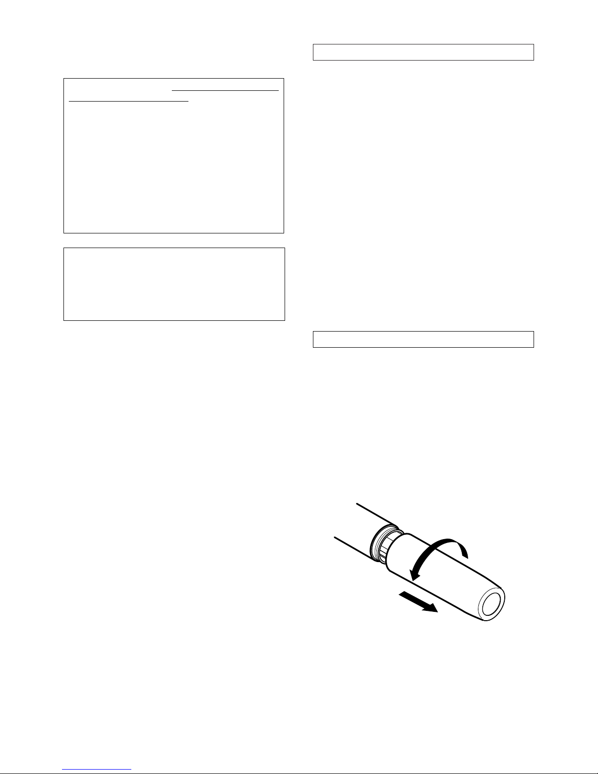
Battery Installation
1. While holding the transmitter body at the on-off
switch, unscrew the lower body cover and slide it off
to expose the battery compartment (Fig. A).
Fig. A
Introduction
3
Transmitter Setup
2
Notice to individuals
with implanted cardiac
pacemakers or AICD devices:
Any source of RF (radio frequency) energy
may
interfere with normal functioning of the implanted
device. All wireless microphones have low-power
transmitters (less than 0.05 watts output) which are
unlikely to cause difficulty, especially if they are at
least a few inches away. Note also that
any medicaldevice disruption will cease when the RF transmitting
source is turned off
. Please contact your physician or
medical-device provider if you have any questions, or
experience any problems with the use of this or any
other RF equipment.
CAUTION! The circuits inside the receiver and
transmitter have been precisely adjusted for
optimum performance and compliance with federal
regulations. Do not attempt to open the receiver or
transmitter. To do so will void the warranty, and may
cause improper operation.
5
Fig. E
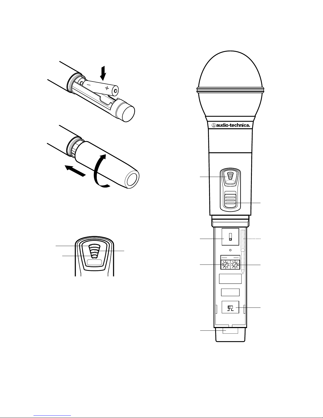
Transmitter Controls
BATT
ON
RF POWER
HL
PAD (
dB)
–
6
0
–12
CH
Battery
Condition
Indicator
Pad
Switch
Channel
Switch
x10
Power
Switch
Channel
Switch
x1
RF
Power/
BatterySave
Switch
Screwdriver
Storage
Control explanations on page 6.
Serial
Number
2.
Observe correct polarity as marked inside the bat-
tery compartment
and carefully insert two fresh 1.5V
AA alkaline batteries (Fig. B). Because there is some
variation in actual battery dimensions, make
certain the batteries are
fully
seated in the battery
compartment.
3. Replace the lower body cover (Fig. C).
Do not
overtighten.
Battery Condition Indicator
After the batteries are installed, turn the power on. The
red battery condition indicator LED (Fig. D) should flash
momentarily and the green indicator should come on. If
this does not happen, the batteries are installed incorrectly or they are dead. If the yellow or red indicator
stays on, the battery voltage is low and the batteries
should be replaced. If this happens during use, replace
the batteries immediately to ensure continued operation.
4
Fig. B
Fig. C
Fig. D
BATT
Green
Red
Yellow
 Loading...