

Page 1

ESW-T212
UHF Plug-on Transmitter
Installation and Operation
Page 2
3
Battery Condition Indicator
After the battery is installed, turn the power on. The
battery condition indicator LED (Fig. C, page 4) should
flash momentarily. If it does not, the battery is installed
incorrectly or it is dead.
If the indicator LED stays on (does not flash), the
battery voltage is low and the battery should be
replaced. If this happens during use, replace the
battery immediately to ensure continued operation.
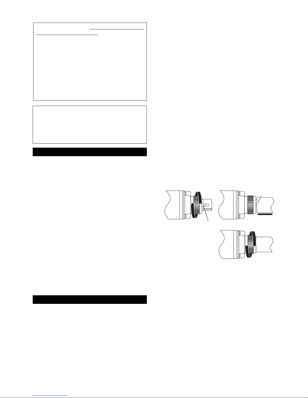
Transmitter Input Connection
The ESW-T212 transmitter has a 3-pin XLRF-type input
connector with a locking collar. Use a dynamic
microphone, or a condenser mic with an internal
battery. To attach the microphone, rotate the threaded
locking collar
fully
clockwise (“down”) until it reaches
the transmitter housing (Fig. B1). Then rotate the collar
back “up” one or two turns to expose the microphone
latch.
Press the microphone and transmitter together (Fig.
B2), making certain that the latch “clicks” into the base
of the mic. Pull on the mic to make certain it is latched
on the connector.
Continue to rotate the threaded collar “up” until it is
firmly
against the end of the mic (Fig. B3). Make
certain the mic is securely attached before use.
To detach the microphone, reverse the steps above.
Always
loosen the threaded collar
fully
before
attempting to disconnect the mic.
The ESW-T212 provides a bias voltage of +5V on Pins
2 and 3 which will power some “battery/phantom”
mics designed to work at this low voltage. However,
the ESW-T212 will not power a “phantom powered”
mic which requires the more-typical 12 to 48 volts. Use
of the bias voltage will reduce battery life slightly.
Presence of the bias voltage will not affect dynamic
microphones.
Pin 1 Case Ground
Pin 2 Audio “+” and 5V DC bias
Pin 3 Audio “–” and 5V DC bias
Transmitting Antenna
The ESW-T212’s plug-on transmitter’s antenna is
housed in a non-metallic section between the metal
transmitter case and the mic connector. For best operation, hold the body of the microphone itself and do not
cover or obstruct the antenna area.
Fig. B
B1
B2
B3
Latch
“CLICK”
2
Notice to individuals
with implanted cardiac
pacemakers or AICD devices:
Any source of RF (radio frequency) energy
may
interfere with normal functioning of the implanted
device. All wireless microphones have low-power
transmitters (less than 0.05 watts output) which are
unlikely to cause difficulty, especially if they are at
least a few inches away. Note also that
any medicaldevice disruption will cease when the RF transmitting
source is turned off
. Please contact your physician or
medical-device provider if you have any questions, or
experience any problems with the use of this or any
other RF equipment.
CAUTION! The circuits inside the receiver and
transmitter have been precisely adjusted for
optimum performance and compliance with federal
regulations. Do not attempt to open the receiver or
transmitter. To do so will void the warranty, and may
cause improper operation.
Audio-Technica Engineered Sound
®
wireless systems
are offered as separate receiver and transmitter units,
rather than in predetermined combinations, for greatest
system flexibility. Operating details for Engineered
Sound receivers and overall system operation are
included with each receiver.
Engineered Sound receivers feature a sophisticated
Tone Lock
™
tone squelch system that opens only when
an Engineered Sound transmitter is detected, reducing
the possibility of interference. As a result, Engineered
Sound transmitters and receivers must be used
together and should not be used with components
from other Audio-Technica wireless systems, or with
those of other manufacturers.
Please note that in multiple-system applications there
must be a transmitter-receiver pair set to a separate
frequency for each input desired (only one transmitter
at a time for each receiver). Because the wireless
frequencies are on UHF TV frequencies, only certain
wireless frequencies may be useable in a particular
geographic area. Also, only certain of the available
operating frequencies may be used together.
(Suggestions for multiple-system frequency grouping
will be found on pages 6-7.)
Battery Selection and Installation
Always use a fresh alkaline 9V battery. Turn the Power
switch “Off” before inserting a battery.
Open the hinged battery door. Insert the battery,
observing correct polarity as marked inside the battery
compartment. Close the battery door.
Do not force the
door closed.
Introduction
Transmitter Setup
Page 3

5
Setting Levels
Although Engineered Sound receivers require no level
adjustment, correct adjustment of transmitter audio
input and mixer/amplifier input and output levels is
important for optimum system performance.
Setting Mic Level
CAUTION! Adjust the Mic Level control
carefully
.
Unlike the Channel Selector switches, it will
not
rotate
continuously!
1. Plug in the microphone and power up the system.
2. Set the Mic Level control to the full clockwise (Hi)
position. Speak/sing into the microphone at typicallyloud levels while watching the AF Level indicators on
the receiver. Maximum audio input to the mic should
light about three or four green LEDs. Audio modulation from the transmitter level should not be allowed
to light the red LED – doing so will cause the system
to overload and distort.
RF Interference
Please note that wireless frequencies are shared with
other radio services. According to Federal
Communications Commission regulations, “Wireless
microphone operations are unprotected from interference from other licensed operations in the band. If any
interference is received by any Government or nonGovernment operation, the wireless microphone must
cease operation...”
If you need assistance with operation or frequency
selection, please contact your dealer or the
Audio-Technica professional division. Extensive wireless
information also is available on the Audio-Technica Web
site at www.audio-technica.com.
Specifications
†
OVERALL SYSTEM
Operating Frequency UHF band, 728.125 to
740.500 MHz
Number of Channels 100 total
Frequency Stability ±0.005%, Phase Lock Loop
frequency control
Modulation Mode FM
Normal Deviation ±5 kHz
Tone Squelch Frequency 32.768 kHz
Operating Range 300' typical
Operating Temperature Range 41° F (5° C) to 113° F (45° C)
Frequency Response 100 Hz to 15 kHz
ESW-T212 PLUG-ON TRANSMITTER
RF Power Output 10 mW typical
Spurious Emissions Under federal regulations
Input Connectors 3-pin XLRF-type
Battery 9V (NEDA type 1604) alkaline,
not included
Current Consumption 60 mA typical
Battery Life Approximately 7-9 hours
(depending on battery type
and use pattern)
Dimensions 1.58" (40.0 mm) W
x 4.32" (109.8 mm) H
x 1.58" (40.0 mm) D
Net Weight (without battery) 6.2 oz (177 grams)
† In the interest of standards development, A.T.U.S. offers full details on its test
methods to other industry professionals on request.
Turn down the mixer/amplifier level before starting
up the wireless system.
Switch on the receiver. Do
not
switch on the
transmitter yet.
Receiver On…
The Channel Designator Display will light. If any of the
RF LEDs light up at this point, there may be RF
interference in the area. If this occurs, select another
frequency using the front-panel channel selectors.
While holding in the “Set” button, press the “Up” or
“Down” button to access the desired frequency; then
release the Set button to select the channel.
Transmitter On…
Before turning on the transmitter, use the provided
screwdriver to set the transmitter channel selector
switches (Fig. C) to the same numbers as those displayed on the receiver. Always turn the transmitter off
when changing frequencies. When the transmitter is
switched on and in normal operation, the receiver’s RF
signal level indicators will light up from left to right. For
optimum performance at least four, and preferably five,
of the signal strength indicators should light up when
the transmitter is switched on. One of the Tuner LEDs
(A or B) also will light up when the transmitter is on,
indicating that its signal has been received and the
receiver’s Tone Lock squelch circuit has opened.
System Operation
4
Transmitter Controls
POWER SWITCH: The Power switch controls the entire
transmitter. There is about a half-second delay after the
transmitter is switched to the “On” position before the
receiver’s Tone Lock squelch un-mutes.
Input
Connector
Power Switch
(On/Standby/Off)
Battery Condition
Indicator
Microphone
Level Control
Channel Selector
Switches
CHANNEL SWITCHES: The left channel selector switch
corresponds to the receiver‘s left-column channel
display number (tens); the right switch corresponds to
the receiver‘s right-column channel display number
(units). Always turn the transmitter off when changing
frequencies.
MICROPHONE LEVEL CONTROL: This control permits
the ESW-T212 to accommodate a wide range of mics
with typical sensitivity ratings of 1.5 mV (-56 dB) to 15
mV (-36 dB) at 1 Pascal/94 dB SPL, while providing
excellent signal-to-noise ratios and maximum acousticinput levels.
Fig. C
ON
Lo Hi
BATT
OFF
STAND BY
0
9
8
7
6
5
X
10
1
4
CHANNELMIC LEVEL
2
3
ESW-T212
0
9
1
2
8
3
7
4
6
5
X
1
Page 4

6
Multi-channel Systems
Following are groupings of frequencies suggested for
multi-channel wireless systems.
Group A: Channels 00, 02, 08, 15, 46, 50, 60 (or 62),
71, 76, 80, 93, 99
-or-
Group B: Channels 01, 03, 07, 25, 30, 41, 44, 56, 69,
76, 77, 86
For use where TV Channel 57 is operating:
Channels 50, 60 (or 62), 71, 76, 80, 93, 99
(from Group A)
-or-
Channels 56, 69, 76, 77, 86 (from Group B)
Frequency and Channel Designator List
Designator Frequency (MHz) TV Channel
00 728.125 57
01 728.250 57
02 728.375 57
03 728.500 57
04 728.625 57
05 728.750 57
06 728.875 57
07 729.000 57
08 729.125 57
09 729.250 57
10 729.375 57
11 729.500 57
12 729.625 57
13 729.750 57
14 729.875 57
15 730.000 57
16 730.125 57
17 730.250 57
18 730.375 57
19 730.500 57
20 730.625 57
21 730.750 57
22 730.875 57
23 731.000 57
24 731.125 57
25 731.250 57
26 731.375 57
27 731.500 57
28 731.625 57
29 731.750 57
30 731.875 57
31 732.000 57
32 732.125 57
33 732.250 57
34 732.375 57
35 732.500 57
36 732.625 57
37 732.750 57
38 732.875 57
39 733.000 57
40 733.125 57
41 733.250 57
42 733.375 57
43 733.500 57
44 733.625 57
45 733.750 57
46 733.875 57
47 734.000 58
48 734.125 58
49 734.250 58
Engineered Sound®UHF Wireless
7
Operating Frequencies
Designator Frequency (MHz) TV Channel
50 734.375 58
51 734.500 58
52 734.625 58
53 734.750 58
54 734.875 58
55 735.000 58
56 735.125 58
57 735.250 58
58 735.375 58
59 735.500 58
60 735.625 58
61 735.750 58
62 735.875 58
63 736.000 58
64 736.125 58
65 736.250 58
66 736.375 58
67 736.500 58
68 736.625 58
69 736.750 58
70 736.875 58
71 737.000 58
72 737.125 58
73 737.250 58
74 737.375 58
75 737.500 58
76 737.625 58
77 737.750 58
78 737.875 58
79 738.000 58
80 738.125 58
81 738.250 58
82 738.375 58
83 738.500 58
84 738.625 58
85 738.750 58
86 738.875 58
87 739.000 58
88 739.125 58
89 739.250 58
90 739.375 58
91 739.500 58
92 739.625 58
93 739.750 58
94 739.875 58
95 740.000 59
96 740.125 59
97 740.250 59
98 740.375 59
99 740.500 59
For use where TV Channel 58 is operating:
Channels 00, 02, 08, 15, 46, 99 (from Group A)
-or-
Channels 01, 03, 07, 25, 30, 41, 44 (from Group B)
For use where TV Channel 59 is operating:
Channels 00, 02, 08, 15, 46, 50, 60 (or 62), 71, 76,
80, 93 (from Group A)
-or-
Channels 01, 03, 07, 25, 30, 41, 44, 56, 69, 76, 77,
86 (All of Group B)
Page 5

Audio-Technica U.S., Inc., 1221 Commerce Drive,
Stow, Ohio 44224 330/ 686-2600
www.audio-technica.com
P51481-B/W ©2002 Audio-Technica U.S., Inc. Printed in U.S.A.
One-Year Limited Warranty
Audio-Technica professional wireless systems purchased in the U.S.A.
are warranted for one year from date of purchase by Audio-Technica
U.S., Inc. ( A.T.U.S.) to be free of defects in materials and workmanship.
In event of such defect, product will be repaired promptly without
charge or, at our option, replaced with a new product of equal or
superior value if delivered to A.T.U.S. or an Authorized Service Center,
prepaid, together with the sales slip or other proof of purchase date.
Prior approval from A.T.U.S. is required for return.
This warranty
excludes defects due to normal wear, abuse, shipping damage, or
failure to use product in accordance with the instructions. This
warranty is void in the event of unauthorized repair or modification, or
removal or defacing of the product labeling.
For return approval and shipping information,
contact the Service
Dept., Audio-Technica U.S., Inc., 1221 Commerce Drive, Stow, Ohio
44224.
Except to the extent precluded by applicable state law,
A.T.U.S. will
have no liability for any consequential, incidental, or special
damages; any warranty of merchantability or fitness for
particular purpose expires when this warranty expires.
This warranty gives you specific legal rights, and you may have other
rights which vary from state to state.
Outside the U.S.A., please contact your local dealer for warranty
details.
For future reference, please record your system
information here (the serial number appears inside
the battery compartment):
Transmitter ESW-T212
Serial Number
Tips To Obtain The Best Results
• Use only fresh alkaline batteries. Do not use
“general purpose” (carbon-zinc) batteries.
• The transmitter and the receiver should be as
close together as conveniently possible, but
no closer together than three feet. Maintain
line-of-sight between them whenever
possible.
• Each transmitter/receiver pair must be set to
the same channel number.
• A single receiver cannot receive signals from
two transmitters at the same time.
• You need to change channels 1) when a
strong interference signal is received, 2) when
the channel breaks down, or 3) during
multiple-system operation in order to select an
interference-free channel.
• Turn the transmitter off when not in use.
Remove the battery if the transmitter is not
to be used for a period of time.
 Loading...