

Page 1

ESW-T211
UHF UniPak™Transmitter
Installation and Operation
Page 2
Audio-Technica Engineered Sound®wireless systems
are offered as separate receiver and transmitter units,
rather than in predetermined combinations, for greatest
system flexibility. Operating details for Engineered
Sound receivers and overall system operation are
included with each receiver.
Engineered Sound receivers feature a sophisticated
Tone Lock
™
tone squelch system that opens only when
an Engineered Sound transmitter is detected, reducing
the possibility of interference. As a result, Engineered
Sound transmitters and receivers must be used
together and should not be used with components
from other Audio-Technica wireless systems, or with
those of other manufacturers.
Please note that in multiple-system applications there
must be a transmitter-receiver pair set to a separate
frequency for each input desired (only one transmitter
at a time for each receiver). Because the wireless
frequencies are on UHF TV frequencies, only certain
wireless frequencies may be useable in a particular
geographic area. Also, only certain of the available
operating frequencies may be used together.
(Suggestions for multiple-system frequency grouping
will be found on pages 10-11.)
Battery Selection and Installation
The transmitter uses two 1.5V AA batteries, not
included. Alkaline type is recommended. Always
replace both batteries.
Make certain the transmitter
power switch is turned Off before replacing
batteries.
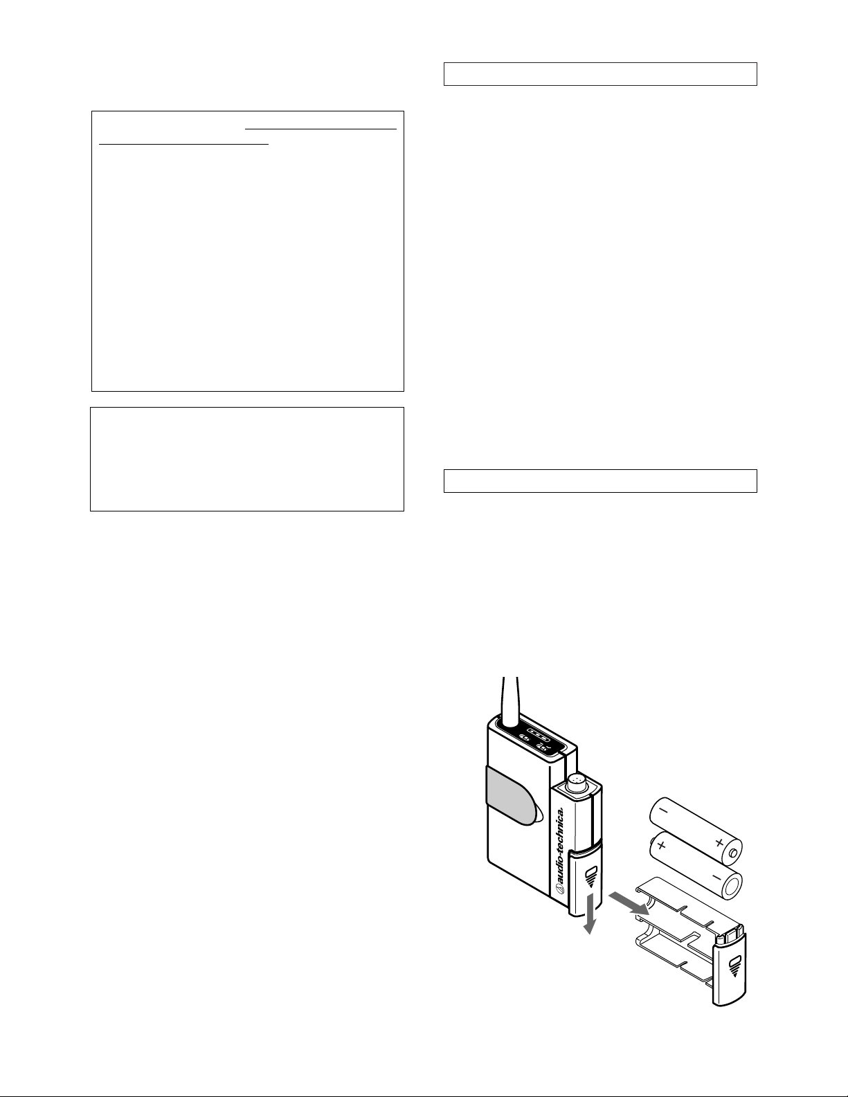
Battery Installation
1. Slide down the battery latching cover and pull out
the battery drawer as shown in Figure A. (A screwdriver for adjusting operating frequency is stored on the
back of the drawer.)
Fig. A
Introduction
3
BATT
OFF
ON
PWR
OPEN
OPEN
Transmitter Setup
2
Notice to individuals
with implanted cardiac
pacemakers or AICD devices:
Any source of RF (radio frequency) energy
may
interfere with normal functioning of the implanted
device. All wireless microphones have low-power
transmitters (less than 0.05 watts output) which are
unlikely to cause difficulty, especially if they are at
least a few inches away. However, since a
“body-pack” mic transmitter typically is placed against
the body, we suggest attaching it at the belt, rather than
in a shirt pocket where it may be immediately adjacent
to the medical device. Note also that
any medicaldevice disruption will cease when the RF transmitting
source is turned off
. Please contact your physician or
medical-device provider if you have any questions, or
experience any problems with the use of this or any
other RF equipment.
CAUTION! The circuits inside the receiver and
transmitter have been precisely adjusted for
optimum performance and compliance with federal
regulations. Do not attempt to open the receiver or
transmitter. To do so will void the warranty, and may
cause improper operation.
Page 3
5
Fig. C
Setup Control Panel
1
4
5
6
2
3
1
4
5
6
2
3
CH
GT
MT
LoHiLo
Hi
Hi
Lo
RF
POWER
(Refer to Fig. C, Setup Control Panel)
INPUT TRIMMERS: These controls permit adjustment
of Mic Level (MT) and Guitar Level (GT) to match a
wide range of input devices, as described in a following
section. The trimmer
not
in use should be set to
minimum.
CHANNEL SWITCHES: The left channel selector switch
corresponds to the receiver‘s left-column channel
display number (tens); the right switch corresponds to
the receiver‘s right-column channel display number
(units). Always turn the transmitter off when changing
frequencies.
RF POWER / BATTERY-SAVE SWITCH: As supplied, the
switch is set in the “Hi” position for maximum range.
Switching to the “Lo” position increases battery life
somewhat by reducing power. (Note: Effective range
may decrease when the switch is set at the Lo
position.)
RF
Power/
Battery-
Save
Switch
x10 x1
Channel
Switches
Input Level
Guitar Mic
2.
Observe correct polarity as marked inside the bat-
tery compartment
and carefully insert two fresh 1.5V
AA alkaline batteries. Because there is some
variation in actual battery dimensions, make certain the
batteries are
fully
seated in the battery compartment.
3. Carefully insert the battery drawer fully,
but do not
force the drawer in
. Then slide the cover up to latch
the drawer.
Battery Condition Indicator
After the batteries are installed, turn the power on. The
red battery condition indicator LED on the user control
panel should flash momentarily and the green indicator
should come on. If this does not happen, the batteries
are installed incorrectly or they are dead. If the yellow
or red indicator stays on, the battery voltage is low and
the batteries should be replaced. If this happens during
use, replace the batteries immediately to ensure
continued operation.
Transmitter Input Connection
Connect an audio input device (microphone or guitar
cable) to the audio input connector beside the user
control panel (Fig. B).
A number of Audio-Technica professional microphones
and cables are available separately, pre-terminated with
a UniPak
™
input connector (see “Transmitter
Accessories” on page 9).
Transmitter Controls
(Refer to Fig. B, User Control Panel)
POWER SWITCH: The Power switch controls the entire
transmitter. Its handle is designed to be felt and
activated easily even through clothing or other
garments. There is about a half-second delay after
transmitter turn-on before the receiver’s Tone Lock
squelch un-mutes.
HIGH-PASS SWITCH: The ESW-T211 offers an audio
high-pass switch which reduces low frequencies, when
desired. It affects only the microphone input and is
recessed to avoid accidental activation. Use this switch
to reduce pickup of low-frequency noise caused by
clothing and/or user movement.
4
High-pass
Switch
BATT
OFF
ON
PWR
Fig. B
User Control Panel
Power
Switch
Audio Input
Connector
Battery
Condition
Indicator
Page 4

Turn down the mixer/amplifier level before starting
up the wireless system.
Switch on the receiver. Do
not
switch on the
transmitter yet.
Receiver On…
The Channel Designator Display will light. If any of the
RF LEDs light up at this point, there may be RF
interference in the area. If this occurs, select another
frequency using the front-panel channel selectors.
While holding in the “Set” button, press the “Up” or
“Down” button to access the desired frequency; then
release the Set button to select the channel.
Transmitter On…
Before turning on the transmitter, use the provided
screwdriver to set the transmitter channel selector
switches (Fig. C) to the same numbers as those displayed on the receiver. Always turn the transmitter off
when changing frequencies. When the transmitter is
switched on and in normal operation, the receiver’s RF
signal level indicators will light up from left to right. For
optimum performance at least four, and preferably five,
of the signal strength indicators should light up when
the transmitter is switched on. One of the Tuner LEDs
(A or B) also will light up when the transmitter is on,
indicating that its signal has been received and the
receiver’s Tone Lock squelch circuit has opened.
Setting Levels
Although Engineered Sound receivers require no level
adjustment, correct adjustment of transmitter audio
input and mixer/amplifier input and output levels is
important for optimum system performance.
Transmitter Input Levels
Input trimmer controls in the UniPak transmitter (Fig. C)
will enable you to use microphones or instruments with
different output levels.
1. Set both the transmitter Mic Level (MT) and Guitar
Level (GT) controls to their full counter-clockwise
position (minimum). (The level control not being used
should always be set to minimum.)
2. Plug the mic or instrument into the transmitter and
power up the system.
3.
For MIC:
Make an initial adjustment of the mixer’s
level controls that will allow audio through the system
as you increase the transmitter’s Mic Level.
For INSTRUMENT:
Make an initial adjustment of
the instrument amplifier input level control that will
allow audio through the system as you increase the
transmitter’s Guitar Level.
4.
For MIC:
While speaking/singing into the microphone at typically-loud levels, turn up the transmitter’s
Mic Level (MT) control until the maximum audio output
of the mic lights about three or four green LED segments on the receiver’s AF Level indicator.
For INSTRUMENT:
While playing the instrument at
typically-loud levels, turn up the transmitter’s Guitar
Level (GT) control until the maximum audio output of
the instrument lights about three or four green LED
segments on the receiver’s AF Level indicator.
7
System Operation
6
Do
Not
Remove
Fig. D
Transmitter Antenna
The ESW-T211 features a field-replaceable antenna, in
the unlikely event that it becomes damaged. Use only
an original Audio-Technica replacement part, available
from the Audio-Technica service department.
1. Referring to Figure E, fully unscrew only screw “A”
and remove it. Do
not
remove the other case screw.
2. Pull the broken antenna straight out of the transmitter case, without twisting it.
3.
Carefully
insert the replacement antenna, without
twisting it, and without damaging the PC board trace.
Look in the open hole “A” to assure that the antenna is
fully seated.
4. Reinstall screw “A,” tightening only until it is snug.
Fig. E
Screw “A”
Mounting Clips
The ESW-T211 is supplied with two mounting clips for
attachment to different types/shapes of objects.
Attach the clips by springing their ends into the two
holes on the sides of the transmitter case (Fig. D). The
clips may be installed with the case positioned either
“up” or “down,” depending upon which is preferred
for the application.
Page 5

9
Specifications
†
OVERALL SYSTEM
Operating Frequency UHF band, 728.125 to
740.500 MHz
Number of Channels 100 total
Frequency Stability ±0.005%, Phase Lock Loop
frequency control
Modulation Mode FM
Normal Deviation ±5 kHz
Tone Squelch Frequency 32.768 kHz
Operating Range 300' typical
Operating Temperature Range 41° F (5° C) to 113° F (45° C)
Frequency Response 100 Hz to 15 kHz
ESW-T211 UNIPAK™TRANSMITTER
RF Power Output 50 mW Max
(Hi: 10 mW; Lo: 5 mW, typical)
Spurious Emissions Under federal regulations
Input Connections High impedance, low impedance,
bias
Bias Voltage 5V, 5 mA Max
High-pass (low-freq. roll-off) 150 Hz, 6 dB per octave
(mic input only)
Batteries Two 1.5V AA type alkaline,
not included
Current Consumption Hi: 130 mA; Lo: 120 mA, typical
Battery Life Hi: 12 hours; Lo: 14 hours,
typical (depending on battery
type and use pattern)
Dimensions 2.56" (65.0 mm) W x 6.57"
(167.0 mm) H x 1.02"
(26.0 mm) D
Net Weight (without batteries) 2.7 oz (75 grams)
Accessory Included Alternate mounting clip
† In the interest of standards development, A.T.U.S. offers full details on its test
methods to other industry professionals on request.
Transmitter Accessories
(All are terminated for use with the ESW-T211 UniPak transmitter.)
AT829cW AT829 miniature cardioid condenser microphone only.
Includes clothing clip and windscreen.
MT830cW MT830R subminiature omnidirectional condenser
microphone only. Includes clothing clip and
windscreen.
MT830cW-TH ”Theater“ model, same as MT830cW except beige
color mic and cable for concealment.
AT831cW AT831b miniature cardioid condenser microphone
only. Includes clothing clip and windscreen.
AT851cW AT851a surface-mount wide-range hemi-cardioid
condenser microphone only.
AT857AMLcW AT857AMLa 19" gooseneck cardioid microphone only.
Mounts to 5/8"-27 thread. Includes windscreen.
AT889cW Headworn noise-canceling condenser microphone
only. Includes windscreen and cable clip.
ATM35cW ATM35 high-intensity miniature cardioid condenser
microphone only. Includes AT8418 clip-on instrument
mount.
ATM73cW ATM73a headworn cardioid condenser microphone
only.
ATM75cW ATM75 headworn cardioid condenser microphone
only. Includes windscreens and cable clip.
PRO 8HEcW PRO 8HEx headworn hypercardioid dynamic
microphone. Includes windscreen and cable clip.
PRO 35xcW PRO 35x cardioid condenser microphone only.
Includes AT8418 clip-on instrument mount.
AT-GCW Hi-Z instrument/guitar cable with 1/4" phone plug.
XLRW Connecting cable for UniPak transmitter with an
XLRF-type input connector, for Lo-Z microphones with
XLRM-type output terminations.
8
NOTE: Do not set the transmitter level too high (as
indicated by lighting of the red LED) – doing so will
cause the system to overload and distort.
5.
For MIC:
Next, while again speaking/singing into the
microphone at typically-loud levels, adjust the mixer’s
input trim control so the highest sound pressure level
going into the microphone causes no input overload in
the mixer, and yet permits the mixer’s channel and
output level controls to operate in their “normal” range
(not set too high or too low).
For INSTRUMENT:
Next, while again playing the
instrument at typically-loud levels, adjust the amplifier’s
input control so the highest signal level causes no
overload in the instrument amplifier.
CAUTION! The small trimmer controls are delicate; use
only a small screwdriver or alignment tool with a
maximum
3
/32"-wide blade. Do not force the trimmers
beyond their normal 260° range of rotation.
RF Interference
Please note that wireless frequencies are shared with
other radio services. According to Federal
Communications Commission regulations, “Wireless
microphone operations are unprotected from interference from other licensed operations in the band. If any
interference is received by any Government or nonGovernment operation, the wireless microphone must
cease operation...”
If you need assistance with operation or frequency
selection, please contact your dealer or the
Audio-Technica professional division. Extensive wireless
information also is available on the Audio-Technica Web
site at www.audio-technica.com.
Tips To Obtain The Best Results
• Use only fresh alkaline batteries. Do not use
“general purpose” (carbon-zinc) batteries.
• The transmitter and the receiver should be as
close together as conveniently possible, but
no closer together than three feet. Maintain
line-of-sight between them whenever
possible.
• Each transmitter/receiver pair must be set to
the same channel number.
• A single receiver cannot receive signals from
two transmitters at the same time.
• You need to change channels 1) when a
strong interference signal is received, 2) when
the channel breaks down, or 3) during
multiple-system operation in order to select an
interference-free channel.
• The “MT” or “GT” input control not in use
should be set to minimum.
• Turn the transmitter off when not in use.
Remove the batteries if the transmitter is not
to be used for a period of time.
Page 6

11
Designator Frequency (MHz) TV Channel
50 734.375 58
51 734.500 58
52 734.625 58
53 734.750 58
54 734.875 58
55 735.000 58
56 735.125 58
57 735.250 58
58 735.375 58
59 735.500 58
60 735.625 58
61 735.750 58
62 735.875 58
63 736.000 58
64 736.125 58
65 736.250 58
66 736.375 58
67 736.500 58
68 736.625 58
69 736.750 58
70 736.875 58
71 737.000 58
72 737.125 58
73 737.250 58
74 737.375 58
75 737.500 58
76 737.625 58
77 737.750 58
78 737.875 58
79 738.000 58
80 738.125 58
81 738.250 58
82 738.375 58
83 738.500 58
84 738.625 58
85 738.750 58
86 738.875 58
87 739.000 58
88 739.125 58
89 739.250 58
90 739.375 58
91 739.500 58
92 739.625 58
93 739.750 58
94 739.875 58
95 740.000 59
96 740.125 59
97 740.250 59
98 740.375 59
99 740.500 59
For use where TV Channel 58 is operating:
Channels 00, 02, 08, 15, 46, 99 (from Group A)
-or-
Channels 01, 03, 07, 25, 30, 41, 44 (from Group B)
For use where TV Channel 59 is operating:
Channels 00, 02, 08, 15, 46, 50, 60 (or 62), 71, 76,
80, 93 (from Group A)
-or-
Channels 01, 03, 07, 25, 30, 41, 44, 56, 69, 76, 77,
86 (All of Group B)
10
Multi-channel Systems
Following are groupings of frequencies suggested for
multi-channel wireless systems.
Group A: Channels 00, 02, 08, 15, 46, 50, 60 (or 62),
71, 76, 80, 93, 99
-or-
Group B: Channels 01, 03, 07, 25, 30, 41, 44, 56, 69,
76, 77, 86
For use where TV Channel 57 is operating:
Channels 50, 60 (or 62), 71, 76, 80, 93, 99
(from Group A)
-or-
Channels 56, 69, 76, 77, 86 (from Group B)
Frequency and Channel Designator List
Designator Frequency (MHz) TV Channel
00 728.125 57
01 728.250 57
02 728.375 57
03 728.500 57
04 728.625 57
05 728.750 57
06 728.875 57
07 729.000 57
08 729.125 57
09 729.250 57
10 729.375 57
11 729.500 57
12 729.625 57
13 729.750 57
14 729.875 57
15 730.000 57
16 730.125 57
17 730.250 57
18 730.375 57
19 730.500 57
20 730.625 57
21 730.750 57
22 730.875 57
23 731.000 57
24 731.125 57
25 731.250 57
26 731.375 57
27 731.500 57
28 731.625 57
29 731.750 57
30 731.875 57
31 732.000 57
32 732.125 57
33 732.250 57
34 732.375 57
35 732.500 57
36 732.625 57
37 732.750 57
38 732.875 57
39 733.000 57
40 733.125 57
41 733.250 57
42 733.375 57
43 733.500 57
44 733.625 57
45 733.750 57
46 733.875 57
47 734.000 58
48 734.125 58
49 734.250 58
Engineered Sound®UHF Wireless Operating Frequencies
Page 7

Audio-Technica U.S., Inc., 1221 Commerce Drive,
Stow, Ohio 44224 330/ 686-2600
www.audio-technica.com
P#2323-02490 P51249-B/ W ©2000 Audio -Technica U.S., Inc.
Printed in Japan
One-Year Limited Warranty
Audio-Technica professional wireless systems purchased in the U.S.A.
are warranted for one year from date of purchase by Audio-Technica
U.S., Inc. ( A.T.U.S.) to be free of defects in materials and workmanship.
In event of such defect, product will be repaired promptly without
charge or, at our option, replaced with a new product of equal or
superior value if delivered to A.T.U.S. or an Authorized Service Center,
prepaid, together with the sales slip or other proof of purchase date.
Prior approval from A.T.U.S. is required for return.
This warranty
excludes defects due to normal wear, abuse, shipping damage, or
failure to use product in accordance with the instructions. This
warranty is void in the event of unauthorized repair or modification, or
removal or defacing of the product labeling.
For return approval and shipping information,
contact the Service
Dept., Audio-Technica U.S., Inc., 1221 Commerce Drive, Stow, Ohio
44224.
Except to the extent precluded by applicable state law,
A.T.U.S. will
have no liability for any consequential, incidental, or special
damages; any warranty of merchantability or fitness for
particular purpose expires when this warranty expires.
This warranty gives you specific legal rights, and you may have other
rights which vary from state to state.
Outside the U.S.A., please contact your local dealer for warranty
details.
For future reference, please record your system
information here (the serial number appears inside
the battery compartment):
Transmitter ESW-T211
Serial Number
 Loading...