

Audio Technica ESW-R220 Installation And Operation Manual

UHF Wireless Systems
ESW-R220
UHF Synthesized Diversity Dual Receiver
Installation and Operation
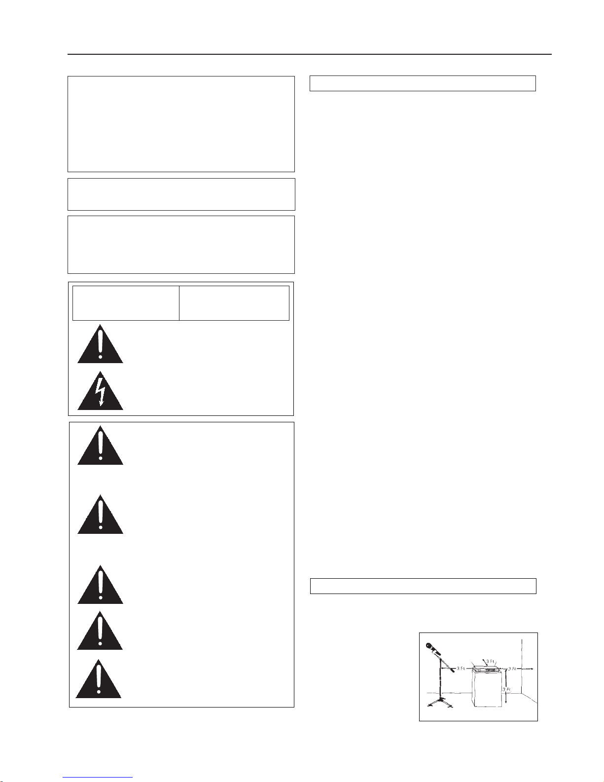
Location
For best operation the receiver should be at least 3 ft.
above the ground and at least 3 ft. away from a wall or
metal surface to minimize
reflections. The transmitter
should be at least 3 ft. from
the receiver, as shown in
Figure A.
Keep antennas away from
noise sources such as digital
equipment, motors,
automobiles and neon
lights, as well as large
metal objects.
2
ESW-R220 UHF Synthesized Diversity Dual Receiver
Installation and Operation
CAUTION! The circuits inside the receiver and transmitter
have been precisely adjusted for optimum performance and
compliance with federal regulations. Do not attempt to open
the receiver or transmitter. To do so will void the warranty, and
may cause improper operation.
Individuals with implanted cardiac pacemakers or AICD
devices: Please see notice on back cover.
This device complies with part 15 of the FCC Rules. Operation
is subject to the condition that this device does not cause
harmful interference.
This device complies with INDUSTRY CANADA R.S.S. 210, en
conformité avec IC: RSS-210/CNR210. Operation is subject to
the following conditions: 1) This device may not cause harmful
interference and 2) this device must accept any interference
received, including interference which may cause undesired
operation.
Introduction
Audio-Technica Engineered Sound®wireless systems are
offered as separate receiver and transmitter units, rather
than in predetermined combinations, for greatest system
flexibility. Operating details for Engineered Sound transmitters are included with each transmitter.
Engineered Sound receivers feature a sophisticated Tone
Lock
™
tone squelch system that opens only when an
Engineered Sound transmitter is detected, reducing the
possibility of interference. As a result, Engineered Sound
transmitters and receivers must be used together and
should not be used with components from other
Audio-Technica wireless systems, or with those of other
manufacturers.
The ESW-220 Dual Receiver unit features two independent
receivers in its housing, along with an antenna combiner/
divider system. Each receiver offers 100 PLL-synthesized
UHF frequencies and true diversity reception. In each
receiver, two antennas feed two completely independent
RF sections (Tuners) on the same frequency. Automatic
logic circuitry continuously compares and selects the superior received signal, providing better sound quality and
reducing the possibility of interference and dropouts. The
ESW-R220 is housed in a full-width standard 19" (1U)
rack-mountable case, with rack-mount adapters included.
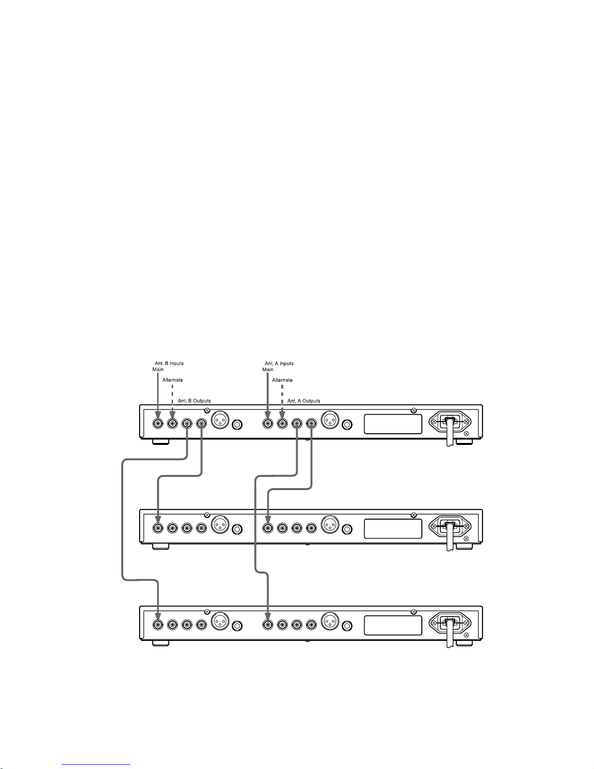
The antenna combiner/divider system in the ESW-R220
provides two “A” and two “B” antenna inputs that feed
each of the two diversity tuners in each receiver. As one
example, the two pairs of inputs might be used when
coverage of a split banquet/meeting room is difficult with
a single pair of antennas, or when considerable multipath
interference is present. Two “A“ and two “B“ antenna
output
jacks are provided to feed other wireless receivers
operating in the same frequency band. With the addition of
two more ESW-R220 dual receiver units, up to six receiver
channels can be operated from a single pair of antennas.
However, any type of receiver in the same band, or even a
separate active antenna divider, may be fed by the antenna
outputs. The ESW-R220 also provides +12V DC on the
antenna input jacks to power in-line RF devices.
Please note that in multiple-system applications there must
be a transmitter-receiver pair set to a separate frequency for
each input desired (only one transmitter at a time for each
receiver). Because the wireless frequencies are on UHF TV
frequencies, only certain wireless frequencies may be useable in a particular geographic area. Also, only certain of the
available operating frequencies may be used together in
multi-channel systems. (Suggestions for multiple-frequency
groupings will be found on page 7.)
Fig. A
AVIS
RISQUE DE CHOC ÉLECTRIQUE
NE PAS OUVRIR
CAUTION
RISK OF ELECTRIC SHOCK
DO NOT OPEN
Warning: This apparatus must be grounded.
This product is a safety class 1 product.
There must be an uninterruptible safety earth
ground from the main power source to the
product‘s AC input. Whenever it is likely that
the protection has been impaired, disconnect
the power cord until the ground has been
restored.
Attention: Cet appareil doit être mise à la
terre. Cet appareil est de classe de sûreté 1.
Il doit y avoir un ininterrompable de mise à la
terre de sécurité provenant de la source
principale de courant de l‘appareil de l‘entrée
du courant alternatif. Quand la protection a été
affaiblie, débrancher le fil de courant jusqu‘à la
mise à terre a bien été réétablie.
Warning: To prevent fire or shock hazard, do
not expose this appliance to rain or moisture.
Attention: Pour prévenir feu ou choc
électrique, ne pas exposé l’appareil à la pluie
ou à l’humidité.
Caution/Avis: For continued protection
against fire hazard, replace only with same
type/rating of fuse.
Pour poursuivre la protection contre le feu,
replacez la fusible de même type/cote.
Warning/Attention: There are some sharp
edges inside. To reduce the risk of injury,
do not remove cover.
Bord tranchant à l‘intérieur. Pour réduire le
risque de blessure, ne pas ouvir le couvercle.
To prevent electric shock, do not remove the
cover. There are no user-serviceable parts
inside. Internal adjustments are for qualified
professionals only. Refer all servicing to
qualified service personnel.
Pour prévenir un choc électrique, ne pas ouvrir
le couvercle. Il n’y aucune pièces de rechanges
à l’intérieur. Tout ajustement interne doit être
fait par une personne qualifié seulement.
Référez tout réparation au personnel qualifié.
Receiver Installation
3
Output Connections
There are two audio output jacks on the back for each of
the receivers: balanced (4 mV) and unbalanced (40 mV).
Use shielded audio cable for the connection between the
receiver and the mixer. If the input of the mixer is a
1
/
4
" jack,
connect a cable from the
1
/
4
" unbalanced audio output on
the back of the receiver housing to the mixer. If the input
of the mixer is an XLR-type input, connect a cable from the
balanced XLR-type audio output on the back panel to the
mixer. The two isolated audio outputs permit simultaneous
feeds to both unbalanced and balanced inputs. For example,
both a tape recorder and a mixer can be driven by each
receiver.
Antennas
Attach a pair of UHF antennas to the antenna input jacks;
connect one to the main “Antenna A In” jack and one to the
main “Antenna B In” jack. See Figure B. The antennas are
normally positioned in the shape of a “V” (45° from vertical)
for best reception.
The antennas can be remotely located from the receiver.
However, due to signal loss in cables at UHF frequencies,
use the lowest-loss RF cable type(s) practical for any cable
runs over 25 feet. RG-8 is a good choice. Use only coppershielded cable, not CATV-type foil-shielded wire.
The two pairs of antenna inputs might be used when
coverage of a split banquet/meeting room is difficult with a
single pair of antennas, or in the case of multipath-prone
areas. Simply connect another set of
remote
antennas to
the alternate “A” and “B” inputs. (Main and alternate
antenna inputs are identical and interchangeable.) The
unique RF nature of each venue normally requires some
experimentation to determine the best locations, if any,
for additional antennas.
All four antenna input jacks also provide +12V DC output
on their center pins to power in-line RF devices. A combined
total of 20 mA can be drawn from the “A” jacks and 20 mA
from the “B” jacks. While an accidental short-circuit will not
harm the internal 12V supply, make certain that an antenna
cable shield does not contact the center conductor.
Power Connections
The switching power supply is designed to operate properly
from any AC power source 120-240V, 50/60 Hz without
adjustment. Simply connect to a standard AC power outlet,
using an IEC input cordset approved for the country of
operation. Use the included cable clamp to secure the plug
in the chassis connector. Power to the unit is controlled by
the front-panel Power switch.
Headphone Jack
A headphone jack on the front panel provides monitoring
of each receiver’s output. The
1
/
4
" TRS jack is intended for
use with stereo headphones. The “Phones” level control
affects the headphone jack only.
Fig. B Antenna Connections
 Loading...