


Audio-Technica ESRSC Specifications
ESRSC
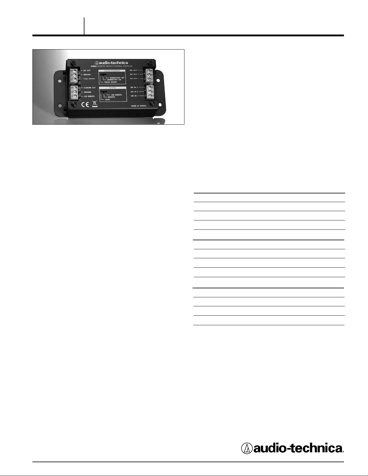
Remote Switch Control Interface
For applications that require a microphone to remain active or
always “on”, regardless of the touch switch setting, a “Local/
Remote/LED Remote” control function is provided.
• When the switch marked “CONTROL” is in the “Local” position,
the user-supplied switch controls the microphone’s audio output,
LED status and contact closure internally.
• When the “CONTROL” switch is in the “Remote” position, t he
microphone’s audio output remains active or “on” all the time. The
user-supplied switch controls only the LED and contact closure.
DESCRIPTION
The ESRSC is a control interface that enables a contractor to add
external control, contact closure, programmable mute functions
and status indication to any dynamic or condenser microphone.
This phantom-powered interface offers all the programmable local /
remote switching functions of the Audio-Technica AT8666RSC
Microphone Desk Stand.
Switch function can be set to any of three operating modes:
Touch On/Off, Momentary On (“press to talk”), and Momentary Off
(“press to mute”).
External contact closure capability permits control of remote
devices from a user-supplied switch. A three-position switch
on the ESRSC (“Local /Remote/LED Remote”) enables the
mi cro pho ne and the LED status to be controlled locally or from
an external device. In remote operation, the user-supplied LED
and switch operate independently from the microphone. In LED
Remote operation, the user-supplied LED is controlled from an
external source.
The ESRSC offers screw-terminal block connectors for mic in, mic
out, LED out, and closure out. Users supply their own mome ntar y switch and high-efciency LED with a luminosity rating of
ap pro xim ate ly 300 mc d @ 20 mA DC. Mounting har dwa re is
included. The ESRSC can be powered from any 11V to 52V DC
phantom power source. The unit has a low-reectance black nish.
INSTALLATION AND OPERATION
To connect the ESRSC to a user-supplied momentary switch:
Connect one terminal of the momentary switch to the ESRSC Push
Switch screw-terminal block connector; connect the other terminal
of the momentary switch to the ESRSC screw-terminal block connector (adjacent to the Push Switch screw-terminal block connector).
To connect the ESRSC to a user-supplied LED: Connect the +
(anode) terminal of the LED to the ESRSC LED Out screw-
terminal block connector; connect the – (cathode) terminal of
the LED to the ESRSC Ground screw-terminal block connector
(adjacent to the LED Out screw-terminal block connector).
To configure a user-supplied on/off switch for touch-on/touchoff, momentary on (“press to talk”), or momentary off (“press to
mute”), slide the switch marked “SWITCH FUNCTION” to the
appropriate mode. The external contact closure and user-supplied
indicator LED follow the operation of the touch switch, when in
the local mode.
• When the “CONTROL” switch is in the “LED Remote” position, it
allows remote control of the user-supplied LED, for accurate
depiction of the microphone’s live status. The LED will remain
“on” when driven logic high or open, and “off” when driven
lo gic low o r c onn ect ed to gro und . The mi cro pho ne’s aud io
output remains active or “on” all the time, and the contact
closure follows the conguration of the user-supplied switch.
Refer to the table below for switch/ L ED/closure states.
CONTROL Switch in “Local” Position
SW Setting Microphone Audio LED External Contact
TOUCH ON/OFF Follows user-supplied
MOM. ON “On” when switch
MOM. OFF “Off” when switch
CONTROL Switch in “Remote” Position
SW Setting Microphone Audio LED External Contact
TOUCH ON/OFF Always “On” Follows user-supplied
MOM. ON Always “On” “On” when switch
MOM. OFF Always “On” “Off” when switch
CONTROL Switch in “LED Remote” Position
SW Setting Microphone Audio LED External Contact
TOUCH ON/OFF Always “On” Remotely controlled Follows user-supplied
MOM. ON Always “On” Remotely controlled Closed when switch
MOM. OFF Always “On” Remotely controlled Open when switch
switch
is pressed
is pressed
Follows user-supplied
switch
“On” when switch
is pressed
“Off” when switch
is pressed
switch
is pressed
is pressed
Closure
Follows user-supplied
switch
Closed when switch
is pressed
Open when switch
is pressed
Closure
Follows user-supplied
switch
Closed when switch
is pressed
Open when switch
is pressed
Closure
switch
is pressed
is pressed
Output is low impedance balanced. The signal appears across
the Mic Out 2 and Mic Out 3 screw-terminal block connectors; audio
ground (with shield) is connected to Mic Out 1. Output is
phased so that positive acoustic pressure produces positive
voltage on Mic In 2 (Pin 2). Closure Out and its associated
Ground are the contact closure. The LED Remote screw-terminal
block connector is the external LED control. Output goes to an
audio mixer or other balanced microphone input supplying 11-52V
DC phantom power.
Input Connector: a 3-pin screw-terminal block connector
accepts a balanced line-level input signal: Pin 1 (shield) is Mic In 1;
Pin 2 (Audio +) is Mic In 2; Pin 3 (Audio -) is Mic In 3.
Use the four supplied screws to mount the unit. The unit is
designed to operate with either condenser or dynamic
microphones.
Architects and Engineers Specications
The unit shall be a remote switch control interface designed
to enable a contractor to add external control, contact closure,
programmable mute functions and st atus indication to any
dynamic or condenser microphone. It shall operate from
an external 11V to 52V DC phantom power source.
The unit shall enable switch function to be set to any of three
operating modes: Touch-On / O ff, Momentary On (“press to talk”)
and Momentary Off (“press to mute”).
A three-position “Local / Remote / LED Remo te” control functio n switch shall be provided on the unit. In the “Local”
pos i t i on, the u ser-s u p p lied micro p h o ne s hall functi o n a s a
standard switch-controlled microphone with muting taking
place at the microphone. In the “Remote” position, the microphone
shall become disengaged from the switching circuit and shall
always remain on, providing audio output regardless of the actions
of the touch-sensitive on/off switch (thus allowing the switch to
co ntr ol ext ern al mute circ uit s as used wit h acoustic echo
cancellers and other equipment). A third position of this switch
shall isolate the LED indicator so that it can be triggered by
an external device or tally circuit.
The unit shall offer screw-terminal block connectors for mic in,
mic out, LED out, and closure out. Users shall supply their own
momentary switch and LED. Mounting hardware shall be
included. The unit shall offer a low-reflectance black finish.
The unit shall have a width of 2.36" (60.0 mm), a height of
1.44" (36.7 mm) and a length of 5.13" (130.3 mm). Weight shall
be 8.5 oz (240 g).
The Audio-Technica ESRSC is specified.
ESRSC SPECIFICATIONS
ELEMENT
WEIGHT 240 g (8.5 oz.)
DIMENSIONS 130.3 mm (5.13") long,
INPUT CONNECTORS* 3-position screw-terminal
OUTPUT CONNECTORS* 3-position screw-terminal
OFF ATTENUATION 44 dB minimum
PHANTOM POWER REQUIREMENTS 11-52V DC, 2 mA typical
CONTACT CLOSURE
CLOSURE I/O VOLTAGE -.05V to 5.5V
CLOSURE THROUGH CURRENT 100 mA
POWER DISSIPATION 720 mW
ON RESISTANCE 20 +/- 8 ohms
I/O LEAKAGE CURRENT 400 nA
LED INPUT Active when high (+5V DC)
MAXIMUM INPUT VOLTAGE -0.5V to 5.5V
† In the interest of st andards development, A.T.U.S. offers full details on its test methods to
other industry professionals on request.
* Note: There are a tot al of 4 input/ output connectors (2 are audio, 2 are control in / out). All of
the connectors are 3-position screw terminal block/ plug, 12-24 gauge wire (Phoenix 1754465).
Specications are subject to change without notice.
†
Switch function: touch on /off, momentary on,
momentary off;
Control: local, remote, LED remote
60.0 mm (2.36") width,
36.7 mm (1.44") height
block/plug, 12-24 gauge wire
(Phoenix 1754465)
block/plug, 12-24 gauge wire
(Phoenix 1754465)
TTL compatible
Audio-Technica U.S., Inc., 1221 Commerce Drive, Stow, Ohio 44224
Audio-Technica Limited, Old Lane, Leeds LS11 8AG England
www.audio-technica.com
P52070 ©2008 Audio-Technica U.S., Inc. Printed in U.S.A.