

Page 1
[
Description
]
power supply. Low-frequency roll-off (120 Hz, 12
dB/octave) is integral to the microphone’s design.
The microphone also includes a remote mute
switch with three modes (push-to-mute, toggle,
and push-to-talk) and LED indicator
light. Mute switching is made
possible using optical coupling,
which prevents the two elements’
signal paths from contacting one
another physically, alleviating
conflicting grounds. A 15 dB pad switch
is housed in the power module.
The microphone is enclosed in a sturdy metal
housing with a low-reflectance black finish. Its
base is a table mount (hardware included) with
remote dual power module.The power module
has two 3-pin XLRM-type output connectors for
use with in-house and remote feeds.
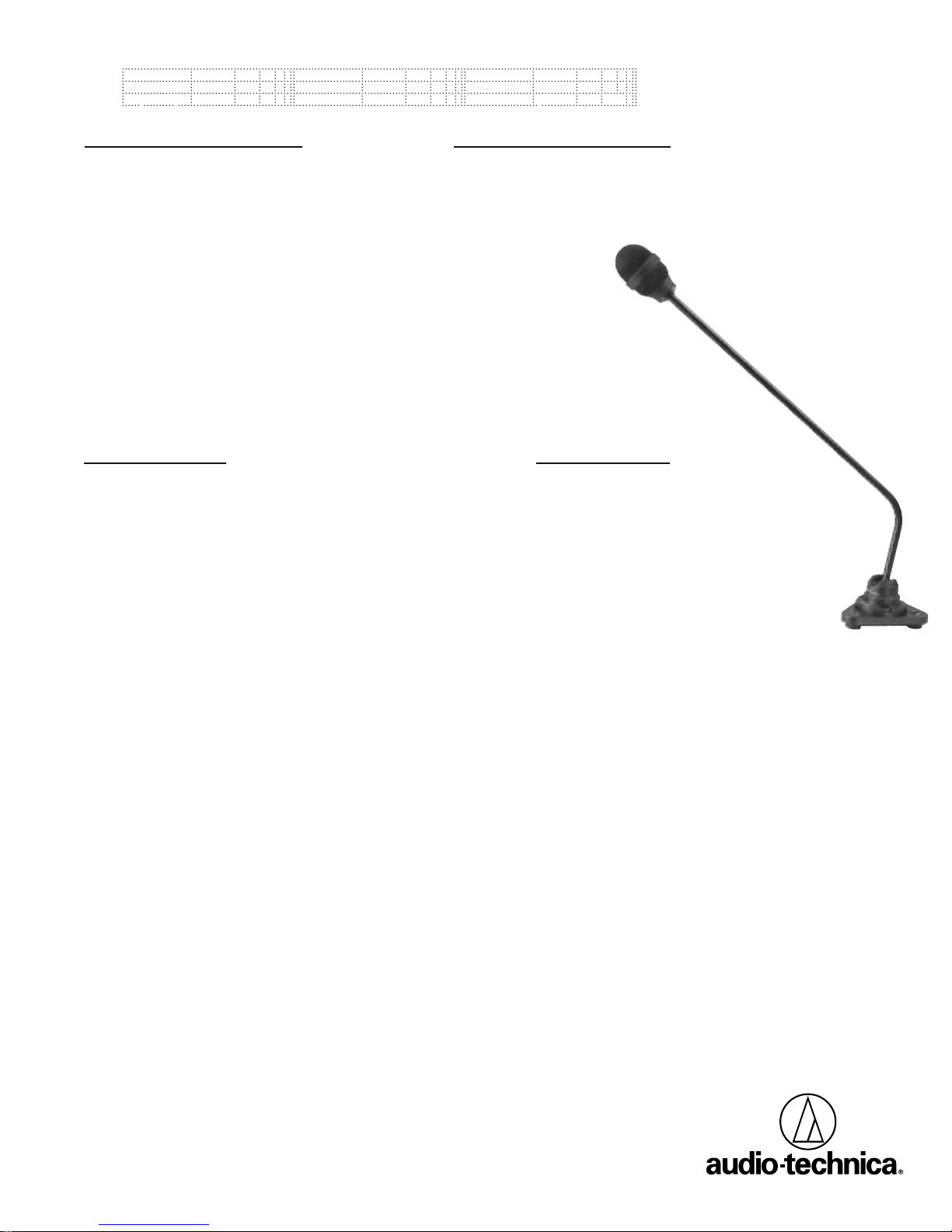
The ES993 is a dual-element cardioid
condenser microphone with a remote dual
power module. It is designed especially for
applications requiring separate miking for PA and
broadcast. The circuit grounds for each channel
are completely isolated, greatly reducing the
potential for hum. The rigid-pipe design with
ball-in-socket base permits flexible positioning.
Each of the cardioid elements in the
microphone is shock mounted. The cardioid
polar pattern of the elements provides a 120°
angle of acceptance. Additional userinterchangeable hypercardioid (100°) and
omnidirectional (360°) elements are available.
The ES993 is designed with dual integral windscreens to ensure maximum security against
wind noise and plosives.
The remote power module can be powered
from any external 11V to 52V DC phantom
Engineered Sound
Position the remote switch bezel so that the hole
lines up with the oval cut in the bezel. Install the
bezel using the two #6 x
1
/2" zinc-plated screws.
Pass the flex cable of the remote switch through
the holes in the bezel and the table. Peel the
backing from the rear of the switch pad to
expose the adhesive, and press the switch into
position on the bezel.
Final connection:
1. Attach the connector assembly to the
microphone cable. A small,flat-blade screwdriver
is required for this procedure.
a. The braided shield wire connects to pin 1.
b. The green, grey, red, blue, yellow, and white
wires connect to pins 2–7, respectively.
c. Tighten the binding screws securely and test
mic wires to make certain they are secure.
2. Connect the remote switch flex cable to
pins 1–3 on the power module. The flex cable is
in the correct position if the printed “1” on
the cable matches up with the #1 position on
the connector. (For your convenience, the
position numbers are also printed on the top
cover of the power module.)
3. Connect the female 7-pin terminal of the mic
cable to pins 4–10 on the power module.
Observe the keying of the connector as it is
inserted.
4. Connect the in-house and broadcast cables to
the 3-pin XLRM outputs. It is highly recommended to connect the primary in-house feed to Mic
Out A and the remote feed to Mic Out B.
ATTENTION! For muting to operate,
Channel A must be connected. If only Channel B
output is used, the microphone element will
operate, but the mute function will not.
While a modern condenser microphone is not
unduly sensitive to the environment,temperature
extremes can be harmful. Avoid leaving the
microphone in the open sun or in areas where
temperatures exceed 110° F (43° C) for long
periods of time. Extremely high humidity should
also be avoided.
The ES993 requires a phantom power supply
of 11–52V DC for each element. Output is
low-impedance balanced. The balanced signal
appears across Pins 2 and 3, while the ground
(shield) connection is Pin 1. Output is phased so
that positive acoustic pressure produces positive
voltage at Pin 2, in accordance with industry
convention.
The ES993 microphone is intended for
mounting to a hard surface such as a table, desk,
or podium. The microphone is supplied with
four #6 x
1
/2" black oxide wood screws for
mounting the AT8510 power module, three
#8 x 1" black oxide wood screws for mounting
the microphone, and two #6 x
1
/2" zinc-plated
wood screws for mounting the switch bezel.
To install the microphone:
Drill a 4 mm (
5
/32") hole centered in the area
where the microphone mount is to be
positioned. Pass the cable extending from the
microphone mount through this hole, and then
mount the microphone into position using the
three #8 x 1" screws.
To install the power module:
1. Be certain to set internal switches SW1 and
SW2 for desired output level and muting
operation prior to installing the power module.
To access the circuit board, remove the four
side screws and the four top screws on the top
cover. On the circuit board, set the switches
(SW1 and SW2) to the desired settings. SW1
may be set to Normal or 15 dB Pad. SW2 may
be set to Mute,Toggle, or Talk.
2. Find a convenient location on the underside
of the mounting surface to install the power
module, keeping in mind that the flex cable from
the remote switch to the power module is eight
inches long. Mount the power module into position using the four #6 x
1
/2" black oxide screws.
To install the remote switch:
Install this switch if you plan to use the mute
feature.You may install the microphone without
the mute switch if muting is not needed.
Drill a 10 mm (
3
/8") hole centered in the area
where the remote switch is to be installed.
[
Installation and Operation
]
[
[
ES993
Dual-element
Cardioid Condenser
Rigid-pipe Microphone
Page 2
Form No.0309-2129-00 P51564 © 2003 Audio-Technica U.S., Inc. Printed in U.S.A.
Elements Two fixed-charge
back plate
permanently
polarized condensers
Polar Pattern Cardioid
Frequency Response 90–15,000 Hz
Low-frequency Roll-off Fixed 120 Hz,
12 dB/octave
Open Circuit Sensitivity – 41 dB (8.9 mV)
re 1V at 1 Pa
*
Impedance 250 ohms
Maximum Input Sound 138 dB SPL, 1 kHz at
Level 1% T.H.D.
Dynamic Range 109 dB, 1 kHz at
(Typical) Max SPL
Signal-to-noise Ratio
1
65 dB, 1 kHz at 1 Pa
*
Switches SW1: Normal /– 15
dB; SW2: Mute/
Toggle/Talk
(on circuit board)
Phantom Power 11–52V DC, 3 mA
Requirements typical
Weight
Microphone (less cable) 12.0 oz (340 g)
Power Module 7.5 oz (214 g)
Dimensions
Microphone 18.50" (469.9 mm)
maximum length,
1.51" (38.4 mm)
head diameter
Power Module 5.12" (130.0 mm)
long, 1.73" (44.0 mm)
high, 2.36" (60.0 mm)
wide
Output Connectors Two 3-pin XLRM(Power Module) type
Cables 18" (457.2 mm) long
(permanently
attached to
microphone), 6conductor shielded
cable, attaches to
power module. 8"
(203.2 mm) long,
3-conductor remote
switch flex cable,
attaches to power
module
Accessories Furnished AT8510 power
module, membrane
switch, membrane
switch bezel, four #6
x 1/2" black oxide
wood screws for
AT8510, three #8 x
1" black oxide wood
screws for
microphone mount,
two #6 x 1/2" zincplated wood screws
for switch bezel
mount
Optional ESE-H hypercardioid
Interchangeable (100°)
Elements ESE-O
omnidirectional
(360°)
†
In the interest of standards development, A.T.U.S. offers full details
on its test methods to other industry professionals on request.
*
1 Pascal = 10 dynes/cm2= 10 microbars = 94 dB SPL
1
Typical, A-weighted, using Audio Precision System One.
Specifications are subject to change without notice.
One-Year Limited Warranty
Audio-Technica microphones and accessories purchased in the U.S.A. are warranted for one year from date of
purchase by Audio-Technica U.S., Inc. (A.T.U.S.) to be free of defects in materials and workmanship. In event of such
defect, product will be repaired promptly without charge or, at our option, replaced with a new product of equal or
superior value if delivered to A.T.U.S. or an Authorized Service Center, prepaid, together with the sales slip or other
proof of purchase date.
Prior approval from A.T.U.S. is required for return.
This warranty excludes defects due
to normal wear, abuse, shipping damage, or failure to use product in accordance with instructions. This warranty
is void in the event of unauthorized repair or modification.
For return approval and shipping information,
contact the Service Department, Audio-Technica U.S., Inc., 1221
Commerce Drive, Stow, Ohio 44224.
Except to the extent precluded by applicable state law,
A.T.U.S. will have no liability for any consequential,
incidental, or special damages; any warranty of merchantability or fitness for particular purpose expires
when this warranty expires.
This warranty gives you specific legal rights, and you may have other rights, which vary from state to state.
Outside the U.S.A., please contact your local dealer for warranty details.
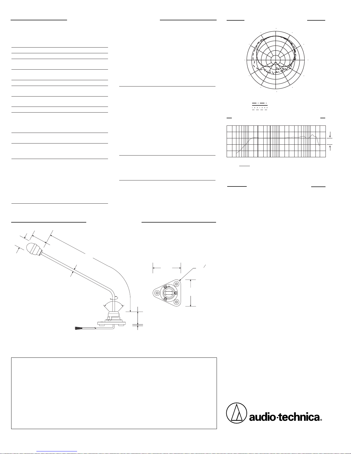
[
Dimensions
]
[
ES993 Specifications
†
]
184°
75°
1.51"
38.4 mm
2.20"
56.0 mm
14.65"
372.0 mm
0.32"
8.1 mm
1.49"
37.9 mm
0.16"
4.0 mm
3.11"
79.0 mm
3.26"
82.8 mm
3 – o 0.18"
4.5 mm
[
Polar Pattern
]
SCALE IS 5 DECIBELS PER DIVISION
200 Hz
LEGEND
5 kHz
1 kHz
8 kHz
240
180
210
270
300
330
0
150
120
90
30
60
[
Visit our Web site at www.audio-technica.com
]
Audio-Technica U.S., Inc.
1221 Commerce Drive, Stow, Ohio 44224
[
Frequency Response
]
12" or more on axis
10050200
LEGEND
10k
5k
1k
500
2k
20k
Frequency in Hertz
y
Response in dB
10 dB
The microphone shall be a dual-element,
fixed-charge condenser with a frequency
response of 90 Hz to 15,000 Hz and a
cardioid polar pattern with uniform 120°
angle of acceptance. It shall contain two
shock-mounted cardioid elements with
optically coupled isolated grounds. It shall
operate from an external 11V to 52V DC
phantom power source. It shall be capable
of handling sound input levels up to 138 dB
with a dynamic range of 109 dB. It shall have
a fixed low-frequency roll-off of 120 Hz, 12
dB/octave. Output shall be low-impedance
balanced (250 ohms).
The microphone shall be a smalldiameter, rigid-pipe design. The microphone
shall have a separate dual power module
with two 3-pin XLRM-type connectors for
direct connection to 3-pin XLRF-type
cables. The circuit board shall include a
switch for 15 dB pad, as well as a threemode mute switch.
The microphone’s overall length shall be
18.50" (469.9 mm). Head diameter shall
be 1.51" (38.4 mm). The microphone
assembly (less cable) shall weigh 12.0 oz
(340 g). The power module dimensions shall
be 5.12" (130.0 mm) W x 1.73" (44.0 mm)
H x 2.36" (60.0 mm) D. The power module
shall weigh 7.5 oz (214 g). Finish shall be
low-reflectance black.
The Audio-Technica ES993 is specified.
Architects and
Engineers
Specifications
[
[
 Loading...