

Page 1
ES935H6
C
B
A
HYPERCARDIOID CONDENSER
GOOSENECK MICROPHONE
DESCRIPTION
The ES935H6 is a wide-range miniature condenser microphone with
a hypercardioid polar pattern. It
is designed for quality sound
reinforcement, professional recording,
television and other demanding sound
pickup applications. The small-diameter
gooseneck design permits highly
flexible positioning while maintaining
a smooth, well-contoured appearance.
An included snap-on foam windscreen
effectively reduces wind noise and
“popping.”
The ES935H6 is equipped with
UniGuard
®
RFI-shielding technology,
which offers outstanding rejection of
radio frequency interference (RFI).
The microphone is RoHS compliant –
free from all substances specified in
the EU directive on hazardous
substances.
The microphone's hypercardioid polar
pattern provides a 100° angle of
acceptance. Additional interchangeable
elements with omnidirctional (360°), cardioid (120°) and MicroLine
(90°) pickup patterns are available.
The integral power module can be powered from any external 11V
to 52V DC phantom power supply. A recessed switch in the power
module permits choice of flat response or low-frequency roll-off
(via integral 80 Hz high-pass UniSteep
®
filter) to help control
undesired ambient noise.
The microphone is enclosed in a rugged housing with a lowreflectance black finish. It features an XLRM-type connector insert
at its base, allowing it to be plugged directly into an XLRF-type
panel jack or microphone cable. In addition to an AT8474 lowprofile isolation mount, an AT8473 stand clamp is included to
permit attachment of the XLR mic base to a standard
3
/8"-16 threaded mic stand or mounting flange.
5
/8"-27 or
INSTALLATION AND OPERATION
The ES935H6 requires 11V to 52V phantom power for operation.
Output is low impedance balanced. The output connector mates
with XLRF-type cable connectors. The balanced signal appears
across Pins 2 and 3, while the ground (shield) connection is Pin 1.
Output is phased so that positive acoustic pressure produces
positive voltage at Pin 2, in accordance with industry convention.
ARCHITECTS AND ENGINEERS SPECIFICATIONS
The microphone shall be a fixed-charge condenser designed
for permanent installation or portable applications. It shall have a
hypercardioid polar pattern with uniform 100° angle of acceptance
and shall be capable of accepting optional interchangeable
elements for additional polar patterns. It shall have a frequency
response of 80 Hz to 20,000 Hz and be capable of handling sound
input levels up to 138 dB with a dynamic range of 109 dB. Nominal
open-circuit output voltage shall be 10.0 mV at 1 kHz, 1 Pascal.
Output shall be low impedance balanced (250 ohms).
The microphone shall operate from an external 11V to 52V DC
phantom power source. It shall offer outstanding rejection of radio
frequency interference (RFI).The microphone shall be RoHS compliant.
The microphone shall be a gooseneck design permitting highly
flexible positioning and noiseless operation. It shall incorporate a
self-contained power module with an XLRM-type connector at the
base for direct connection to a mating XLRF-type panel jack or
cable connector. The power module shall include a recessed
switch for low-frequency roll-off. The low-frequency roll-off shall be
a tailored roll-off at 80 Hz to minimize pickup of unwanted
mechanical noise.
A universal isolation-type shock mount suitable for above or below
surface installation shall be supplied for mounting the microphone
®
in a solid surface. It shall be possible to firmly secure the
microphone in the mount. The mount shall include appropriate
hardware for installation. For alternative mounting and portable
applications, the microphone shall be supplied with a stand clamp
to permit attaching the microphone directly to a standard
3
/8"-16 thread. A snap-on foam windscreen shall also be included.
5
/8"-27 or
The microphone shall be a small-diameter gooseneck design, with
an overall length of 7.77" (197.3 mm). Head diameter shall be
0.33" (8.4 mm). The microphone weight shall be 3.7 oz
(104 grams). Finish shall be low reflectance black.
The Audio-Technica ES935H6 is specified.
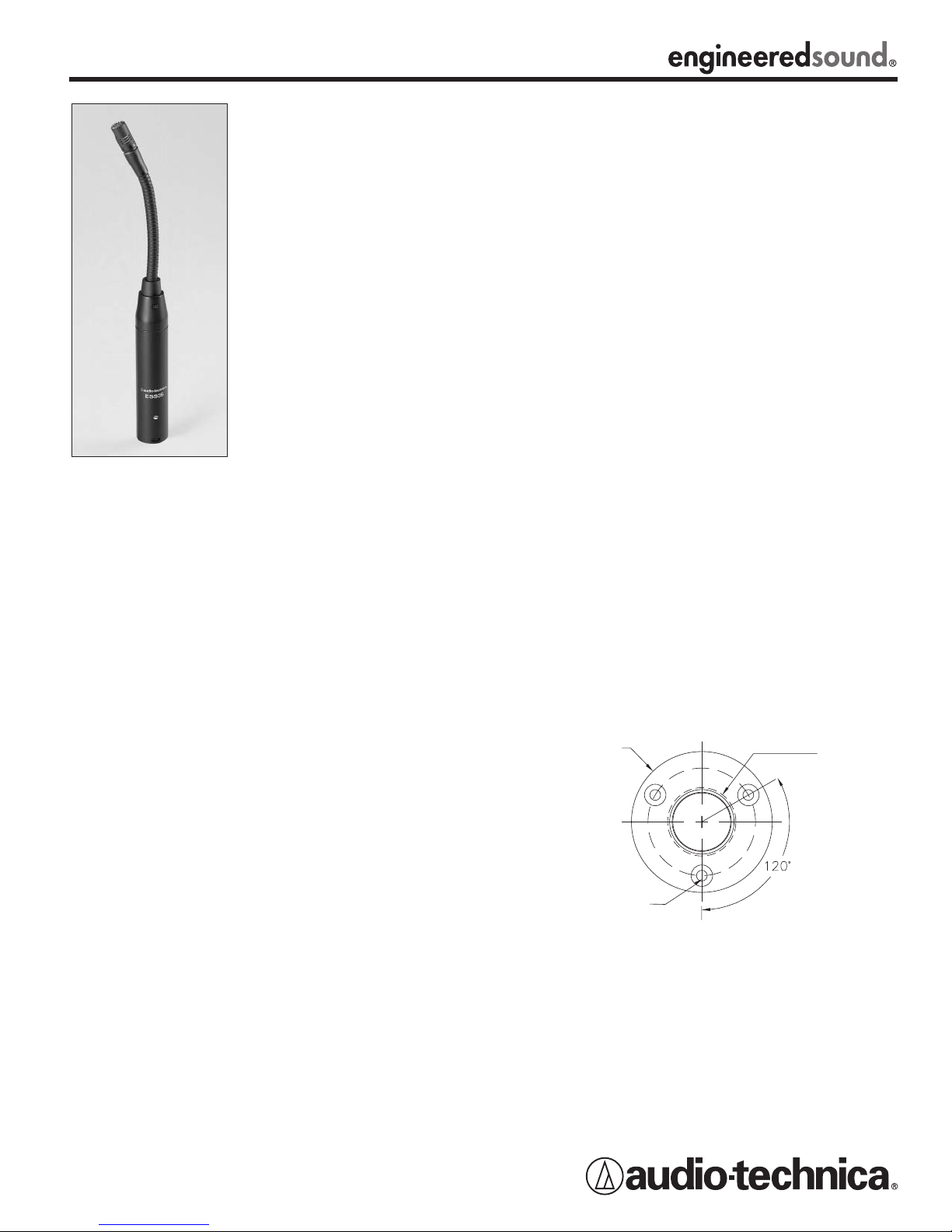
AT8474 LOW-PROFILE ISOLATION MOUNT INSTALLATION
INSTRUCTIONS
MOUNTING DIMENSIONS
1
/16" (1.5 mm) pilot holes 3 places on 1.57" (40.0 mm) circle.
A.
B. 1.00" (25.4 mm) hole through the mounting surface.
C. Outside edge of mount, 2.06" (52.4 mm) diameter.
The microphone can be mounted on a podium or desktop with the
included AT8474 low-profile isolation mount. Designed to be
mounted either above or beneath the mounting surface, the
AT8474 firmly secures the microphone while providing maximum
attenuation of noise, shock and vibration transmitted through the
mounting surface. Installation details are provided on the back of
this sheet. An AT8473 stand clamp is also included to permit
attachment of the XLR mic base to a standard
threaded mic stand or mounting flange.
The provided snap-on foam windscreen simply slips over the
element, effectively reducing wind noise and “popping.”
®
An integral 80 Hz high-pass UniSteep
filter provides easy switching
from a flat frequency response to a low-end roll-off. The roll-off
position reduces the pickup of low-frequency ambient noise (such
as traffic, air-handling systems, etc.), room reverberation and
mechanically coupled vibrations. To engage the UniSteep
use the end tip of a paperclip or other small pointed instrument to
slide the switch toward the “bent” line.
While a modern condenser microphone is not unduly sensitive to
the environment, temperature extremes can be harmful. Exposure
to high temperature can result in gradual and permanent reduction
of the output level. Avoid leaving the microphone in the open sun or
in areas where temperatures exceed 110° F (43° C) for long
periods of time. Extremely high humidity should also be avoided.
5
/8"-27 or 3/8"-16
®
filter,
Drawing not actual size.
1. The AT8474 mount can be mounted either above or below the
table surface.
2. Locate the center of the mounting location and mark it.
Allow
enough clearance to accommodate the AT8474 mount on
the desired surface and make certain there are no physical
obstructions below the desired location.
3. Locate the three mounting screw holes and mark them.
Continued on back.
Page 2
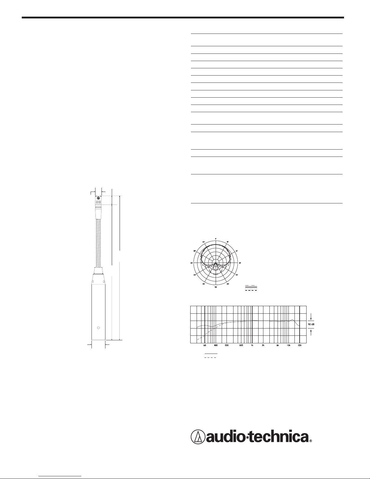
8 kHz
Polar Pattern
SCALE IS 5 DECIBELS PER DIVISION
LEGEND
200 Hz
1 kHz
5 kHz
Frequency in Hertz
LEGEND
12" or more on axis
Frequency Response
Response in dB
Roll-off
4. Using a 1" hole saw, drill the through-hole for the microphone
0.48"
12.3 mm
0.33"
8.4 mm
7.77"
197.3 mm
7.28"
185.0 mm
0.74"
18.9 mm
body. (Note: although a 1" drill bit will work, a hole saw provides
for a cleaner hole and is less likely to damage the table surface.)
1
5. Using a
/16" (1.5 mm) drill bit, drill three pilot holes for the
mounting screws. (If mounting below the table surface, be
NOT to drill pilot holes through the table.)
certain
6. Place the AT8474 mount over the hole and partially tighten the
three screws. Then place the microphone in the AT8474 so that
the microphone's power module (base) extends through the
AT8474 mount into the hole. Tighten all three screws evenly.
For maximum security, the screws should be tight enough to
ensure that the microphone is held securely in place and can
not be removed without loosening the screws.
7. If mounting the AT8474 mount below the surface of the table,
slide the rubber trim ring over the microphone (above the table
surface) and seat it between the microphone and the sides of
the hole for a finished appearance. (If mounting the AT8474
above the surface of the table, you may also choose to use the
trim ring beneath the surface of the table, for added attenuation
of noise, shock and vibration.)
8. After installing the microphone, assure maximum shock mount
effectiveness by providing some slack in the connecting cable.
The cable can be secured to the table with a standard wire clip
or cable tie (not included).
ES935H6 SPECIFICATIONS
†
ELEMENT Fixed-charge back plate
permanently polarized condenser
POLAR PATTERN Hypercardioid
FREQUENCY RESPONSE 80-20,000 Hz
LOW-FREQUENCY ROLL-OFF 80 Hz, 18 dB/octave
OPEN CIRCUIT SENSITIVITY –40 dB (10.0 mV) re 1V at 1 Pa*
IMPEDANCE 250 ohms
MAXIMUM INPUT SOUND LEVEL 138 dB SPL, 1 kHz at 1% T.H.D.
DYNAMIC RANGE (typical) 109 dB, 1 kHz at Max SPL
SIGNAL-TO-NOISE RATIO
1
65 dB, 1 kHz at 1 Pa*
SWITCH Flat, roll-off
PHANTOM POWER 11-52V DC, 4 mA typical
REQUIREMENT
WEIGHT 104 g (3.7 oz)
DIMENSIONS 197.3 mm (7.77") long,
8.4 mm (0.33") head diameter,
18.9 mm (0.74") base diameter
OUTPUT CONNECTOR Integral 3-pin XLRM-type
OPTIONAL INTERCHANGEABLE ESE-O omnidirectional (360°);
ELEMENTS ESE-C cardioid (120°);
ESE-ML MicroLine®(90°)
ACCESSORIES FURNISHED AT8109 two-stage foam
windscreen; AT8474 universal
isolation mount; AT8473 quickmount stand adapter;
3
/8"-16 threaded adapter
†In the interest of standards development, A.T.U.S. offers full details on its test
methods to other industry professionals on request.
*1 Pascal = 10 dynes/cm
1
Typical, A-weighted, using Audio Precision System One.
Specifications are subject to change without notice.
2
= 10 microbars = 94 dB SPL
5
/8"-27 to
Audio-Technica U.S., Inc., 1221 Commerce Drive, Stow, Ohio 44224
Audio-Technica Limited, Old Lane, Leeds LS11 8AG England
www.audio-technica.com
P51932 ©2007 Audio-Technica U.S., Inc. Printed in U.S.A.
 Loading...