

Audio Technica ES935, ES935/C Installation And Operating
[
Description
]
The integral power module can be powered
from any external 11V to 52V DC phantom
power supply. A recessed switch in the power
module permits choice of flat response
or low-frequency roll-off to help control
undesired ambient noise.
The microphone is enclosed in a rugged
housing with a low-reflectance black finish. It
features an XLRM-type connector insert at its
base, allowing it to be plugged directly into an
XLRF-type panel jack or microphone cable. In
addition to an AT8658 heavy-duty shock
mount, an AT8651 thread-mount adapter is
included to permit attachment of the XLR mic
base to a standard
5
/8"-27 threaded mic stand
or mounting flange.
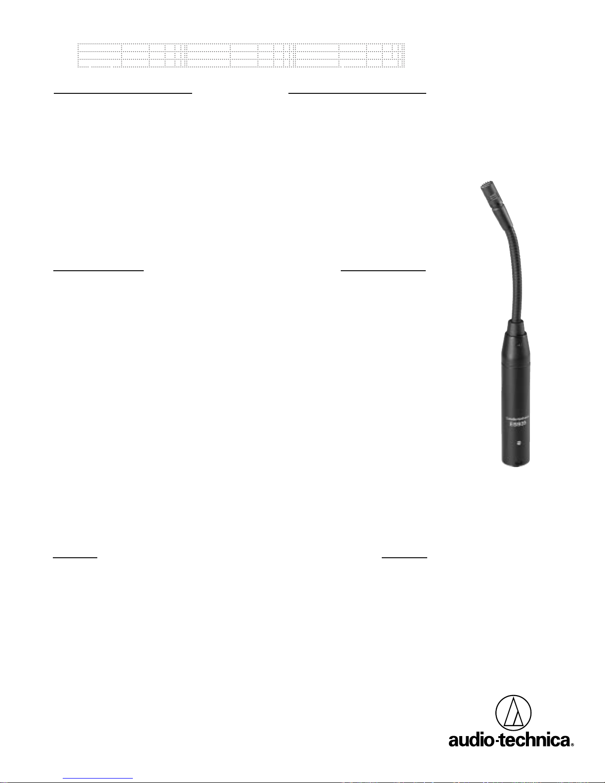
The ES935/C is a wide-range condenser
microphone with a cardioid polar pattern. It is
designed for quality sound reinforcement,
professional recording, television and other
demanding sound pickup applications. The
small-diameter gooseneck design permits
highly flexible positioning while maintaining a
smooth, well-contoured appearance. An
included snap-on foam windscreen effectively
reduces noise from wind or ventilation air
currents.
The cardioid polar pattern provides a 120°
angle of acceptance. Additional interchangeable elements with hypercardioid (100°) and
MicroLine
®
(90°) pickup patterns are available.
Engineered Sound
[
[
ES935/C
Cardioid Condenser
Gooseneck Microphone
used, the diameter of the cable should be 0.2"
(5 mm) maximum. Solder the conductors to
the XLRF insert using Pin 1 as ground (shield),
Pin 2 as positive (signal hot), and Pin 3 as negative (signal common). Reassemble the adapter
mount and test the wiring.
The provided snap-on foam windscreen
simply slips over the element, effectively
reducing wind noise or “popping” when used
extra close.
The small-diameter gooseneck is easy to
manipulate for proper positioning. Heavily
lubricated, it operates smoothly and quietly.
Should the unit become noisy with prolonged
use, apply a light machine oil directly on the
gooseneck area affected.
While a modern condenser microphone
is not unduly sensitive to the environment,
temperature extremes can be harmful.
Exposure to high temperature can result in
gradual and permanent reduction of the output level. Avoid leaving the microphone in the
open sun or in areas where temperatures
exceed 110° F (43° C) for long periods of
time. Extremely high humidity should also be
avoided.
Output is low impedance balanced. The
output connector mates with XLRF-type
cable connectors. The balanced signal appears
across Pins 2 and 3, while the ground (shield)
connection is Pin 1. Output is phased so that
positive acoustic pressure produces positive
voltage at Pin 2, in accordance with industry
convention.
The microphone can be mounted on a
podium or desktop with the included AT8658
shock mount. A special isolator attenuates
noise, shock and vibration transmitted through
the mounting surface. Installation details are
provided on the back of this sheet.
The microphone can also be mounted
using the AT8651 mounting adapter. The
microphone inserts directly into the XLRFtype connector end of the adapter, while the
other end is
5
/8"-27 threaded to allow connection to a standard microphone desk/floor
stand, or a mounting flange on a podium or
desktop. To install: Disassemble the XLRF
insert from the adapter body. Route the mic
cable (2-conductor shielded, not supplied)
either through the side hole or from the
bottom of the adapter body. If the side hole is
The microphone shall be a fixed-charge
condenser with a frequency response of
30 Hz to 20,000 Hz and a cardioid polar
pattern with uniform 120° angle of acceptance. It shall be capable of accepting optional
interchangeable elements for additional polar
patterns. It shall operate from an external 11V
to 52V DC phantom power source. It shall be
capable of handling sound input levels up to
138 dB with a dynamic range of 109 dB.
Nominal open-circuit output voltage shall be
10.0 mV at 1 kHz, 1 Pascal. Output shall be
low impedance balanced (250 ohms).
The microphone shall have a self-contained
power module with an XLRM-type connector
at the base for direct connection to a mating
[
Architects and Engineers Specifications
]
XLRF-type panel jack or cable connector. The
power module shall include a recessed switch
for low-frequency roll-off. A shock mount
shall be supplied for mounting in a solid
surface. An included mounting adapter shall
permit attaching the microphone directly to a
standard
5/
8
"-27 thread. A snap-on foam wind-
screen shall also be included.
The microphone shall be a small-diameter
gooseneck design, with an overall length of
7.52" (191.0 mm). Head diameter shall be
0.33" (8.4 mm). The microphone weight shall
be 3.2 oz (92 grams). Finish shall be lowreflectance black.
The Audio-Technica ES935/C is specified.
[
Installation and Operation
]
[
ES935/C Specifications
†
]
Form No.0309-2110-01-B/W P51271-01 © 2002 Audio-Technica U.S., Inc. Printed in U.S.A.
Element Fixed-charge back
plate permanently
polarized condenser
Polar Pattern Cardioid
Frequency Response 30-20,000 Hz
Low-frequency Roll-off 80 Hz, 12 dB/octave
Open Circuit Sensitivity –40 dB (10.0 mV)
re 1V at 1 Pa
*
Impedance 250 ohms
Maximum Input Sound 138 dB SPL, 1 kHz at
Level 1% T.H.D.
Dynamic Range 109 dB, 1 kHz at
(Typical) Max SPL
Signal-to-noise Ratio
1
65 dB, 1 kHz at 1 Pa
*
Switch Flat response,
low-roll-off
(recessed)
Phantom Power 11-52V DC, 4 mA
Requirements typical
Weight 3.2 oz (92 grams)
Dimensions 7.52" (191.0 mm)
long,
0.33" (8.4 mm)
head diameter,
0.74" (18.9 mm)
base diameter
Output Connector Integral 3-pin
XLRM-type
Accessories Furnished AT8109 snap-on
foam windscreen;
AT8651threadmount adapter;
AT8658 shock
mount
Optional ESE-H hypercardioid
Interchangeable (100°)
Elements ESE-ML MicroLine
®
(90°)
†
In the interest of standards development,A.T.U.S. offers full details
on its test methods to other industry professionals on request.
*
1 Pascal = 10 dynes/cm2= 10 microbars = 94 dB SPL
1
Typical,A-weighted, using Audio Precision System One.
Specifications are subject to change without notice.
Outside the U.S.A., please contact your local dealer for warranty details.
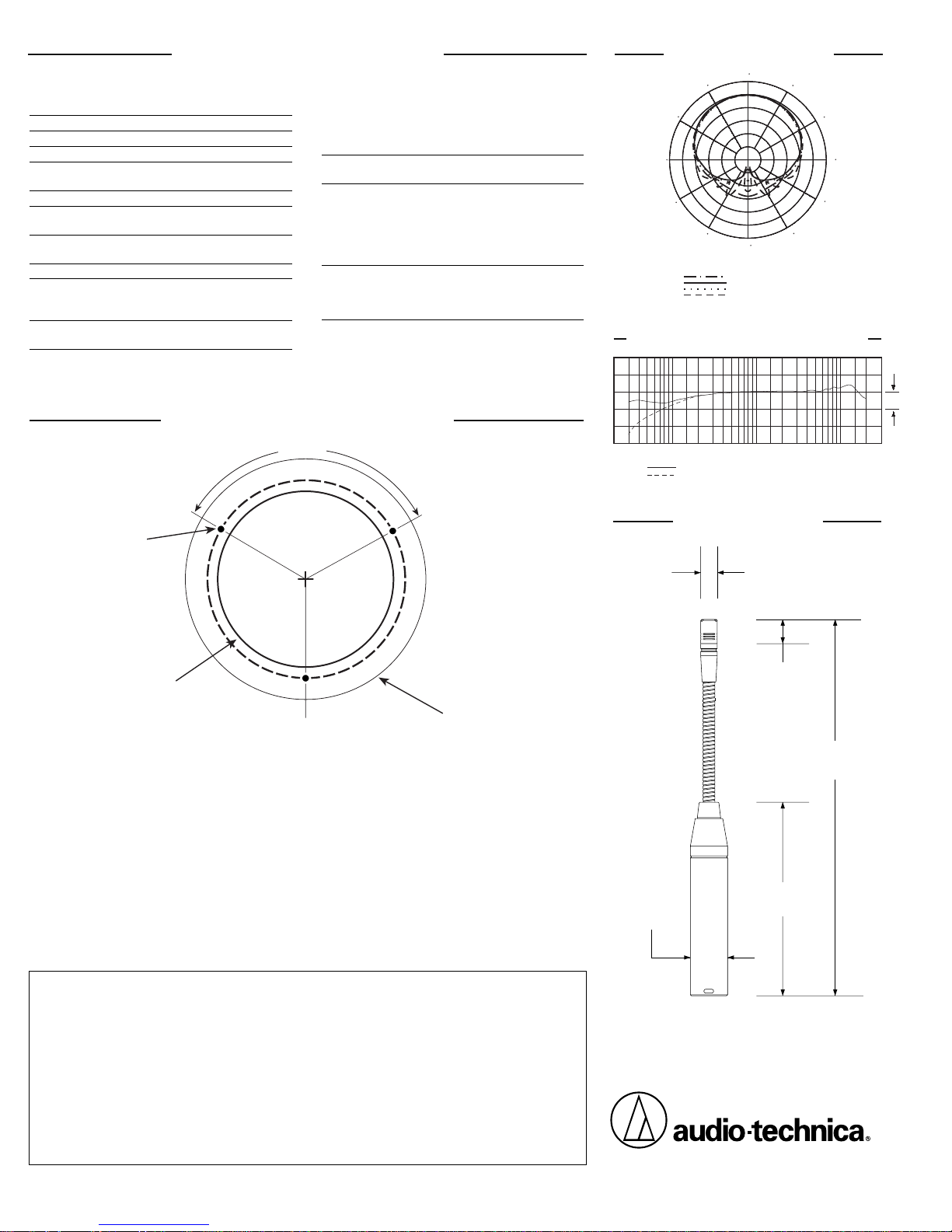
98.5 mm
3.88"
0.48"
12.3 mm
7.52"
191.0 mm
0.74"
18.9 mm
8.4 mm
0.33"
[
Dimensions
]
[
Polar Pattern
]
90
270
200 Hz
8 kHz
1 kHz
5 kHz
LEGEND
240
SCALE IS 5 DECIBELS PER DIVISION
180
210
120
150
300
330
60
30
0
One-Year Limited Warranty
Audio-Technica microphones and accessories purchased in the U.S.A. are warranted for one year from date of purchase by Audio-Technica U.S., Inc. (A.T.U.S.) to be free of defects in materials and workmanship. In event of such
defect, product will be repaired promptly without charge or, at our option, replaced with a new product of equal or
superior value if delivered to A.T.U.S. or an Authorized Service Center, prepaid, together with the sales slip or other
proof of purchase date.
Prior approval from A.T.U.S. is required for return.
This warranty excludes defects due
to normal wear, abuse, shipping damage, or failure to use product in accordance with instructions. This warranty
is void in the event of unauthorized repair or modification.
For return approval and shipping information,
contact the Service Department, Audio-Technica U.S., Inc., 1221
Commerce Drive, Stow, Ohio 44224.
Except to the extent precluded by applicable state law,
A.T.U.S. will have no liability for any consequential,
incidental, or special damages; any warranty of merchantability or fitness for particular purpose expires
when this warranty expires.
This warranty gives you specific legal rights, and you may have other rights which vary from state to state.
[
Visit our Web site at www.audio-technica.com
]
[
Shock Mount Installation
]
B
C
3
x
1
2
0
˚
FRONT
A
1. Locate the center of the mounting location and mark it. Allow enough clearance to
accommodate the shock mount's flange on the desired surface and make certain there are no
physical obstructions below the desired location.
2. Using a 21/4" (57 mm) hole saw, drill the large through-hole for the shock mount.
3. Set the shock mount into the hole and mark the location of the three mounting screw
holes.
Make certain to "center" the mount in the large hole before marking the three small
mounting screw locations.
4. Using a 1/16" (1.5 mm) drill bit, drill three pilot holes for the mounting screws.
5. After installing the microphone, assure maximum shock mount effectiveness by providing
some slack in the connecting cable.
AT8658
Mounting Dimensions
A.1/16" (1.5 mm)
pilot holes 3 places on
21/2" (64 mm) circle.
B. 21/4" (57 mm)
thru-hole for mount
clearance.
C. Outside edge of
flange, 3.07" (78 mm)
diameter.
Drawing not actual size.
Audio-Technica U.S., Inc.
1221 Commerce Drive, Stow, Ohio 44224
[
Frequency Response
]
20k
200
Roll-off
12" or more on axis (flat)
LEGEND
50
100
2k
Frequency in Hertz
500
1k
5k
10k
Response in dB
10 dB
 Loading...