

Page 1
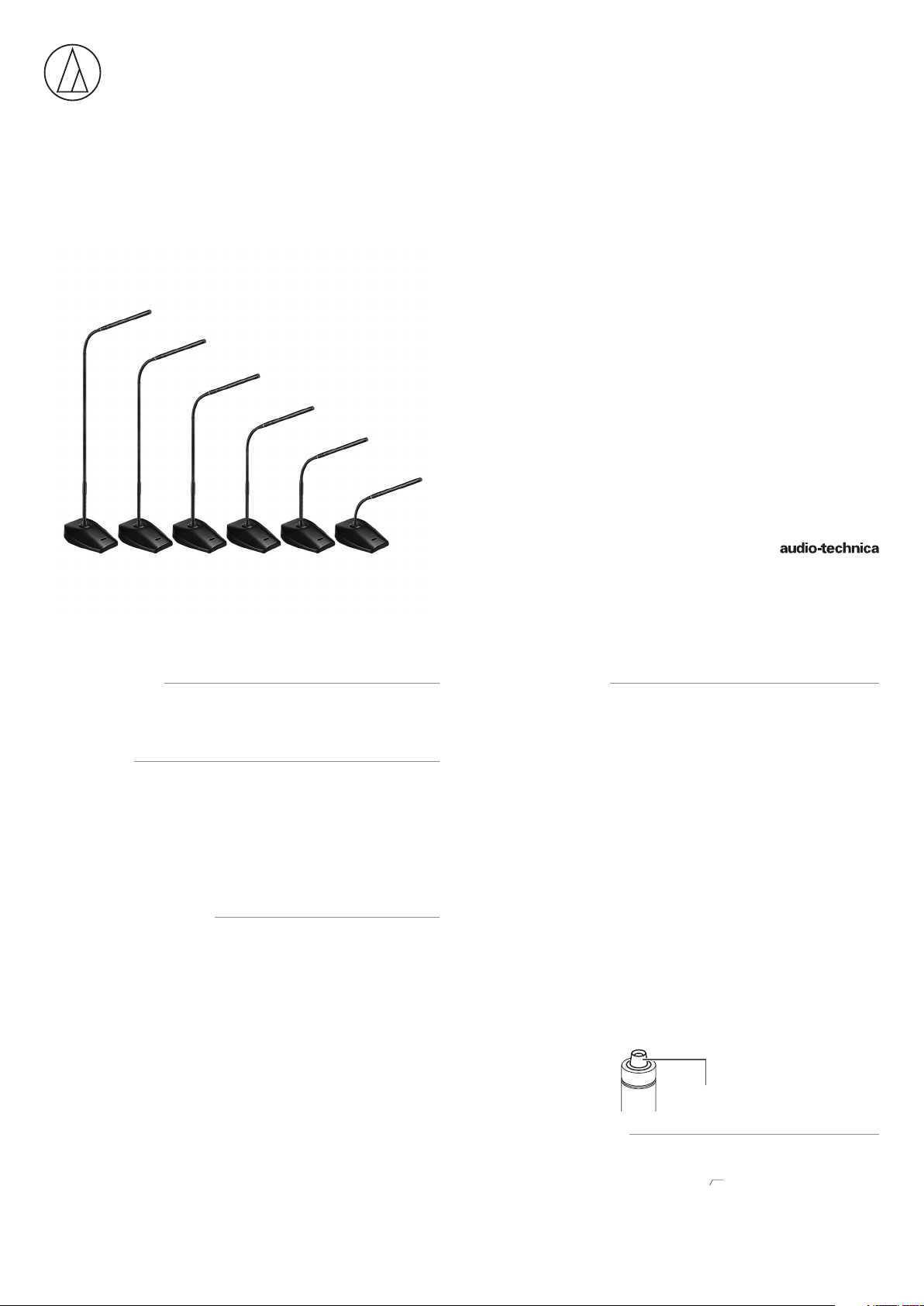
ES925ML6/DS5
ES925ML12/DS5
ES925ML15/DS5
ES925ML18/DS5
ES925ML21/DS5
ES925ML24/DS5
User Manual
MICROLINE CONDENSER
MODULAR GOOSENECK MICROPHONE
WITH 5-PIN DESK STAND POWER MODULE
■Introduction
Thank you for purchasing this product. Before using the product, read through
the user manual to ensure that you will use the product correctly. Please keep
this manual for future reference.
■Features
• Modular microphone system comprised of an ES Series capsule, gooseneck
assembly, and power module.
• RGB LEDs built into both the desk stand power module and gooseneck
assembly indicate the on/off status of the microphone.
• Includes external control function for device control from the capacitive touch
switch.
• The capacitive touch switch can be set to any of three operating modes:
“touch-on/touch-off”, “touch-to-talk” and “touch-to-mute”.
■Safety precautions
Although this product was designed to be used safely, failing to use it correctly
may result in an accident. To ensure safety, observe all warnings and cautions
while using the product.
■Cautions for the product
• Do not subject the product to strong impact to avoid malfunction.
• Do not disassemble, modify or attempt to repair the product.
• Do not handle the product with wet hands to avoid electric shock or injury.
• Do not store the product under direct sunlight, near heating devices or in a
hot, humid or dusty place.
■Notes on use
• Do not swing or pull the product. Doing so may cause disconnection or
damage.
• The circuitry in the microphone takes about 30 seconds to stabilize after power
is supplied. You may hear some audio disturbance during startup.
• The connectors are equipped with a special RFI-shielding mechanism. If you
remove or replace the connector, you may adversely affect the microphone’s RFI
immunity. The Audio-Technica Crimp Tool (ATCT) and shield parts are required to
shorten the cable and reinstall the connector while maintaining the RFI immunity.
• Install the microphone on a flat, unobstructed mounting surface. Make sure
that the sound source is not below the mounting surface.
• Depending on the surface finish of a table, the desk stand power module may
leave marks on the table.
• Do not excessively bend the gooseneck assembly, rotate the ends of the
capsule, or pull on them. Doing so may cause disconnection or malfunction.
• The product is a modular system comprised of a microphone element,
gooseneck assembly and power module. Make sure the parts are firmly
attached before use.
• Do not remove the rubber O-ring on the power module connecting part at the
lower section of the gooseneck assembly.
• When attaching parts, remove the black cap on the capsule connecting part
of the gooseneck assembly. Do not remove the silicone part at the end of
the capsule connecting part.
Silicone part
Do not remove
■Switch settings
To reduce low-frequency ambient noise (such as footsteps or air conditioning
noise), room reverberation, and mechanically coupled vibrations as much as
possible, turn on the low-cut filter switch (
module.
1
) on the bottom of the power
Page 2
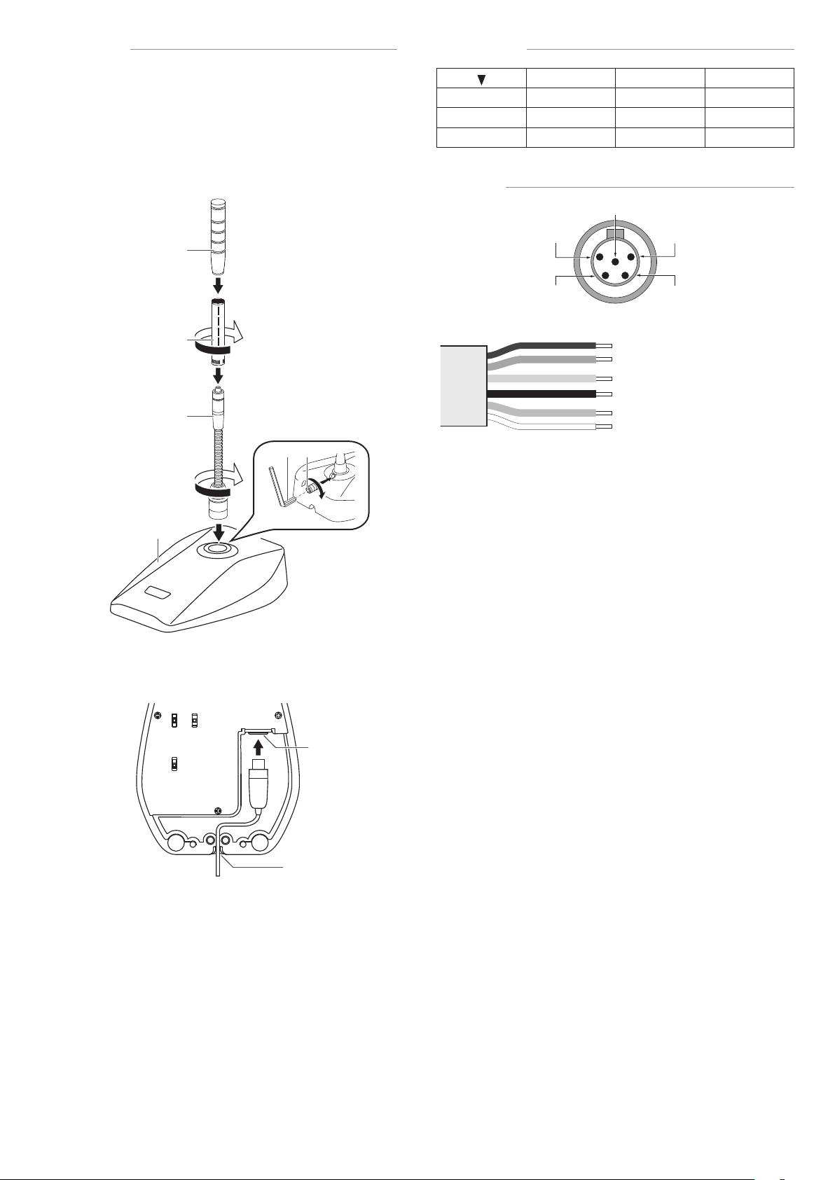
■Assembly
1
2
5
3
4
1. • Insert the gooseneck assembly (c) while rotating it into the desk stand
power module (d).
• Tighten until it does not rotate, and use the hex wrench (h) to tighten the
set screw (g) and set the gooseneck assembly in place.
• Connect the capsule (b) to the gooseneck assembly, and attach the
windscreen (a).
* If the parts are not sufficiently tightened together, problems may occur
such as the LED colors of the gooseneck assembly and power module
not matching or sound is not output.
a
■LED color
1 2 3
OFF RED GREEN
4 5 6 7
BLUE
MAGENTA
CYAN WHITE
■Wiring
YELLOW
b
c
g
h
d
2. Connect the included cable to the connector (e) on the reverse side of the
desk stand power module, and pass the cable through the wire slot (f).
SHIELD : GND (PIN1)
YELLOW : HOT (PIN2)
RED : COLD (PIN3)
BLACK : GND (PIN1)
BLUE : CONTACT CLOSURE (PIN5)
WHITE : LED CONTROL (PIN4)
e
f
2
Page 3

■Switch setting and functions
2 1
6
3, 7
Control
1.
Switch
2.
Function
Action
3.
Contact
4.
closure
status
5.
Audio
status
LED color
6.
LED status
7.
Contact
Closure
GND
MIC
4
3
Page 4

■Specifications
5020 20k10k5k2k1k500200100
ES925ML6/DS5 ES925ML12/DS5 ES925ML15/DS5 ES925ML18/DS5 ES925ML21/DS5 ES925ML24/DS5
ES925MLx/DS5
Element
Polar pattern
Frequency response
Low frequency roll-o
Open circuit sensitivity
Impedance
Maximum input sound level
Dynamic range
Signal-to-noise ratio
Switches
Phantom power
requirements
Contact closure
Closure input voltage
Maximum permissible
LED control
Active low voltage
Maximum permissible
Maximum permissible
Output connector
Optional interchangeable
Included accessories
power
On-resistance
input power
power
Weight
Dimensions
elements
x = 6/12/15/18/21/24
Fixed-charge back plate, permanently polarized condenser
Line + Gradient
30 - 20,000 Hz
80 Hz, 18 dB/octave
-35 dB (17.7mV) (0dB=1V/Pa, 1kHz)
130 ohms
137 dB SPL (1kHz at 1% THD)
114 dB (1kHz at Max SPL)
71 dB (1kHz at 1Pa, A-weighted)
Low cut: on/o;
Switch function: touch on/o, momentary on, momentary o;
Control: local, remote, LED remote
22 - 52 V DC, 8 mA
-0.5 - 5.5 V
200 mW
100 ohms
Active high (+5 V DC) TTL compatible
1.2 V or lower
-0.5 - 5.5 V
200 mW
ES925ML6/DS5: 678.2 g (23.9 oz)
ES925ML12/DS5: 702.2 g (24.8 oz)
ES925ML15/DS5: 707.2 g (24.9 oz)
ES925ML18/DS5: 712.2 g (25.1 oz)
ES925ML21/DS5: 717.2 g (25.3 oz)
ES925ML24/DS5: 722.2 g (25.5 oz)
ES925ML6/DS5: 269.5 mm (10.6“) x 97 mm (3.8“) x 130 mm (5.1“)
ES925ML12/DS5: 377 mm (14.8“) x 97 mm (3.8“) x 130 mm (5.1“)
ES925ML15/DS5: 453.2 mm (17.8“) x 97 mm (3.8“) x 130 mm (5.1“)
ES925ML18/DS5: 529.4 mm (20.8“) x 97 mm (3.8“) x 130 mm (5.1“)
ES925ML21/DS5: 605.6 mm (23.8“) x 97 mm (3.8“) x 130 mm (5.1“)
ES925ML24/DS5: 681.8 mm (26.8“) x 97 mm (3.8“) x 130 mm (5.1“)
(H×W×D)
TB5M-type
ESE-Ca (120°), ESE-Ha (100°), ESE-Oa (360°)
7.6 m (24.9') Microphone cable (TA5F, unterminated),
Windscreen AT8138a,
Set screw (M2×4 mm (0.2“)) 2 pcs., Hex wrench (0.89 mm (0.04“))
■Polar pattern
330˚
300˚
270˚
240˚
210˚
SCALE IS 5 DECIBELS PER DIVISION
180˚
■Frequency response
10dB
Response in dB
Frequency in Hertz
■Dimensions
55.0
61.5
97.0
0˚
30˚
150˚
130.0
ES8766RC (DS5)
60˚
120˚
LEGEND
90˚
LEGEND
30.0
200 Hz
1 kHz
5 kHz
8 kHz
0°, 50cm
0°, 50cm, Low cut
2-M3 P=0.5
φ8.0
605.6
529.4
377.0
453.2
269.5
Audio-Technica Corporation
2-46-1 Nishi-naruse, Machida, Tokyo 194-8666, Japan
©2019 Audio-Technica Corporation
Global Support Contact: www.at-globalsupport.com
Made in Japan
4
681.8
(unit: mm)
142419742-02-01 ver.1 2019.06.01
 Loading...