

Page 1
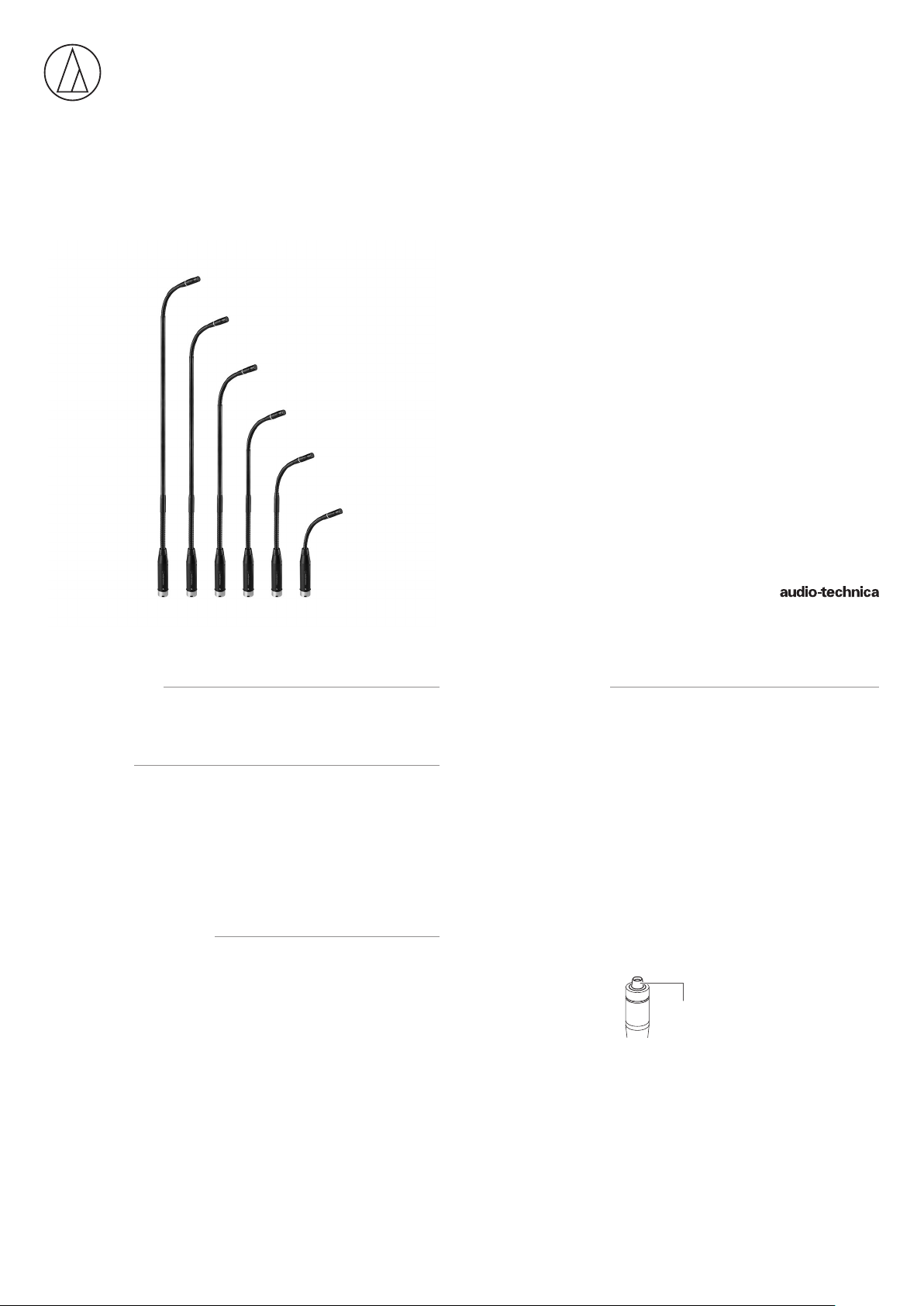
ES925C6/XLR
ES925C12/XLR
ES925C15/XLR
ES925C18/XLR
ES925C21/XLR
ES925C24/XLR
User Manual
CARDIOID CONDENSER
MODULAR GOOSENECK MICROPHONE
WITH XLR POWER MODULE
■Introduction
Thank you for purchasing this product. Before using the product, read through
the user manual to ensure that you will use the product correctly. Please keep
this manual for future reference.
■Features
• Modular microphone system comprised of an ES Series capsule, gooseneck
assembly, and power module.
• RGB LED built into the gooseneck assembly can be linked seamlessly with
ATUC Series products and the desk stand (AT8699R).
• Insert the power module into a standard XLRF-type connector, or use the
included quick mount stand adapter (AT8473) to attach it to a microphone
stand.
• Cover a wide sound acquisition range from 90° to 360° by replacing the
capsule.
■Safety precautions
Although this product was designed to be used safely, failing to use it correctly
may result in an accident. To ensure safety, observe all warnings and cautions
while using the product.
■Cautions for the product
• Do not subject the product to strong impact to avoid malfunction.
• Do not disassemble, modify or attempt to repair the product.
• Do not handle the product with wet hands to avoid electric shock or injury.
• Do not store the product under direct sunlight, near heating devices or in a
hot, humid or dusty place.
■Notes on use
• Do not swing or pull the product. Doing so may cause disconnection or
damage.
• The circuitry in the microphone takes about 30 seconds to stabilize after power
is supplied. You may hear some audio disturbance during startup.
• Check that the carry case ground is grounded with the mic cable latch firmly
engaged before use.
• Do not excessively bend the gooseneck assembly, rotate the ends of the
capsule, or pull on them. Doing so may cause disconnection or malfunction.
• The product is a modular system comprised of a microphone element,
gooseneck assembly and power module. Make sure the parts are firmly
attached before use.
• Do not remove the rubber O-ring on the power module connecting part at the
lower section of the gooseneck assembly and the lower part of the XLR power
module.
• When attaching parts, remove the black cap on the capsule connecting part
of the gooseneck assembly. Do not remove the silicone part at the end of
the capsule connecting part.
Silicone part
Do not remove
1
Page 2
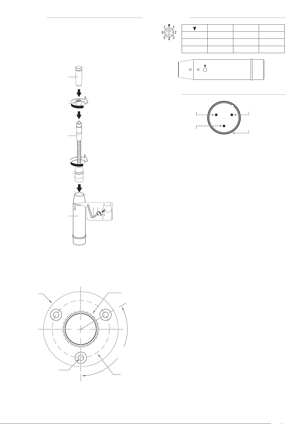
■Assembly
a
b
c
d
52.4
25.4
AT8474
1. • Insert the gooseneck assembly (c) while rotating it into the XLR power
module (d).
• Tighten until it does not rotate, and use the hex wrench (f) to tighten the
set screw (e) and set the gooseneck assembly in place.
• Connect the capsule (b) to the gooseneck assembly, and attach the
windscreen (a).
* If the parts are not sufficiently tightened together, problems may occur
such as the LED not lighting up to the set color or sound is not output.
■LED color
■Wiring
1 2 3
OFF RED GREEN
4 5 6 7
BLUE
MAGENTA
CYAN WHITE
YELLOW
e
f
2. • If you are using the AT8474, make mounting reference holes (with a
diameter of 1.5 mm (0.06") (X) on the circumference of a circle with a
diameter of 40 mm (1.6")) in the mounting surface.
• Make a hole with a diameter of 25.4 mm (1") in the center (Y) of the
mounting surface for the XLR power module.
• The outer diameter of the mounting surface is 52.4 mm (2.1") (Z).
PIN1
(LED control)
PIN3
(Cold)
1 2
3
PIN2
(Hot)
CASE
(Ground)
LED control only available with ATUC series products and AT8699R desk stand
Z
3-1.5
X
Y
120°
40.0
2
Page 3

■Specifications
5020 20k10k5k2k1k500200100
ES925C24/XLR
ES925C21/XLRES925C18/XLRES925C15/XLRES925C12/XLRES925C6/XLR
ES925Cx/XLR
Element
Polar pattern
Frequency response
Open circuit sensitivity
Impedance
Maximum input sound
Dynamic range
Signal-to-noise ratio
Phantom power
requirements
Weight
Dimensions
Output connector
Optional interchangeable
Included accessories
elements
x = 6/12/15/18/21/24
Fixed-charge back plate, permanently polarized condenser
Cardioid
30 - 20,000 Hz
-40 dB (10.0 mV) (0dB=1V/Pa, 1kHz)
130 ohms
140 dB SPL (1kHz at 1% THD)
level
112 dB (1kHz at Max SPL)
66 dB (1kHz at 1Pa, A-weighted)
11 - 52 V DC, 6.7 mA
ES925C6/XLR: 102 g (3.6 oz)
ES925C12/XLR: 126 g (4.4 oz)
ES925C15/XLR: 131 g (4.6 oz)
ES925C18/XLR: 136 g (4.8 oz)
ES925C21/XLR: 141 g (5.0 oz)
ES925C24/XLR: 146 g (5.2 oz)
ES925C6/XLR: 197.4 mm (7.8“) x 20.2 mm (0.8“) x 20.2 mm (0.8“)
ES925C12/XLR: 304.8 mm (12“) x 20.2 mm (0.8“) x 20.2 mm (0.8“)
ES925C15/XLR: 381 mm (15“) x 20.2 mm (0.8“) x 20.2 mm (0.8“)
ES925C18/XLR: 457.2 mm (18“) x 20.2 mm (0.8“) x 20.2 mm (0.8“)
ES925C21/XLR: 533.4 mm (21“) x 20.2 mm (0.8“) x 20.2 mm (0.8“)
ES925C24/XLR: 609.6 mm (24“) x 20.2 mm (0.8“) x 20.2 mm (0.8“)
(H×W×D)
3-Pin XLRM-type
ESE-Ha (100°), ESE-Oa (360°), ESE-MLa (90°)
Windscreen AT8109a,
Universal isolation mount AT8474,
Quick mount stand adapter AT8473,
Coversion screw adapter (5/8”-27 to 3/8”-16),
Set screw (M2×2 mm (0.08“)) 2 pcs., Hex wrench (0.89 mm (0.04“))
■Polar pattern
0˚
330˚
300˚
270˚
240˚
210˚
SCALE IS 5 DECIBELS PER DIVISION
180˚
■Frequency response
10dB
Response in dB
Frequency in Hertz
■Dimensions
XLR power module (ES8544)
150˚
30˚
LEGEND
60˚
200 Hz
90˚
120˚
1 kHz
5 kHz
8 kHz
LEGEND
0°, 50cm
20.2
φ8.4
197.4
Audio-Technica Corporation
2-46-1 Nishi-naruse, Machida, Tokyo 194-8666, Japan
©2019 Audio-Technica Corporation
Global Support Contact: www.at-globalsupport.com
Made in Japan
609.6
533.4
457.2
381.0
304.8
(unit: mm)
142419770-02-01 ver.1 2019.06.01
3
 Loading...