

Page 1
AT933PM/C
Cardioid
Description
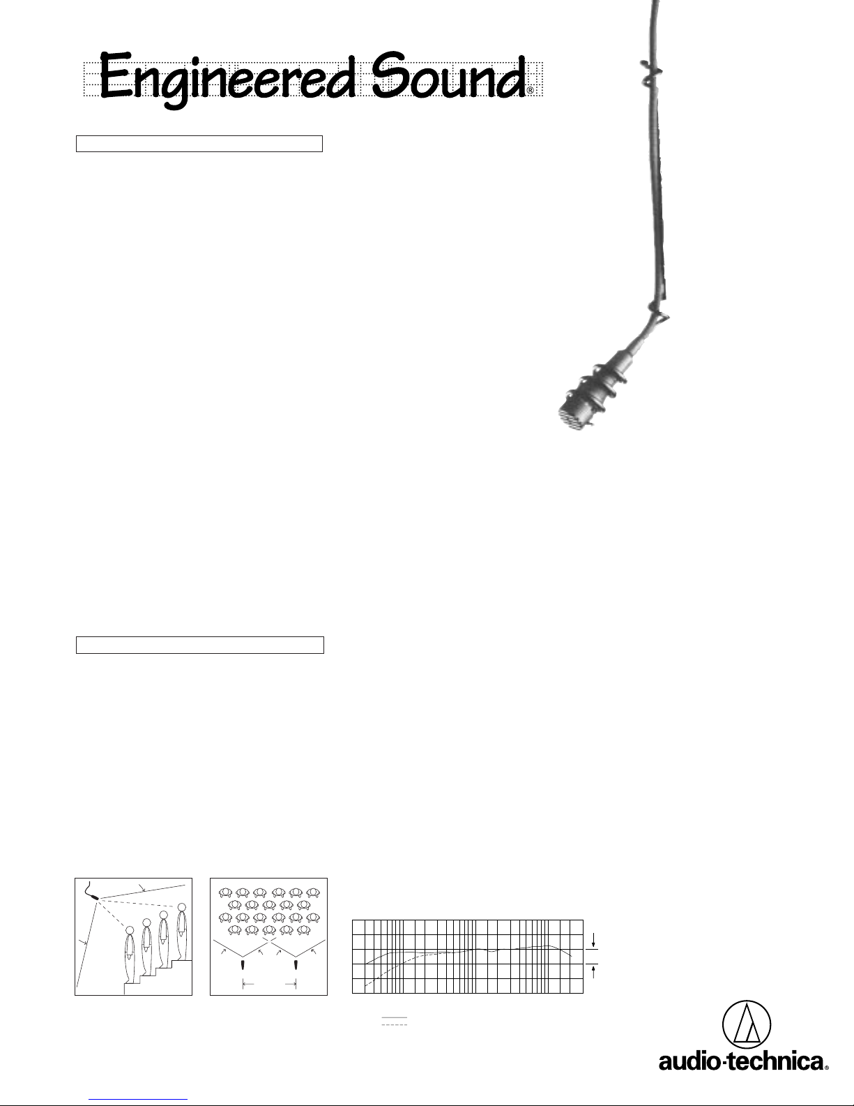
The AT933PM/C is a wide-range miniature
condenser microphone with a cardioid polar
pattern. It is designed for quality sound reinforcement and other demanding sound pickup applications. The AT933PM/C is furnished with a vinylcoated steel hanger that allows it to be positioned
inconspicuously over a choir, orchestra, stage,
etc., for very low-profile situations.
The microphone features a 50' (15.2 m)
permanently-attached miniature cable. The cable
may be cut to any length and connected to screw
terminals on the AT8534(A) wall/ceiling plate
power module provided. The AT8534(A) power
module features a white-finished standard
electrical cover plate for easy, secure installation.
It can be powered from any external 9V to 52V DC
phantom power supply. Output is low impedance
balanced.
Four additional interchangeable elements
are available to permit selection of angle of
acceptance from 90° to 360°.
Audio-Technica design engineers have
utilized the newest low-mass diaphragm technology
in the quest for superior performance. The
permanent charge is now on the fixed back plate,
rather than the moving element. With A-T fixedcharge “back plate” construction, a gold-vaporized
diaphragm just 2 microns thick (about .000079")
can be used. This considerably reduces moving
mass, thus improving frequency response and
transient response while reducing distortion.
The microphone is enclosed in a rugged
housing with a low-reflectance black finish. It is
also available in white as the AT933PMW/C, with
a white-finished microphone housing, cable and
steel hanger, for applications where the microphone must be hung against a light background.
Installation and Operation
The combination of small size and excellent
response makes the AT933PM/C ideal for
suspension over choirs, instrumental groups or
theater stages. A uniform 120° angle of acceptance provides well-balanced audio pickup. The
microphone should be located forward of the
front-most source, above the rear-most source,
and “aimed” between them (Fig. 1). Increasing the
height of the mic above the sources will tend to
equalize sound levels between them, but may
also increase background/reverberant sound
pickup. Whenever possible, the distance from the
mic to the rear-most pickup should be no more
than twice the distance to the front source, to
maintain front-to-rear balance (Fig. 1).
Width of pickup is approximately three times
the distance to the closest performer. If additional
mics are needed for wide sources, they should
not be closer together laterally than three times
the distance to the front source, to avoid phase
cancellation (Fig. 2).
To orient the microphone in the proper
direction, twist the housing slightly in its wire
holder (clockwise rotation moves the microphone
to the right; counterclockwise rotation moves
it to the left).
The provided foam windscreen simply slips
over the head of the microphone, effectively
reducing noise from wind or ventilation air currents.
The AT933PM/C offers a low-roll-off filter.
As supplied, the AT8534(A) power module is
wired for flat response. To enable the low-roll-off
filter, clip the jumper wire “ JW” on the AT8534(A)
circuit board. Low roll-off is useful in reducing
room rumble, low-frequency air movement
noise, and low-frequency vibration.
The AT8534(A) wall/ceiling plate
power module is designed to be
mounted in a standard single-gang
electrical box. For safety and best performance,
use the electrical box
only
for the AT8534(A); do
not include any AC power conductors. (Also route
the mic cable as far away from AC power cables
as possible.)
Feed the small cable from the mic through
the strain relief on the power module plate. Tie a
loose knot in the cable at the desired length and
push it down gently into the recess in the back of
the strain relief to secure the microphone. Cut
excess cable, strip the mic cable wires and attach
them to their respective input terminals. Screwterminal output connections of the AT8534(A) are
the same as those of an XLR-type plug: shield to
Terminal 1, balanced signal and phantom power
to Terminals 2 and 3. Output is phased so that
positive acoustic pressure produces positive
voltage at Terminal 2, in accordance with industry
convention.
shield to the box.
Do not connect the output cable
Double-check to make certain
that all input and output leads have no bare wires
or loose strands that could touch each other, the
circuit board or the electrical box. Then attach the
power module plate to the electrical box.
While a modern condenser microphone is
not unduly sensitive to the environment, temperature extremes can be harmful. Avoid leaving the
microphone in the open sun or in areas where
temperatures exceed 110° F (43° C) for long
periods of time. Extremely high humidity should
also be avoided.
Miniature
Condenser
Hanging
Microphone
with
Wall/Ceiling Plate
Power Module
LESS THAN 2 TIMES “X”
DISTANCE “X”
120°
ANGLE OF
ACCEPTANCE
Figure 1
MIC A MIC B
3 TIMES
DISTANCE “X”
Figure 2
Frequency Response (Typical)
120°120°
50
LEGEND
500
200100
Frequency in Hertz
12" or more on axis (flat)
Roll-off
2k
1k
10k
5k
10 dB
Response in dB
20k
Page 2
AT933PM/C
AT933PM/C Specifications
Element Fixed-charge back plate
†
permanently polarized condenser
Polar Pattern Cardioid (Unidirectional)
Frequency Response 40-20,000 Hz
Low-frequency Roll-off 150 Hz, 6 dB/octave
Open Circuit Sensitivity –33 dB (22.4 mV) re 1V at 1 Pa*
Impedance 200 ohms (1000 ohms without power module)
Maximum Input Sound Level 130 dB SPL, 1 kHz at 1% T.H.D.
Dynamic Range (Typical) 103 dB, 1 kHz at Max SPL
Signal-to-noise Ratio
1
67 dB, 1 kHz at 1 Pa*
Phantom Power Requirements 9-52V DC, 2 mA typical
Weight
Microphone 0.4 oz (10 grams)
Power Module 3.4 oz (96 grams)
Dimensions
Microphone 1.38" (35.0 mm) long, 0.48" (12.2 mm) head diameter
Power Module 2.80" (71. 0 mm) W x 4.55" (115.5 mm) H x 1.42" (36. 0 mm) D
Power Module Connectors Screw terminals
Cable 50' (15.2 m) long (permanently attached to microphone),
Accessories Furnished (AT933PM/C) AT8102 two-stage foam windscreen;
(AT933PMW/C) AT8102WH two-stage foam windscreen;
(Both) AT8534(A) power module;
Optional Interchangeable AT853H-ELE hypercardioid (100°)
Elements AT853ML-ELE MicroLine
0.13" (3.2 mm) diameter, 2-conductor, shielded cable
with pigtail output
AT8451 steel hanger
AT8451WH steel hanger
element adapter (for C/H/O/SC elements)
AT853O-ELE omnidirectional (360°)
AT853SC-ELE subcardioid (170°)
†In the interest of standards development, A.T.U.S. offers full details
on its test methods to other industry professionals on request.
* 1 Pascal = 10 dynes/cm2 = 10 microbars = 94 dB SPL
1
Typical, A-weighted, using Audio Precision System One.
(90°)
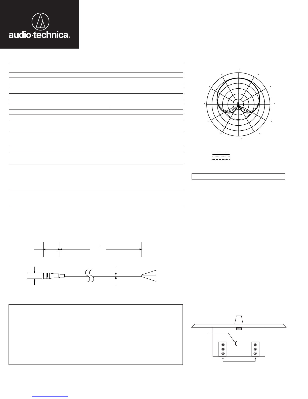
Dimensions
1.38"
35.0 mm
0.48"
12.2 mm
50
15.2 m
0.13"
3.2 mm
RED / RED
YEL / YEL
SHIELD
Polar Pattern
0
30
60
90
120
150
270
LEGEND
200 Hz
240
300
1 kHz
5 kHz
8 kHz
330
210
180
SCALE IS 5 DECIBELS PER DIVISION
Architects and Engineers Specifications
The microphone shall be a fixed-charge
condenser with a cardioid polar pattern and a
frequency response of 40 Hz to 20,000 Hz. It shall
be capable of accepting optional interchangeable
elements for additional polar patterns. It shall
operate from an external 9V to 52V DC phantom
power source. Nominal open-circuit output voltage
with the included wall/ceiling plate power module
shall be 22.4 mV at 1 kHz, 1 Pascal. Output shall
be low impedance balanced (200 ohms).
The microphone shall have a permanentlyattached 50' (15.2 m) miniature cable with a
pigtail output. The pigtail output shall connect
to screw terminals on the power module. Output
connections on the power module shall be screw
terminals.
The microphone shall be mountable in an
included steel hanger that allows permanent
overhead installation for pickup of dialogue,
orchestras and choirs. The microphone shall
be 1.38" (35.0 mm) long with a head diameter of
0.48" (12.2 mm). The microphone weight shall be
0.4 oz (10 grams) without cable. The microphone
case, cable and steel hanger shall be black [white].
The Audio-Technica AT933PM/C
[AT933PMW/C] is specified.
One-Year Limited Warranty
Audio-Technica microphones and accessories purchased in the U.S.A. are warranted for one year from date of
purchase by Audio-Technica U.S., Inc. (A.T.U.S.) to be free of defects in materials and workmanship. In event
of such defect, product will be repaired promptly without charge or, at our option, replaced with a new product
of equal or superior value if delivered to A.T.U.S. or an Authorized Service Center, prepaid, together with the
sales slip or other proof of purchase date.
excludes defects due to normal wear, abuse, shipping damage, or failure to use product in accordance with
instructions. This warranty is void in the event of unauthorized repair or modification.
For return approval and shipping information,
1221 Commerce Drive, Stow, Ohio 44224.
Except to the extent precluded by applicable state law,
incidental, or special damages; any warranty of merchantability or fitness for particular purpose
expires when this warranty expires.
This warranty gives you specific legal rights, and you may have other rights which vary from state to state.
Outside the U.S.A., please contact your local dealer for warranty details.
Prior approval from A.T.U.S. is required for return.
contact the Service Department, Audio-Technica U.S., Inc.,
A.T.U.S. will have no liability for any consequential,
Audio-Technica U.S., Inc., 1221 Commerce Drive, Stow, Ohio 44224
Audio-Technica Limited, Old Lane, Leeds LS11 8AG England
This warranty
Jumper wire
YEL / YEL
RED / RED
SHIELD
INPUT
Power Module
YL
RD
SH
© 1996 Audio-Technica U.S., Inc. Printed in U.S.A.
JW
IN OUT
Terminal screws
Form No. 0309-9507-00-B/W P50887
3
2
1
AUDIO
AUDIO
SHIELD
OUTPUT
–
+
 Loading...