

Page 1

Professional VHF Wireless Systems
ATW-D12a Diversity Antenna Distribution System
ATW-A10 Ground Plane Antenna System
Installation and Operation
Page 2
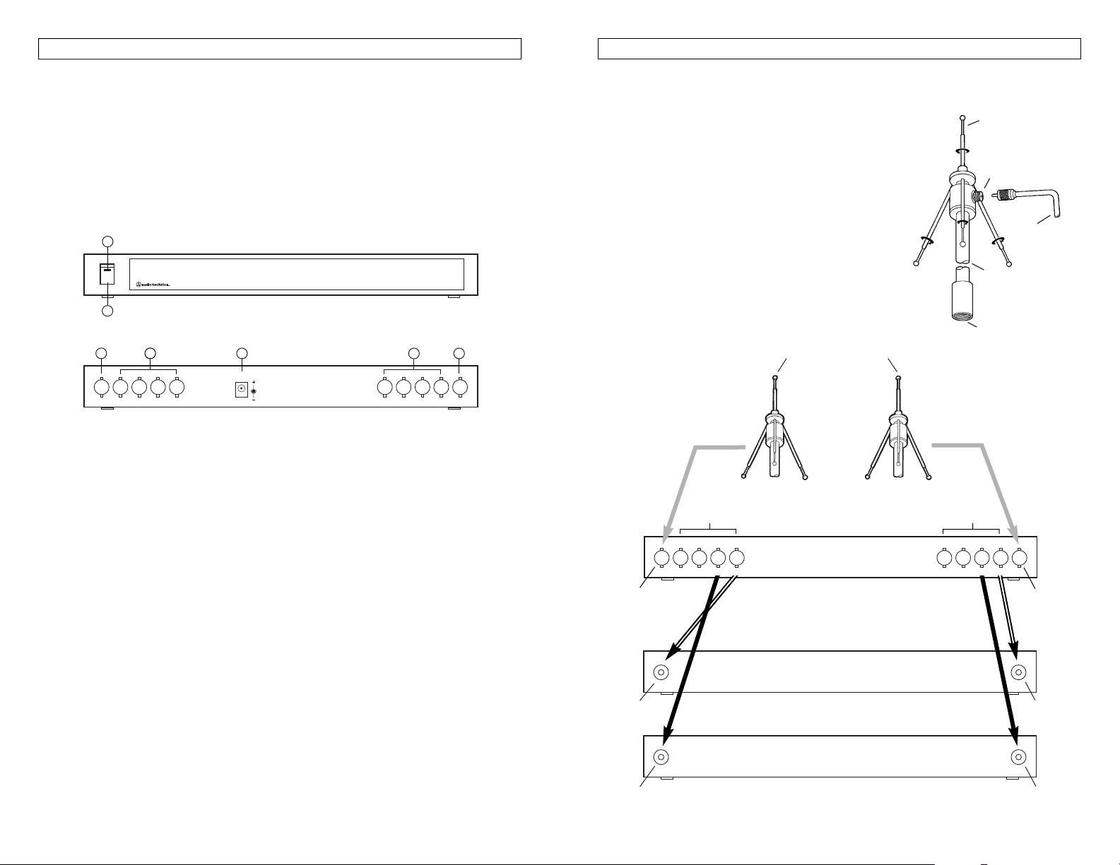
ATW-A10 Ground Plane Antenna System
The ATW-A10 consists of two base assemblies and eight
antenna rods. To assemble, screw four antenna rods into
each base assembly as shown in Figure 2.
The
5
/8"-27 threads in the end of the base assembly will mate
with any standard microphone stand or
5
/8"-27 stand adapter.
Connect the ATW-A10 ground plane antennas to the antenna
inputs of either a wireless receiver or the ATW-D12a antenna
distribution system. Use RG58 cable for cable lengths of up
to 25'. For cable lengths greater than 25', RG8 (low loss)
RF cable is recommended. RG8 cable lengths over 100'
may cause significant signal loss.
For best performance, the two ground plane antennas should
be at least 3' apart. Some experimentation with positioning
may be required. For optimum operation, at least one
antenna should remain within sight of the wireless
microphone transmitter at all times.
Figure 2
Figure 3. System Configuration
ATW-A10 Ground Plane Antenna System
ATW-A10 Ground Plane
Antenna System
The ATW-D12a feeds up to 4 diversity wireless receivers
ATW-D12a Diversity Antenna
Distribution System
Diversity Wireless Receiver #1
Diversity Wireless Receiver #2
Antenna B Input
B Outputs
A Outputs
Base Assembly
Antenna Rod (4 pcs.)
5
/8"-27 Threads
PL259 Jack
Antenna
cable
(not included)
Antenna A Input
Antenna
cables not
included
Antenna B Input Antenna A Input
Antenna B Input Antenna A Input
4321
4321
ATW-D12a Installation and Operation
The ATW-D12a is a VHF band antenna distribution system for use with diversity wireless receivers.
It provides isolated antenna feeds for up to four VHF diversity wireless receivers.
Function The ATW-D12a has two BNC antenna inputs, one for each antenna of a diversity
wireless system. Each channel provides amplification to restore the loss due to signal-splitting.
Each nominally unity-gain antenna input/amplifier section has four isolated BNC outputs.
The ATW-D12a is supplied with two extendible antennas, rack adapters for use in standard 19"
racks, two BNC (male) to PL259 (female) adapters, and eight 2.6' BNC to PL259 coaxial
interconnect cables.
Reference
1. Power Switch
2. Power Indicator
3. Channel B Antenna Input Jack (BNC)
4. Channel B Distribution System Output Jacks (BNC)
5.+12V DC Input Jack
6. Channel A Distribution System Output Jacks (BNC)
7. Channel A Antenna Input Jack (BNC)
ATW-D12a System Configuration The ATW-D12a is designed to work with the included VHF
antennas or remote antennas, such as the ATW-A10 ground plane diversity antenna system.
When using remote antennas, RG58 cables of up to 25' may be used with little loss. If antenna
cable lengths are over 25', RG8 cable is recommended.
The ATW-A10 antennas should be mounted in a clear area away from metal obstructions and
spaced at least 3' apart. They may be mounted directly on a microphone stand.
Unused outputs of the ATW-D12a antenna distribution system do not require termination.
ATW-D12a Specifications Accessories Included
Input impedance 50 ohms 1 - AC adapter
Output impedance 50 ohms 2 - Extendible VHF antennas
Usable frequency range 150 MHz-250 MHz 2 - BNC (male) to PL259 (female) adapters
Nominal amplifier gain 0 dB ± 3 dB 8 - Interconnect cables (BNC to PL259)
AC adapter power input 120V AC, 60 Hz, 12 W 1 - Rack-mount kit
AC adapter rated output 12V DC, 500 mA
Dimensions 16.54" W x 7.80" D x 1.75" H
Weight (less accessories) 3 lb 7 oz
Figure 1
ATW-D12a front view
ATW-D12a rear view
ATW-D12a
DIVERSITY VHF ANTENNA DISTRIBUTION SYSTEM
DC IN
12V-15V
4321
4321
4
1
2
5 6 7
3
Page 3

One-Year Limited Warranty
Audio-Technica brand products purchased in the U.S.A. are warranted for one year from date of purchase
by Audio-Technica U.S., Inc. (A.T.U.S.) to be free of defects in materials and workmanship. In event of such
defect, product will be repaired promptly without charge or, at our option, replaced with a new product of
equal or superior value if delivered to A.T.U.S. or an Authorized Service Center, prepaid, together with the
sales slip or other proof of purchase date.
Prior approval from A.T.U.S. is required for return.
This warranty excludes defects due to normal wear, abuse, shipping damage, or failure to use product in accordance
with the instructions. This warranty is void in the event of unauthorized repair or modification, or removal
or defacing of the product labeling.
For return approval and shipping information,
contact the Service Dept., Audio-Technica U.S., Inc.,
1221 Commerce Drive, Stow, Ohio 44224.
Except to the extent precluded by applicable state law,
A.T.U.S. will have no liability for any consequential,
incidental, or special damages; any warranty of merchantability or fitness for particular purpose
expires when this warranty expires.
This warranty gives you specific legal rights, and you may have other rights which vary from state to state.
Outside the U.S.A., please contact your local dealer for warranty details.
Audio-Technica U.S., Inc., 1221 Commerce Drive, Stow, Ohio 44224 330/686-2600
Audio-Technica Limited, Old Lane, Leeds LS11 8AG England 0113 277 1441
P50866- 01-B/W ©1997 Audio-Technica U.S., Inc. Printed in Taiwan
 Loading...