

Audio Technica ATW-901a/G, ATW-901a/H, ATW-901a/L, ATW-902a Installation And Operation Manual
@audio-technica
System 9
VHF
Wireless System
Installation and Operation
0
0000
RF
~
0
PEAK
ATW-901a/G
Gu
itar System
ATW-901a/H
Headworn Microphone System
ATW-901a/L
Lavalier Microphone System
ATW-902a
Handheld Microphone System
@audio-technica
2
System 9 Installation
This device complies with part
to
the condition that this device does
A copy
of
the
www.audio-technica.com.
This device
standard(s) .. Operation is subject
this device may
interference, including interference that may cause undesired
any
operation
Le present appareil
applicables aux appareils radio exernptsdelicence.••L'exploitation
autorisee aux deux conditions s\}ivahtes :
produire
bro~;~iiiE@3
d'en
,g:>fl1prornettre·
:-'":">:
"'-".""
CAUTION!
·
Gbvei.
~~t:\ijce~lili
Th~
eire;"
adjusted
regulations,•
willvo~
declaration
complies
not
of
the
device.
de
brouillage, ed2ll'1Jtilisateur
•'t!idiQelectriquesubi,
" ' :··.
':<'''
." ··":'-'":'-; '-," '-:':'';
Electrical shocl:: can result
Refer
servipingto
•
lf<!J~s
~
jn~ide.Po
-
e
tti~
optimum
Do
riotattef'nptto.QPen
'Ule
warranty.
and
Operation
15
of
the
FCC
Rules. Operation is subject
not
cause harmful interference.
of
conformity can be found on the internet at
with
Industry Canada license-exemptRSS
to
the
following
cause interference, and
est
conforme aux
li!}
.. fo'nctionhernent.
';::: ' " '
'-·""."'--
qualified service personnel.
nc>t
..
· :: , ,'
,"
reeeilJ~r
perlol'rnal'lc~
and
may
CNRd'lndustrie
'
m~me•si
" . '
""···
•-•-• - -- ··
from
expose
::
.. ' ..
··
: .· .
and
tnmsmitter
and
the
cause
improper
de
le ()rouillage·•est·susceptible
to
compliance
. r'eceiver.
two
(2)
this device
(l
l
I'
appareilhe
..
l'appareH
--.-~,
removal
rain
or
moisture.
'''
hav~
or
operation. . .
c,onditions:
Canada
doifaccepter
of
No
.
beeri precisely
with
transrni
must
do
it pas
the receiver
user-
tedera.l
tter_J(l
(1
l
accept
est
tout
....
.
do
to
Because System 9 packaging is designed
of
the system, some compartments in the carton may be intentionally
empty.
left
The
A1W-R900a receiver includes a switching power supply that
to
automatically adapts
The versatile
a high-impedance input for
with
microphones. The
unidirectional dynamic microphone element.
Both
and have
A1W-T901 a UniPak body-pack transmitter has both
bias connection for use
the
body-pack and handheld transmitters use internal AA batteries
Power/Mute switches
changes in mains voltage.
instruments, and a low-impedance input
with dynamic and electret condenser
A1W-T902a handheld transmitter features a
and
hold all versions
inputTrim (level) adjustments.
Receiver Installation
Location
For best operation the receiver should be
(1
ground and at least 3'
minimize reflections. Keep the receiver antennas away from noise
sources such
lights. as
systems, position receivers at least 3'
transmitters at least 6'
so
maximum
as
well as
RF
performance.
m) away from a wall or metal surface
digital equipment, motors, automobiles and neon
away from large metal objects
(2
m) from the receivers
at
least 3'
In
multi-channel
(1
m) apart and keep operating
to
help assure
(1
m)
above the
to
Noti~~·
.to•
devlcSs: ·.···.··
illciilli4ualll
Arw source
functioning
low-power transmitters
to
cause cMficulty, especially
However, since a "body-pacl::"•
the .
pockefVo~here
Note
transmitting source
medical-device proviqer.
prOblems
Thank you for choosing
system.
have chosen our products because
reliability. This wireless microphone system is the successful result
years
Audio-Technica's Sys
system designed
easy setup and clear, natural sound quality. Featuring stackable,
contemporary styling,
guitar,
compatible user-switchable channels in one
frequencies
Each
and either a body-pack transmitter or a handheld microphone/transmitter.
A1W-
-packag
pre
headworn microphone
All A-T Wireless Essentials® microphones and
are pre-terminated for use with any
of
of
the
body,we
suggest·attachil'1g it.
it
~17otpatany
:
With:the'.useofthis
You
have joined thousands
of
design and manufacturing experienc
lavalier and body-pack configurations. The sys
(169.505, 170 245, 171.045, and
System 9 professional
901a
UniPak®body-pack transmitter systems include models
ed
with
Wifh·.im,plinted
cardiac.
· ·· . · .•..•
RF
(radio frequency). energy
implanted device.
(less
than
Q.OEiwatts
if
t hey ate !it)E!ast a ·
mic
at
may be
immed · ··
medicai-d ...
is
turned oft Pleasec()otact yourphvsician
if
an
tem
to
provide rock-solid performance along
System 9
either an AT-GCW guitar cable
(JH).
e!Y
..
··
..
·
i;lisruptrori
• you
ha¥e·a,Yfql.j~tiqns
•
oraf'lv
Audio-Technica professional
9 is a four-channel frequency-agile wireless
is
VHF
wireless system includes a receiver
or a lavalier
mayinterfere
All
wireless microphones:
output
transmitter typically
the belt,
rather
ad)~.nHo
vYiH
•
!lt~I'RF
of
of
available in handheld, headworn.
A1W-901
.
equipment.
other
satisfied customers w ho
their quality, performance and
e.
of
171
mic
(JL)
cables, available separately,
system.
pat:emakfns
] Whith ·
.ti'lal'l.ina
.ithep:ie¢llcal
p~as¢\t\!hen
•• or':
tem
four available VHF
.905 MHz
(JG). a PRO 8HE
for particular applications.
or,lf!Cp
,,,,
.•
.•
:,.
•vyith
normal
h~ve
··
li~IY
..
. .
is•pl~c~d
experienc.e•.any
wir
!
~gairist
shirt
device.
.
ihe
RP
or
·
eless
with
offers four
).
cW
•
·
of
Output
.··
·.'
Connections
There are
unbalanced. Use shielded audio cable for
receiver and the mixer.
ca
housing
connect
panel
ble
two
audio outputs on the back panel: balanced and
from
to
1
the
to
the mixer. If the input
ab
le from the balanced XLR-type audio
a c
the mixer.
If the input of the mixer
/4 unbalanced audio output on the back
of
the mixer
Power Connection
Connect the
power
hook on
an
by
120 Volt 60 Hz
(Note that the receiver has no power
energized whenever the
the
AC
sys
tem
DC
plug on the included
inp
ut
on the back
the
back
accident
al
AC
outlet. Unplug the power supply
is not in use - both for safety, and
of
the
of
the receiver, to keep the plug from being detached
tug
on
pow
er outlet.
receiver. Secure
the cord. Then plug the adapter into a standard
power
adapter is connected and plugged into
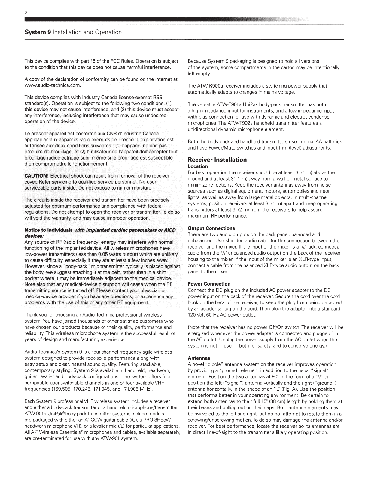
Antennas
A novel
"dipo
le" antenna system on the receiver improves operation
by providing a
element. Position the
position the left
antenna horizontally,
that performs better in your operating environment.
extend both antennas
their bases and pulling o
be swiveled to the
screwing/unsc
receiver. For best
in direct line-of-sight
"ground"
re
element in addition
two
antenn
as
at 90° in the form
("signal ") antenna vertically and
in
the shape
to
the1r
ut
left and right, but
wing motion.
performance, locate the receiver so
to
the transmitter's likely operating position.
of
an
full 15' (38 em) length by holding
on their caps. Both antenna elements may
do
To
do so may damage the antenna and/or
the
connection between the
1
is
a
/4 jack, connect a
of the
receiver
is
an
XLR
-type input,
out
put on the back
AC
power adapter
the
Off/On switch. The receiver will be
from
the
to
conserve ener
to
the usual "signal"
"L.:'
(Fig. A). Use the position
not atte
mpt
to the
cord over the cord
AC
outlet
when the
gy.)
of
a "V;' or
the
right ("ground")
Be
certain
to
rotate
them
its an
tennas are
DC
to
them
at
in a
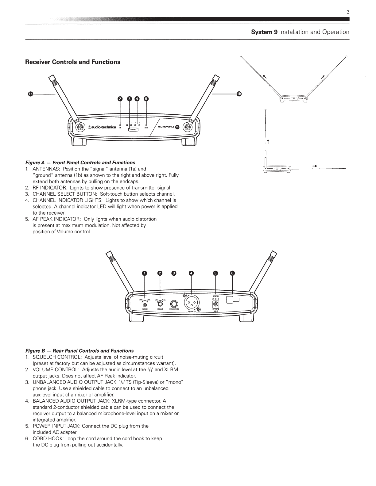
Receiver Controls and Functions
3
System 9 Installation and Operation
0--------
@audio-technica
Figure A - Front Panel Controls
1.
ANTENNAS: Position the "signal" antenna
"ground"
extend both antennas by pulling on the endcaps.
2.
RF
3. CHANNEL SELECT BUTION: Soft-touch button selects channel.
4. CHANNEL INDICATOR
selected. A channel indicator
to
5.
AF
is
position
antenna
INDICATOR: Lights to
the receiver.
PEAK
INDICATOR: Only light s
present at maximum modulation.
of
(1
b)
Volume control.
as
shown
show
LIGHTS
and
Functions
(1a)
to
the right and above right. Fully
presence
Lights
LED
will light when power
when
Not
and
of
transmitter signal.
to
show which channel is
audio distortion
affected by
is
applied
---~
t
Figure 8 -
1.
SQUELCH CONTROL: Adjusts level
(preset at fac
2.
VOLUME CONTROL: Adjusts the audio level at
output jacks. Does
UNBALANCED AUDIO OUTPUT JACK:
3.
phone jack. Use a shield
aux-level
4. BALANCED AUDIO OUTPUT JACK: XLRM-type conne ctor. A
standard 2-conduc
receiver output
integrated
5. POW
included
CORD HOO
6.
the
Rear
Panel Controls
tory
but can be adjusted as circumsta nces warrant).
not
input
of
a mixer or amplifier.
tor
shielded cable can be used
to
a balanced microphone-level input on a mixer or
amplifier.
ER
INPUT JACK: Connect the
AC
adapter.
K:
Loop the co
DC
plug from pulling
affect
ed cable
rd
out
and
Functions
of
AF
Peak
indicator.
to
conne
DC
plug from the
around
the cord
accidentally.
noise-muting circuit
1
/4
TS
ct
the '/4 and XLRM
(Tip-Sleeve)
to
an
unbalanced
to
connect
hook
to
keep
or
"mono"
the
 Loading...