

Audio Technica ATW-7373, ATW-7376, ATW-7375 Installation And Operation Manual

7000 Series Professional
UHF Wireless Systems
ATW-7373
Handheld Condenser Microphone System
ATW-7375
UniPak™Transmitter System
ATW-7376
Handheld Dynamic Microphone System
Installation and Operation
To prevent electric shock, do not remove the
cover. There are no user-serviceable parts
inside. Internal adjustments are for qualified
professionals only. Refer all servicing to
qualified service personnel.
Pour prévenir un choc électrique, ne pas ouvrir
le couvercle. Il n’y aucune pièces de rechanges
à l’intérieur. Tout ajustement interne doit être
fait par une personne qualifié seulement.
Référez tout réparation au personnel qualifié.
2
Professional UHF Wireless Systems
Installation and Operation
CAUTION! The circuits inside the receiver and transmitter have
been precisely adjusted for optimum performance and
compliance with federal regulations. Do not attempt to open the
receiver or transmitter. To do so will void the warranty, and may
cause improper operation.
Individuals with implanted cardiac pacemakers or AICD
devices: Please see notice on back cover.
This device complies with part 15 of the FCC Rules. Operation is
subject to the condition that this device does not cause harmful
interference.
This device complies with INDUSTRY CANADA R.S.S. 210, en
conformité avec IC: RSS-210/CNR210. Operation is subject to
the following conditions: 1) This device may not cause harmful
interference and 2) this device must accept any interference
received, including interference which may cause undesired
operation.
Introduction
Thank you for choosing an Audio-Technica professional
wireless system. You have joined thousands of other satisfied
customers who have chosen our products because of their
quality, performance and reliability. This Audio-Technica
wireless microphone system is the successful result of years
of design and manufacturing experience.
This professional wireless system provides a choice of 100
PLL-synthesized UHF frequencies. Each system includes a
receiver and either a body-pack or handheld transmitter.
The receiver features true diversity reception. Two antennas
feed two completely independent RF sections on the same
frequency; automatic logic circuitry continuously compares
and selects the superior received signal, providing better
sound quality and reducing the possibility of interference and
dropouts. The receiver is half-width for a standard 19" (1U)
rack mount. Two receivers (on different frequencies) can be
mounted side by side, using an AT8628 joining plate kit.
The versatile ATW-T75 UniPak
™
body-pack transmitter has
both low- and high-impedance inputs plus a bias connection,
for use with dynamic and electret condenser microphones, as
well as Hi-Z instrument pickups. The ATW-T73 handheld condenser microphone/transmitter features the same element as
the legendary AT4033 studio condenser microphone. The
ATW-T76 handheld dynamic microphone/transmitter features
a Hi-ENERGY
®
neodymium dynamic element. The UniPak and
handheld transmitters use internal 9-volt batteries and have
Off/Standby/On switches and battery condition indicators.
Please note that in multiple-system applications there must
be a transmitter-receiver combination set to a
separate
frequency for each input desired (only one transmitter for each
receiver). Because some of the wireless frequencies are in or
near UHF TV frequencies, only certain wireless frequencies
are useable in a particular geographic area. Also, only certain
of the available operating frequencies may be used together.
(Suggestions for multiple-system frequency grouping will be
found on page 7.)
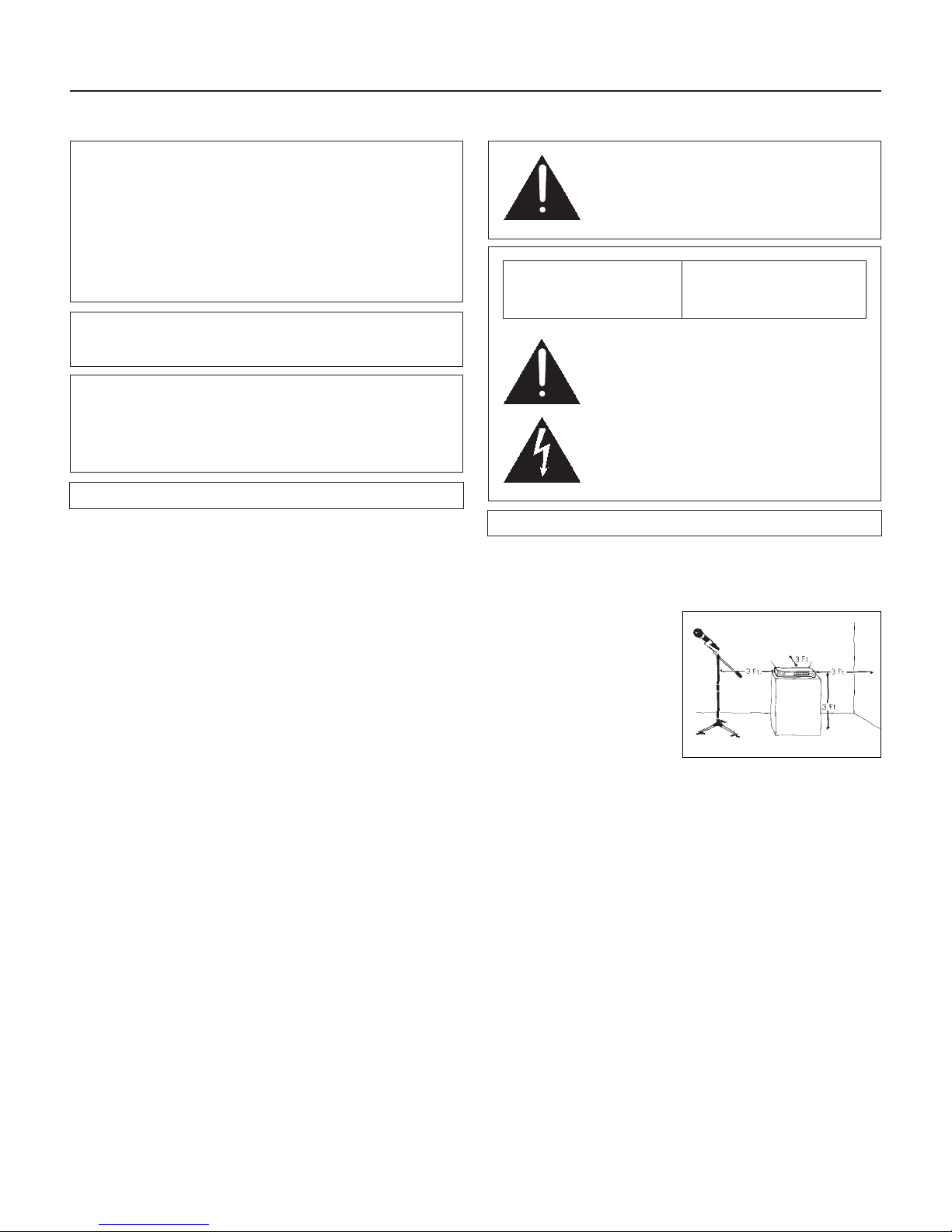
Receiver Installation
Location
For best operation the receiver should be at least 3 ft. above
the ground and at least 3 ft. away from a wall or metal surface
to minimize reflections. The
transmitter should be at
least 3 ft. from the receiver,
as shown in Figure A.
Keep antennas away from
noise sources such as digital
equipment, motors,
automobiles and neon
lights, as well as large
metal objects.
Output Connections
There are two audio outputs on the back of the receiver:
balanced (15.8 mV) and unbalanced (50 mV) . Use shielded
audio cable for the connection between the receiver and the
mixer. If the input of the mixer is a
1
⁄4" jack, connect a cable
from the
1
⁄4" unbalanced audio output on the back of the
receiver to the mixer. If the input of the mixer is an XLR-type
input, connect a cable from the balanced XLR-type audio
output on the back of the receiver to the mixer.
The two isolated audio outputs permit simultaneous feeds
to both unbalanced and balanced inputs. For example, both
a guitar amp and a mixer can be driven by the receiver.
Antennas
Attach the antennas to the antenna input jacks. The antennas
are normally positioned in the shape of a “V” (45° from
vertical) for best reception.
Power Connections
Connect to a standard 120 volt 60 Hz AC power outlet. If
there is no AC power available, the back panel is equipped
with a jack for an external 12-18 volt DC source. The jack
takes a standard 2.5 mm I.D. coaxial DC power plug, center
negative
. Power from the DC input jack is switched by the
front-panel Power switch.
Fig. A
AVIS
RISQUE DE CHOC ÉLECTRIQUE
NE PAS OUVRIR
CAUTION
RISK OF ELECTRIC SHOCK
DO NOT OPEN
Warning: To prevent fire or shock hazard, do
not expose this appliance to rain or moisture.
Attention: Pour prévenir feu ou choc
électrique, ne pas exposé l’appareil à la pluie
ou à l’humidité.
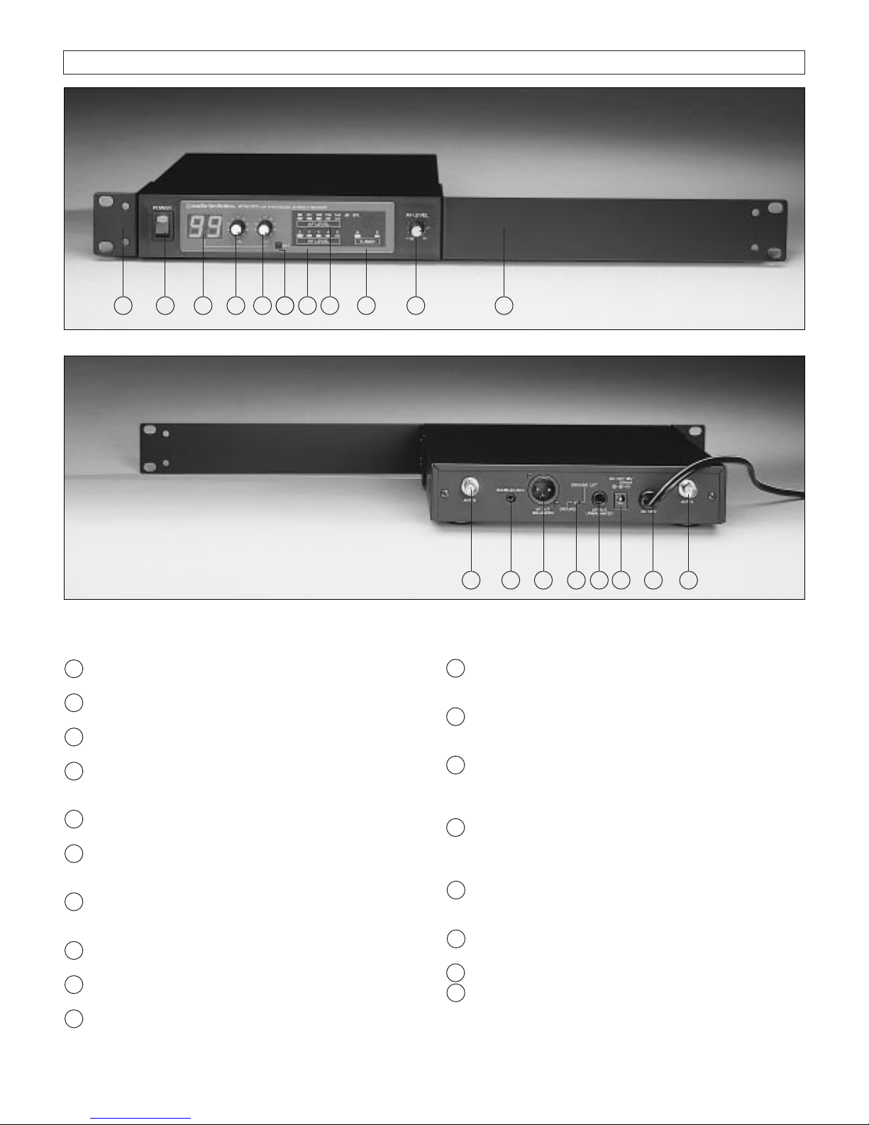
Rear Panel Controls and Functions (Fig. C)
11 TUNER “B” ANTENNA JACK: Antenna connector for
tuner “B.” Attach the antenna directly, or extend it
with an antenna cable.
12 SQUELCH CONTROL: Adjusts level of noise-muting
circuit (preset at factory but can be adjusted as
circumstances warrant).
13 BALANCED AUDIO OUTPUT JACK: XLRM-type connec-
tor. A standard 2-conductor shielded cable can be used
to connect the receiver output to a balanced microphone
level input on a mixer.
14 GROUND LIFT SWITCH: Disconnects the ground pin
of the balanced output (13) from ground. Normally, the
switch should be to the left (ground connected). If hum
caused by a ground loop occurs, slide switch to the right.
15 UNBALANCED AUDIO OUTPUT JACK:
1
⁄4" phone jack.
Can be connected to an unbalanced aux-level input of a
mixer or tape recorder.
16 DC POWER INPUT: For an external 12-18V DC source
(requires 350 mA). Center pin of jack is
negative
.
17 AC POWER: Power cord for 120V AC power input.
18 TUNER “A” ANTENNA JACK: Antenna connector for
tuner “A.” Attach the antenna directly, or extend it
with an antenna cable.
3
Receiver Controls And Functions
Fig. B Receiver Front Panel
Fig. C Receiver Rear Panel
5431 10
171615
1311
18
62
12
14
7 810 9
Front Panel Controls and Functions (Fig. B)
1 POWER SWITCH/INDICATOR: Press switch on, and
the “power” indicator will light.
2 CHANNEL NUMBER DISPLAY: Indicates the current
channel setting.
3 X10 CHANNEL SELECTOR SWITCH: Selects the number
shown in the left column of the Channel Number Display.
4 X1 CHANNEL SELECTOR SWITCH: Selects the number
shown in the right column of the Channel Number
Display.
5 CHANNEL SET BUTTON: Press this button to input the
channel shown in the Channel Number Display.
6 RF SIGNAL LEVEL INDICATOR: Indicates the
strength of the RF signal received from the transmitter.
The LEDs will light up from left to right.
7 AF LEVEL INDICATOR: Indicates the audio modulation
level of the received signal. (Not affected by the
setting of the AF Level control.)
8 TUNER OPERATION INDICATOR: Indicates which
tuner has the better reception and is in operation.
9 AF LEVEL CONTROL: Adjusts the level at both audio
output jacks.
10 MOUNTING ADAPTERS: For mounting the receiver
in any standard 19" rack. Attach to receiver with
screws supplied. (Use optional AT8628 joining plate
kit to mount two receivers side-by-side.)
 Loading...