

Audio Technica ATW-1451, ATW-1452 Installation And Operation Manual

1400 Series Professional
UHF Wireless Systems
ATW-1451
UniPak™Transmitter System
ATW-1452
Handheld Dynamic Microphone System
Installation and Operation
Individuals with implanted cardiac pacemakers or
AICD devices: Please see notice on back cover.
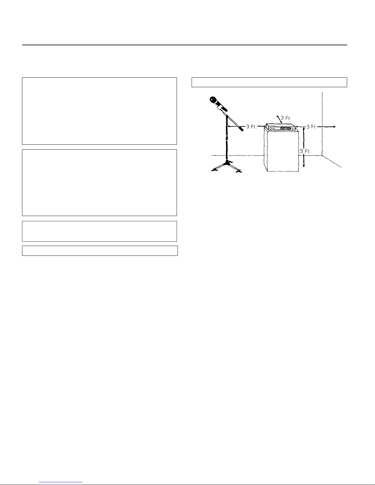
Location
For best operation the receiver should be at least 3 ft. above
the ground and at least 3 ft. away from a wall or metal surface
to minimize reflections. The transmitter should also be at least
3 ft. away from the receiver, as shown in Figure A.
Keep antennas away from noise sources such as motors,
automobiles, and neon lights, as well as large metal objects.
Output Connections
There are two audio outputs on the back of the receiver:
balanced (160 mV) and unbalanced (280 mV). Use shielded
audio cable for the connection between the receiver and the
mixer. If the input of the mixer is a
1
/4" jack, connect a cable
from the
1
/4" unbalanced audio output on the back of the receiver to the mixer. If the input of the mixer is an XLR-type input,
connect a cable from the balanced XLR-type audio output on
the back of the receiver to the mixer.
The two isolated audio outputs permit simultaneous feeds to
both unbalanced and balanced inputs. For example, both a
guitar amp and a mixer can be driven by the receiver.
Antennas
Attach the antennas to the antenna input jacks.
Power Connections
Connect the included AD1205A AC adapter to the DC power
input on the back of the receiver. Then plug the adapter into
a standard 120 volt 60 Hz AC power outlet.
Thank you for choosing an Audio-Technica professional wireless
system. You have joined thousands of other satisfied customers
who have chosen our products because of their quality, performance and reliability. This Audio-Technica wireless microphone
system is the successful result of years of design and
manufacturing experience.
This professional wireless system includes a receiver and
either a body-pack or a handheld transmitter on a specific
crystal- controlled frequency.
The receiver features true diversity reception. Two antennas
feed two completely independent RF sections on the same
frequency; automatic logic circuitry continuously compares and
selects the superior received signal, providing better sound
quality and reducing the possibility of interference and dropouts.
The receiver is half-width for a standard 19" (1U) rack mount.
Two receivers (on different frequencies) can be mounted side
by side, using an AT8628 joining plate kit.
The versatile UniPak
™
body-pack transmitter has both low- and
high-impedance inputs plus a bias connection, for use with
dynamic and electret condenser microphones, as well as Hi-Z
instrument pickups. Both the handheld and UniPak transmitters
use internal 9-volt batteries and have Off/Standby/On switches,
battery condition indicators, and battery-save switches.
Please note that in multiple-system applications there must be
a transmitter-receiver combination on a
separate
frequency for
each input desired (only one transmitter for each receiver).
Operating frequency information will be found on page 7.
Professional UHF Wireless Systems
Installation and Operation
Receiver Installation
Introduction
Fig. A Receiver Location
2
CAUTION! Electrical shock can result from removal of
the receiver cover. Refer servicing to qualified service
personnel. No user-serviceable parts inside. Do not
expose to rain or moisture.
The circuits inside the receiver and transmitter have been
precisely adjusted for optimum performance and compliance with federal regulations. Do not attempt to open the
receiver or transmitter. To do so will void the warranty,
and may cause improper operation.
This device complies with part 15 of the FCC Rules.
Operation is subject to the condition that this device does
not cause harmful interference.
This device complies with INDUSTRY CANADA R.S.S.
210,en conformité avec IC: RSS-210/CNR210. Operation
is subject to the following conditions: 1) This device may
not cause harmful interference and 2) this device must
accept any interference received, including interference
which may cause undesired operation.
POWER
MIN MAX
AF LEVEL
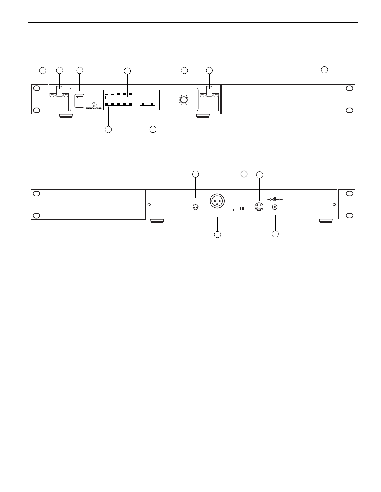
Front Panel Controls and Functions (Fig. B)
1. TUNER “A” ANTENNA JACK: Antenna connector for
tuner “A.” Attach the antenna directly, or extend it with
an antenna cable.
2. POWER SWITCH/INDICATOR: Press switch on, and the
“Power” indicator will light.
3. RF SIGNAL LEVEL INDICATOR: Indicates the strength of
the RF signal received from the transmitter. The LEDs
will light up from left to right.
4. AF LEVEL INDICATOR: Indicates the audio modulation
level of the received signal. (Not affected by the setting
of the AF Level control.)
5. TUNER OPERATION INDICATOR: Indicates which tuner
has the better reception and is in operation.
6. AF LEVEL CONTROL: Adjusts the level at both audio
output jacks.
7. TUNER “B” ANTENNA JACK: Antenna connector for
tuner “B.” Attach the antenna directly, or extend it with
an antenna cable.
8. MOUNTING ADAPTERS: For mounting the receiver in any
standard 19" rack. Attach to receiver with screws supplied.
Rear Panel Controls and Functions (Fig. C)
9. SQUELCH CONTROL: Adjusts level of noise-muting circuit
(preset at factory but can be adjusted as circumstances
warrant).
10. BALANCED AUDIO OUTPUT JACK: XLRM-type connector.
A standard 2-conductor shielded cable can be used to
connect the receiver output to a balanced aux-level input
on a mixer.
11. GROUND LIFT SWITCH: Disconnects the ground pin of
the balanced output (10) from ground. Normally, the switch
should be to the left (ground connected). If hum caused by
a ground loop occurs, slide switch to the right.
12. UNBALANCED AUDIO OUTPUT JACK:
1
/4" phone jack.
Can be connected to an unbalanced aux-level input of
a mixer or tape recorder.
13. DC POWER INPUT: For the provided AD1205A AC adapter,
or other 12-18V DC source. (Receiver requires 500 mA.)
Receiver Controls and Functions
Fig. B Receiver Front Panel
Fig. C Receiver Rear Panel
AF OUT
BALANCED
AF OUT
UNBALANCED
SQUELCH ADJ.
GROUND LIFT
GROUND
DC 12V~18V
500 mA
3
2
1
8
9
10
11
3
6
8
UHF
DIVERSITY
RECEIVER
AF LEVEL
80 92 106 126 140 dB SPL
1 2 3 4 5
A B
RF LEVEL TUNER
4
7
5
12
13
ANT. A
ANT. B
 Loading...