

Audio-Technica ATW-1301 Datasheet
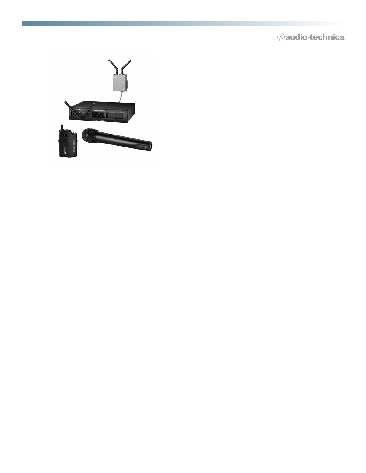
System 10 PRO
Rack-Mount Digital Wireless System
Features
• Digital 24-bit/48 kHz wireless operation for ultimate sound quality
and dependable performance
• Operates in the 2.4 GHz range – completely free from TV interference
• Receiver units can be docked in the chassis or mounted remotely (up
to 328 feet away) via UTP cable for added versatility
• Up to ve chassis (ten receiver units) can be linked and used
simultaneously
• Each receiver unit can be paired with up to 10 transmitters,
allowing users to instantly switch between different transmitter
congurations
• Chassis’ System ID Display shows RF signal level, system ID,
transmitter battery level, and system link status
• Automatic frequency selection for seamless, interference-free
operation
• Extremely easy operation with instantaneous channel selection,
sync, and setup
• Three levels of diversity assurance: frequency, time & space
• Ground-lift switch helps eliminate audible hum caused by ground
loops
Description
System 10 PRO Rack-Mount brings new versatility to the System 10
family of 2.4 GHz digital wireless products. With remote-mountable
receiver units and the simultaneous use of up to 10 channels, System 10
PRO combines innovation with rock-solid performance, easy setup and
clear, natural sound quality.
The ATW-RC13 half-rack receiver chassis features two receiver unit docks,
each designed to house an ATW-RU13 receiver unit. Two RJ45 connectors
on the rear of the chassis allow each receiver unit to be released from the
chassis and mounted up to 100 m (328 ft.) away via standard UTP cable.
The chassis is also equipped with IN/OUT RJ12 connectors that can be
used to link the chassis to another chassis (up to ve chassis – 10 receiver
units – can be linked together) allowing for simultaneous use of all receivers
and increased stability of a multichannel system. The front of the chassis
is equipped with a System ID Display that indicates the RF signal strength,
System ID number and battery level for the transmitter currently engaged
with each receiver unit. The display also shows if the chassis is currently
linked to another chassis. Additionally, the chassis features an AF level
control, ground lift switch, unbalanced ¼" output connection and balanced
XLRM-type output connection for each receiver unit.
The ATW-RU13 receiver unit features two detachable antennas that screw
onto the face of the unit via SMA connectors. The rear of the unit is equipped
with a ¼"-20 thread socket for mounting the receiver unit remotely to a tripod
or other device with a ¼" screw. An RJ45 connector, also on the rear of the
unit, allows a remotely mounted receiver unit to be connected to the chassis
with UTP cable. An LED status indicator, located between the mounting
wireless systems
socket and the RJ45 connector, blinks slowly when the receiver unit is
not paired with a transmitter, blinks quickly during the pairing process, and
illuminates solidly green once the receiver unit is paired with a transmitter. An
AT8690 RU13 Holder is supplied for each receiver unit, providing a convenient
means to mount the unit remotely.
®
The ATW-T1001 UniPak
batteries and features a sliding battery compartment cover that also protects
the internal controls from being accidently activated. The transmitter is
equipped with a recessed 4-pin HRS-type locking input connector that helps
to increase the life of the microphone or guitar cable and a microphone/
instrument level control that provides trim adjustment. The transmitter
supplies DC bias voltage to power condenser microphones. A power/mute
button on the top of the unit allows for the transmitter to be easily muted or
turned on and off. A pairing switch in the battery compartment works to pair
the transmitter with a receiver unit. The transmitter also features a dual-color
LED power/battery/mute indicator that glows green when the transmitter is
turned on and the batteries are in good operating condition. The LED ashes
green when batteries are low and turns red when the mute function has
been activated. A System ID display on the front of the transmitter indicates
the transmitter’s System ID number.
The ATW-T1002 handheld transmitter uses a specially designed dynamic
cardioid capsule to maintain sonic consistency with wired counterparts,
while an adjustable trim control helps match the microphone to the audio
source. The ergonomically designed handle unscrews and slides off to
reveal the battery compartment and controls. The power/mute button
is placed at the end of the microphone to maintain a clean, uncluttered
appearance. A rugged steel head case protects the capsule while providing
relief from wind-induced noise. Like the body-pack transmitter, the handheld
transmitter is equipped with a dual-color power/battery/mute indicator, a
System ID display, input level control and a pairing switch, and operates on
two AA batteries.
body-pack transmitter is powered by two AA
Architect’s and Engineer’s Specications
The 2.4 GHz wireless microphone system shall operate in the ISM
band: 2.4000 GHz to 2.4835 GHz. The transmission shall be 24-bit digital
audio with a total system latency of 3.8 ms. The system shall support a
24-bit/48k digital audio stream without analog audio companding. The
wireless microphone system shall be capable of automatic frequency
selection and assign transmitter operating frequencies without user
intervention and actively avoid interference without interrupting the
audio signal. The system shall transmit and receive two frequencies, one
as a primary transmission with the digital audio data and the second a
transmission with the same digital audio data but on a separate, timeshifted frequency for error correction. The system shall also utilize two
antennas on each receiver unit and transmitter, thus achieving three
levels of wireless diversity in frequency, time and space.
The receiver chassis shall be all-metal and capable of housing two
removable receiver units. The chassis shall have on its front panel an
LED Audio Indicator for each receiver unit that shows when audio is
received from a transmitter, when audio is nearing peak level and when
it reaches peak level. The receiver chassis shall also have a System
ID Display that indicates (for each receiver unit) the RF signal level
received from the transmitter, System ID number, transmitter battery
level and chassis link status. The receiver chassis shall have a rear panel
selector to lift the ground connection from pin 1 of the XLR-type output
connector to prevent ground loops. The rear panel shall also have Link
IN/OUT connectors that accept RJ12 cable (included with each system)
to link one receiver chassis to another (up to ve chassis total). When
using more than one chassis they are to be linked with the RJ12 cable
for optimum frequency coordination and system timing. The receiver
chassis shall be able to be powered by 120V AC 60 Hz or 12–18V DC at
500 mA. Two half-wave antennas per receiver unit shall be located on the
front of the unit and shall incorporate SMA-type connectors. To facilitate

System 10 PRO
extending the antennas, the receiver unit may be removed from the
chassis and mounted on a tripod or other device with a ¼"-20 threaded
bolt or slipped into the included AT8590 holder for mounting on a wall
or other structure. The receiver unit shall be connected with standard
Category 5e or better structured cable via a RJ45 with a maximum
cable length of 100 m (328 ft). Each receiver unit shall require a separate
cable home run to the receiver chassis to carry proprietary digital audio
information and power. The receiver chassis can be rack-mounted alone
or with another chassis in a single rack space. The receiver’s design shall
provide totally silent audio output mute when the wireless transmitter
is turned off or signal is lost. The wireless receiver chassis and supplied
metal rack-mounting brackets and metal joining plate shall be industrial
black.
The frequency-agile 2.4 GHz wireless body-pack transmitter shall have
microphone and line level inputs, and transmit in the 2.4000 GHz to
2.4835 GHz ISM frequency band. The transmitting frequency shall be
determined by the paired receiver and automatically changed based
on the monitoring of the spectrum by the receiver. The body-pack shall
provide DC voltage to power microphones requiring DC bias. The bodypack transmitter shall have a reversible clothing clip allowing for up or
down cable entry. The transmitter shall have a recessed 4-pin locking
input connector. A dual-color LED indicator shall illuminate green when
the transmitter is turned on, shall illuminate red when the transmitter is
muted, and shall blink when the battery power is low. An LED System
ID Display shall show the pairing number of the associated receiver unit.
There shall be an adjustment to allow input gain changes with a range
of 18 dB. The body-pack transmitter shall support a 24-bit/48 KHz digital
audio stream without analog audio companding. The body-pack shall
pair with a receiver unit using a unique identication number. Up to 10
transmitters (body-pack or handheld) shall pair with a single receiver unit
and the active body-pack shall be that which was turned on rst (among
all body-packs currently on). Each body-pack transmitter shall have two
antennas that both transmit and receive signals. The transmitter shall
operate on two AA batteries.
The frequency-agile 2.4 GHz wireless handheld transmitter shall utilize a
dynamic cardioid element and transmit in the 2.4000 GHz to 2.4835 GHz
ISM frequency band. The transmitting frequency shall be determined by
the paired receiver and automatically changed based on the monitoring
of the spectrum by the receiver. The transmitter shall support a 24bit/48 KHz digital audio stream without analog audio companding. The
capsule shall incorporate internal shock mounting and have a two-stage
integral pop lter. It shall have a durable plastic housing. A dual-color
LED indicator shall illuminate green when the transmitter is turned on,
shall illuminate red when the transmitter is muted, and shall blink when
the battery power is low. An LED System ID Display shall be provided
to show transmitter pairing number. The transmitter shall have an audio
input level adjustment range of 18 dB. The handheld transmitter shall
pair with a receiver unit using a unique identication number. Up to 10
transmitters (handheld or body-pack) shall pair with a single receiver unit
and the active handheld shall be that which was turned on rst (among
all handheld transmitters currently on). Each handheld transmitter shall
have two antennas that both transmit and receive signals. The transmitter
shall operate on two AA batteries. The transmitter shall be supplied with
a heavy-duty stand clamp.
The wireless system shall be an Audio-Technica (note to specier:
choose one):
ATW-1301 – Single Body-Pack System
ATW-1301/L – Single Body-Pack System with Lavalier Microphone
ATW-1302 – Single Dynamic Handheld System
ATW-1311 – Dual Body-Pack System
ATW-1311/L – Dual Body-Pack System with Lavalier Microphones
ATW-1312 – Dual System: One Handheld, One Body-Pack
ATW-1312/L – Dual System: One Handheld, One Body-Pack with
Lavalier Microphone
ATW-1322 – Dual Dynamic Handheld System
Specications
Operating Frequencies
Dynamic Range
Total Harmonic Distortion
Operating Range
Operating Temperature Range
Frequency Response
Audio Sampling
Latency
Overall system
2.4 GHz ISM band
>109 dB (A-weighted), typical
<0.05% typical
60 m (200')
Open range environment with no interfering signals
0° C to +40° C (32° F to 104° F)
Battery performance may be reduced at very low
temperatures
20 Hz to 20 kHz
Depending on microphone type
24 bit / 48 kHz
3.8 mS
ATW-RU13 Receiver UNIT
Receiving System
Dimensions
Diversity (frequency/time/space)
57 mm (2.24") W x 19 mm (0.75") H
x 77.6 mm (3.06") D
Remote receiver connector
Net Weight
Mounting Thread Insert
Accessories Included
64 grams (2.3 oz)
RJ45
¼" x 20
Antennas, AT8690 RU13 holder
ATW-RC13 Receiver Chassis
Maximum Output Level
XLR, balanced: 0 dBV
¼" (6.3 mm), unbalanced: +6 dBV
Power Supply
100-240V AC (50/60 Hz) to 12V DC 0.5A
power supply switched mode external
Dimensions
209.8 mm (8.26") W x 44 mm (1.73") H
x 169.3 mm (6.67") D
Remote receiver connector
Net Weight
Accessories Included
940 grams (33.2 oz)
RJ45
AC adapter, Link cable, Rack-mount
adapters, Joining plate, Rubber feet
UniPak® Transmitter
RF Output Power
Spurious Emissions
Input Connection
10 mW
Following federal and national regulations
Four-pin Locking Connector
Pin 1: GND,
Pin 2: INST INPUT,
Pin 3: MIC INPUT,
Pin 4: DC BIAS +9V
Batteries (not included)
Battery Life
Dimensions
Two 1.5V AA
>7 hours (alkaline)
Depending on battery type and use pattern
70.2 mm (2.76") W x 107.0 mm (4.21") H
x 24.9 mm (0.98") D
Net Weight (without batteries)
100 grams (3.5 oz)
UniPak® Transmitter
RF Output Power
Spurious Emissions
Batteries (not included)
Battery Life
Dimensions
10 mW
Following federal and national regulation
Two 1.5V AA
>7 hours (alkaline)
Depending on battery type and use pattern
254.8 mm (10.03") long,
50.0 mm (1.97") diameter
Net Weight (without batteries)
Accessory Included
† In the interest of standards development,
A.T.U.S. offers full details on its test methods to
other industry professionals on request.
Audio-Technica Corporation
audio-technica.com ©2015 Audio-Technica 0001-0303-00
280 grams (9.9 oz)
AT8456a Quiet-Flex™ stand clamp
 Loading...