

Audio Technica ATW-0951, ATW-0952 Installation And Operation Manual

900 Series Professional
UHF Wireless Systems
ATW-0951 UniPak™Transmitter System
ATW-0952 Handheld Dynamic Microphone System
Installation and Operation
Receiver Installation
Location
For best operation the receiver should be at least 3' above the ground and at least 3' away from a
wall or metal surface to minimize reflections. The transmitter should also be kept at least 3' away
from the receiver. For best performance, locate the receiver so its antennas are in direct line-of-sight
to the transmitter’s likely operating position.
Keep the antennas away from noise sources such as digital equipment, motors, automobiles and
neon lights, as well as large metal objects.
Output Connection
The receiver provides unbalanced, aux-level output from a 1/4" phone jack; output cable is not
included. Use a shielded audio cable with 1/4" phone plug to connect the receiver’s AF Out jack
to the mixer/amplifier’s aux-level input.
Power Connection
Turn the receiver’s volume control all the way down. Connect the included AC adapter to the
DC power input on the back of receiver. (Note that the receiver has no power off/on switch.
The receiver will be on whenever the AC adapter is connected and plugged into the AC outlet.
Unplug the AC adapter from the AC outlet whenever the system is not in use – both for safety,
and to conserve energy.)
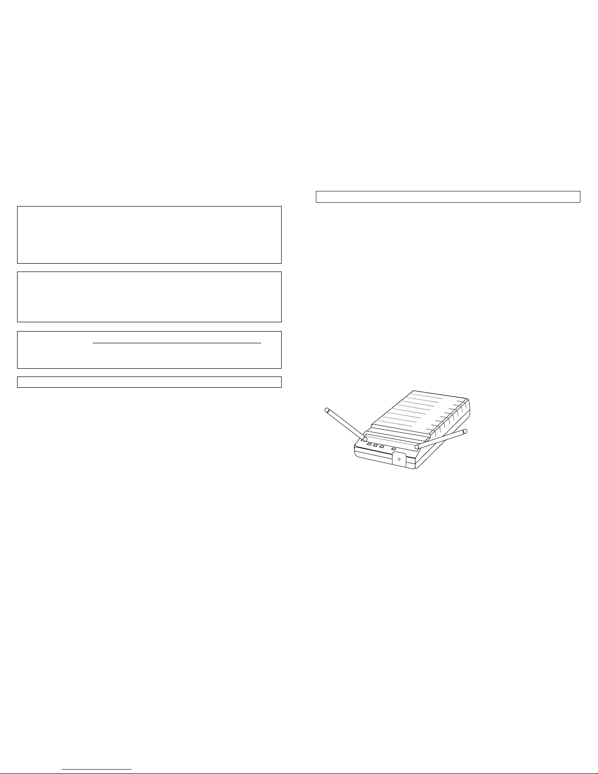
Antennas
The antennas normally should be positioned in the shape of a “V” (45° from vertical) for best
reception (Fig. A).
3
Fig. A
2
Introduction
Thank you for choosing an Audio-Technica professional wireless system. You have joined
thousands of other satisfied customers who have chosen our products because of their quality,
performance and reliability. This wireless microphone system is the successful result of years of
design and manufacturing experience.
This professional wireless system includes a receiver and either a body-pack or a handheld
transmitter on a specific crystal-controlled frequency.
The receiver features true diversity reception. Two antennas feed two completely independent
RF sections on the same frequency; automatic logic circuitry continuously compares and selects
the superior received signal, providing better sound quality and reducing the possibility of interference
and dropouts.
The versatile UniPak™body-pack transmitter has both low- and high-impedance inputs plus a
bias connection, for use with dynamic and electret condenser microphones, as well as Hi-Z
instrument pickups. Both the handheld and UniPak transmitters use internal 9-volt batteries and
have Off/Standby/On switches, battery condition indicators, and battery-save switches.
Please note that in a multi-channel application, there must be a transmitter-receiver combination
on a
separate
frequency for each input desired (only one transmitter for each receiver). Operating
frequency information will be found on page 9.
CAUTION! Electrical shock can result from removal of the receiver cover. Refer servicing to
qualified service personnel. No user-serviceable parts inside. Do not expose to rain or moisture.
The circuits inside the receiver and transmitter have been precisely adjusted for optimum
performance and compliance with federal regulations. Do not attempt to open the receiver
or transmitter. To do so will void the warranty, and may cause improper operation.
Notice to individuals
with implanted cardiac pacemakers or AICD devices:
Please read the cautionary notice on back cover before operating this or any other source
of RF (radio frequency) energy.
This device complies with part 15 of the FCC Rules. Operation is subject to the condition that
this device does not cause harmful interference.
This device complies with INDUSTRY CANADA R.S.S. 210, en conformité avec IC:
RSS-210/ CNR210. Operation is subject to the following conditions: 1) This device may not
cause harmful interference and 2) this device must accept any interference received,
including interference which may cause undesired operation.
Installation and Operation
Move the white arm down until it presses on the battery, then slide the lower body portion back
up until it covers the battery and engages the threads of the upper body. Screw the body back
together; do not overtighten.
Move the power switch on the bottom of transmitter to “On” and make certain the red battery
condition indicator is strongly illuminated.
Return the power switch to the “Off” position.
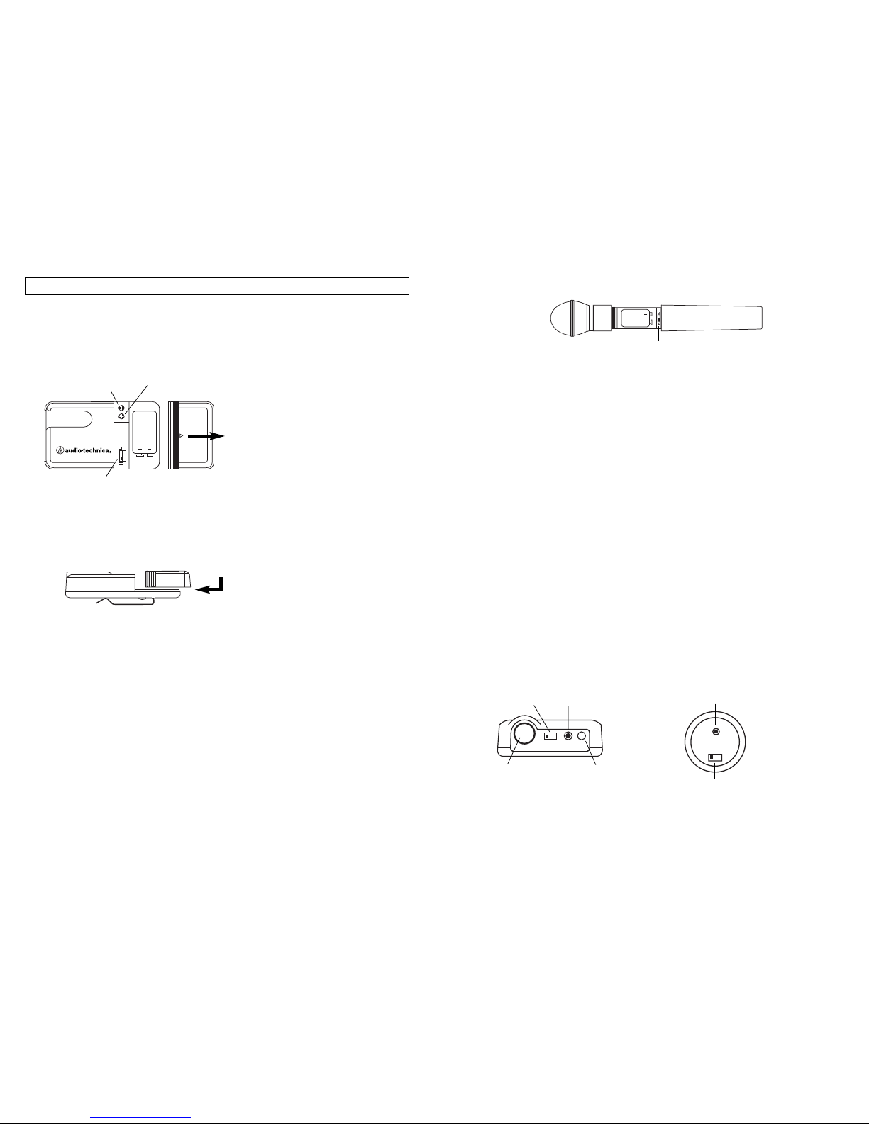
Battery Condition Indicator
The red battery condition indicator (Fig. E/F) should light strongly with a fresh battery. As the
battery weakens, the indicator will grow dimmer. When the indicator becomes very dim or goes
out, there is little life left in the battery. Replace it at once for continued operation of the transmitter.
Battery-Save Switch
All transmitters feature battery-save switches (Fig. B/D). As supplied, the switch is set in the High
position for maximum range. Switching to the Low position increases battery life by reducing
power. (Note: Effective range decreases when the switch is set in the Low position.)
UniPak™Transmitter Input Connection
Connect an audio input device (microphone or guitar cable) to the audio input connector on the
bottom of the transmitter. A number of Audio-Technica professional microphones and cables are
available separately, pre-terminated with a UniPak input connector (see ”Optional System
Accessories“ on page 11).
Transmitting Antenna
The UniPak transmitter includes a permanently-attached flexible antenna. For best results, allow
the antenna to hang freely and full length from the bottom of the transmitter. If the received signal
is marginal, experiment with different transmitter positions on your body or instrument; or try
repositioning the receiver.
Do not attempt to remove, replace or change the length of the
transmitting antenna.
5
Fig. E Fig. F
BATT.
ON OFF
ST.BY
INPUT POWER BATT. ANT
OFF
ONST
Battery Condition
Indicator
Power Switch
On/Standby /Off
Battery Condition
Indicator
Input
Connector
Power Switch
Off/Standby /On
Antenna
Fig. D
Battery Polarity
Diagram
Battery-Save
Switch
Transmitter Setup
Battery Selection
An alkaline 9-volt battery is recommended.
UniPak™Transmitter Battery Installation
Make certain the power switch on the bottom of transmitter is in the “Off” position.
Slide off the battery cover as shown in Figure B.
4
Carefully insert a fresh 9-volt alkaline battery, observing correct polarity as marked inside the
battery compartment. The transmitter housing is designed to prevent incorrect installation of the
battery.
Do not force the battery in.
Replace the battery cover (Fig. C).
Move the power switch to “On” and make certain the red battery condition indicator is strongly
illuminated.
Return the power switch to the “Off” position.
Handheld Transmitter Battery Installation
Make certain the power switch on the bottom of transmitter is in the “Off” position.
While holding the upper part of the transmitter body just below the ball-screen, unscrew the lower
body and slide it downward to expose the battery compartment (Fig. D).
Do not attempt to pull the
lower body farther down, or to gain access to the electronics.
Lift the white “battery keeper” arm until it sticks straight out from the mic body (no higher). Then
carefully insert a fresh 9-volt alkaline battery, observing correct polarity as marked inside the battery
compartment. The transmitter housing is designed to prevent incorrect installation of the battery.
Do not force the battery in.
Fig. B
Fig. C
TRANSMITTER
UniPak™
Battery Polarity
Diagram
Battery-Save Switch
(under screwdriver clip)
Guitar Trimmer
(GT)
Microphone
Trimmer (MT)
 Loading...