

Page 1

Instruction Manual - Installation Edition -
ATUC-IR
Hybrid Infrared Conference System
Gooseneck Microphone with LED Ring
ATUC-M43H/58H/M32L
IR Discussion Unit
ATUC-IRDU
Hybrid Control Unit
ATUC-IRCU
Hybrid Control Unit (Dante-Enabled)
ATUC-IRCUDAN
IR Transmitter Unit
ATUC-IRA
IR Distributor
ATUC-IRD
Charger
ATCS-B60
Page 2

Table of Contents
1. Confirming the Size of the Room Intended for Installation ................................. 2
1.1 Names of IRA Parts ............................................................................................................................. 2
1.2 Image of IRA Installation ..................................................................................................................... 2
2. Confirming the Operating Space ......................................................................... 3
2.1 Relationship Between Ceiling Height and Transmission Area for Ceiling Installation of IRA .............. 3
2.2 Image of Effective Infrared Range of IRA ............................................................................................ 4
2.3 Image of Effective Infrared Range of IRDU ......................................................................................... 4
3. Confirming the Operating Arrangements ............................................................ 5
3.1 Images of Installations in U Shapes and Square Shapes .................................................................... 5
3.2 Images of Installations in School Formats ........................................................................................... 5
3.3 Installation Examples ........................................................................................................................... 6
4. Checking for Interference to Infrared Transmissions ........................................ 14
5. Confirming Wiring and Cable Lengths .............................................................. 15
5.1 When Using IRDs ............................................................................................................................... 15
5.2 Confirming Wiring Plans ..................................................................................................................... 17
5.3 Calculations ........................................................................................................................................ 18
Device Names
The device names are abbreviated in this manual as follows.
· IRCU: “Hybrid Control Unit” ATUC-IRCU
· IRCUDAN: “Hybrid Control Unit (Dante-Enabled)” ATUC-IRCUDAN
· IRDU: “IR Discussion Unit” ATUC-IRDU
· IRA: “IR Transmitter Unit” ATUC-IRA
· IRD: “IR Distributor” ATUC-IRD
· B60: “Charger” ATCS-B60
Symbols
NOTICE
Indicates a risk that may result in malfunction or damage to the device.
Indicates supplementary information as well as tips & advice for operations.
Installation
· After installing an IRA, confirm that it is securely fixed in place.
· Do not install the IRA or the IRDU near anything that generates infrared light, such as direct sunlight, incandescent lights,
halogen lights, inverter-type fluorescent lights, or plasma displays. Noise could be generated regardless of the effective range.
If noise is being generated, you need to install the IRAs and IRDUs in suitable locations.
· Do not place any obstacles around the IRDUs.
· Do not exceed 100 meters for the total length of cable connections.
· When installing multiple IRAs, use the same length for the total length of each of the cables from the IRAs to the IRCU/IRCUDAN.
(We recommend a difference of less than 3 m.)
· Contact our sales representative if you are going to use multiple monitor channels at the same time.
1
Page 3
1. Confirming the Size of the Room Intended for Installation
Checkpoints ① Width, length, ceiling height, existence of windows, etc.
② Does construction of the ceiling allow for installation (ceiling surface,
existence of space above ceiling)
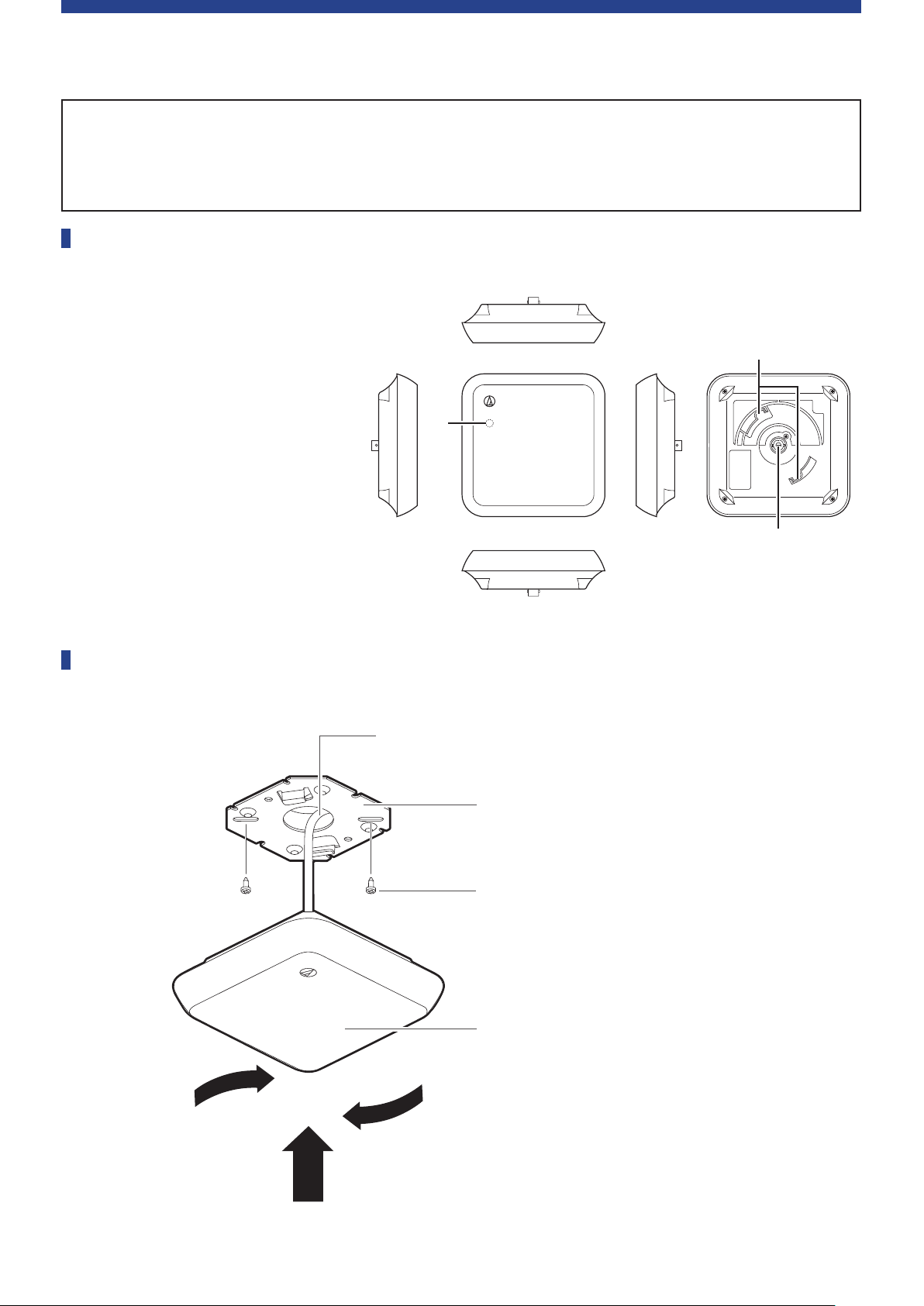
1.1 Names of IRA Parts
① Power LED
Lights when the power to
the IRCU is on, after wiring is
complete.
② Hook for mounting
Use to mount on the mounting
bracket (included accessory).
③ BNC connector
· BNC cables are not included
accessories.
①
②
1.2 Image of IRA Installation
③
BNC cable (from IRCU/IRCUDAN)
Mounting bracket (included accessory)
Screws for mounting bracket (included accessory)
② Rotate
IRA
① Insert
2
Page 4
2. Confirming the Operating Space
Checkpoints ① Coverage area, number of units, and distance between units when
mounting IRA on a ceiling
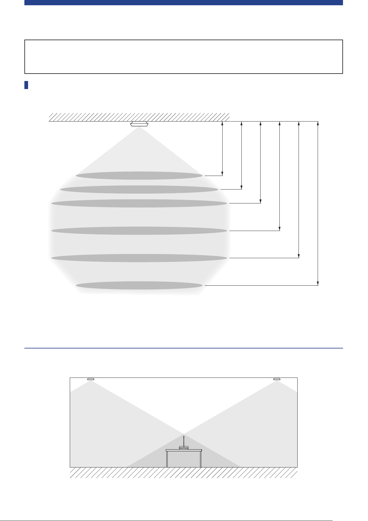
2.1 Relationship Between Ceiling Height and Transmission Area for Ceiling Installation of IRA
2. 4 m
2. 7 m
3 m
Approximately φ 5 m*
Approximately φ 6 m*
Approximately φ 7 m*
Approximately φ 7 m*
Approximately φ 7 m*
Approximately φ 5 m*
* Transmission Area
4 m
5 m
6 m
Elevation Diagram
3
Page 5
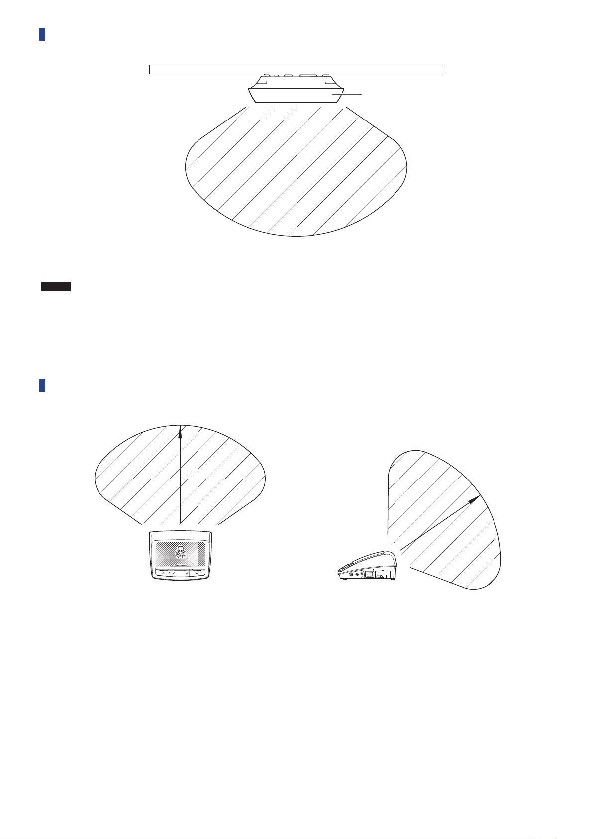
2.2 Image of Effective Infrared Range of IRA
IRA
NOTICE
· Infrared transmissions cannot reach the IRA if they are hidden or blocked by users.
· Install multiple IRAs so they can be seen from the IRDUs
· Do not cover the infrared transmitter with your hand or anything else.
2.3 Image of Effective Infrared Range of IRDU
PUSH
4
Page 6
3. Confirming the Operating Arrangements
Checkpoints ① Confirm operating format: U shape, square shape, school format, etc.
② Distance between and orientation of IRDUs and IRAs
· Be sure to install an IRA in front of the IRDUs so the IRDUs can transmit.
· For specific installation positions, contact our sales representative.
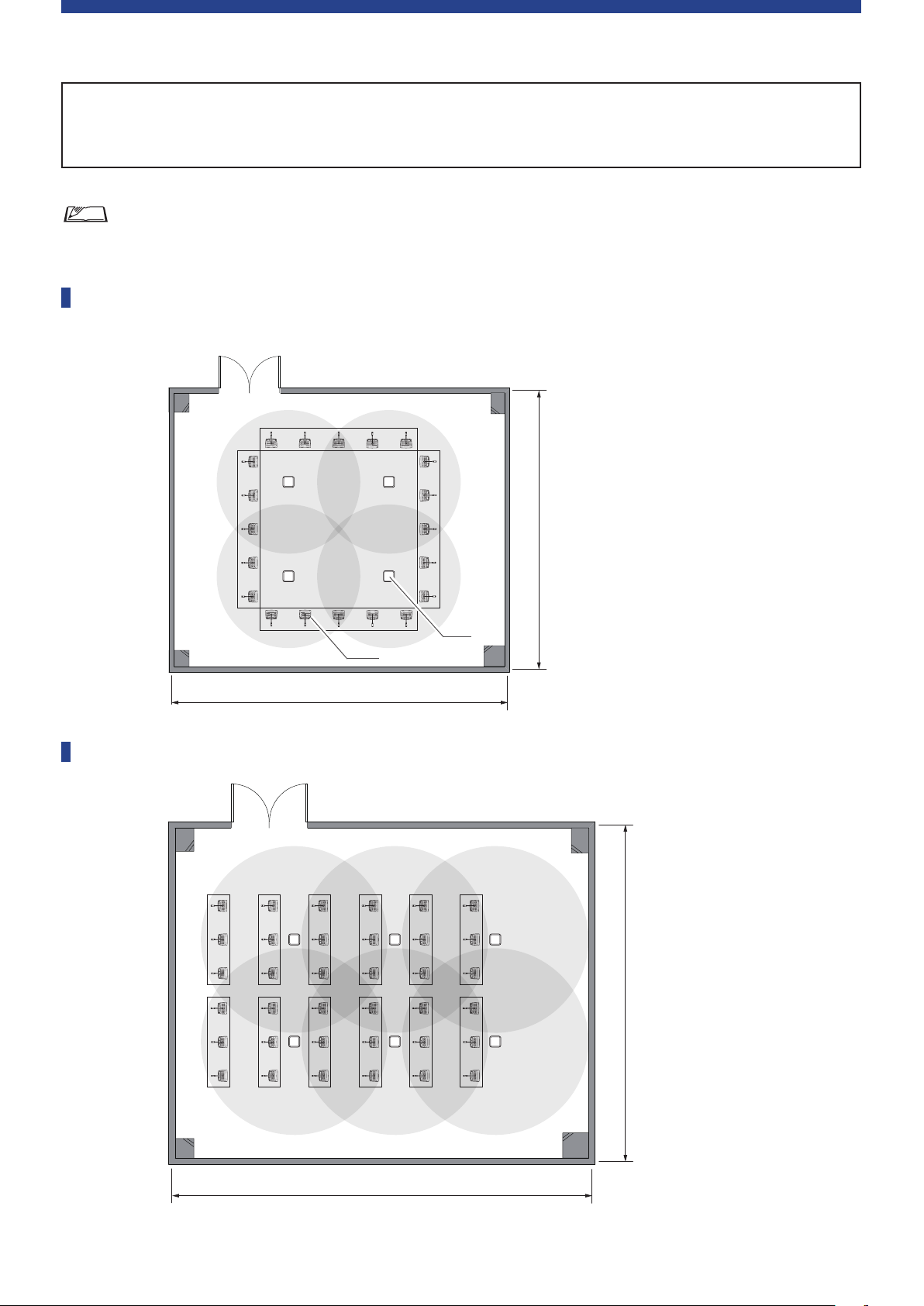
3.1 Images of Installations in U Shapes and Square Shapes
· The following diagram shows a square shape.
10 m
IRA
IRDU
12 m
3.2 Images of Installations in School Formats
15 m
12 m
5
Page 7
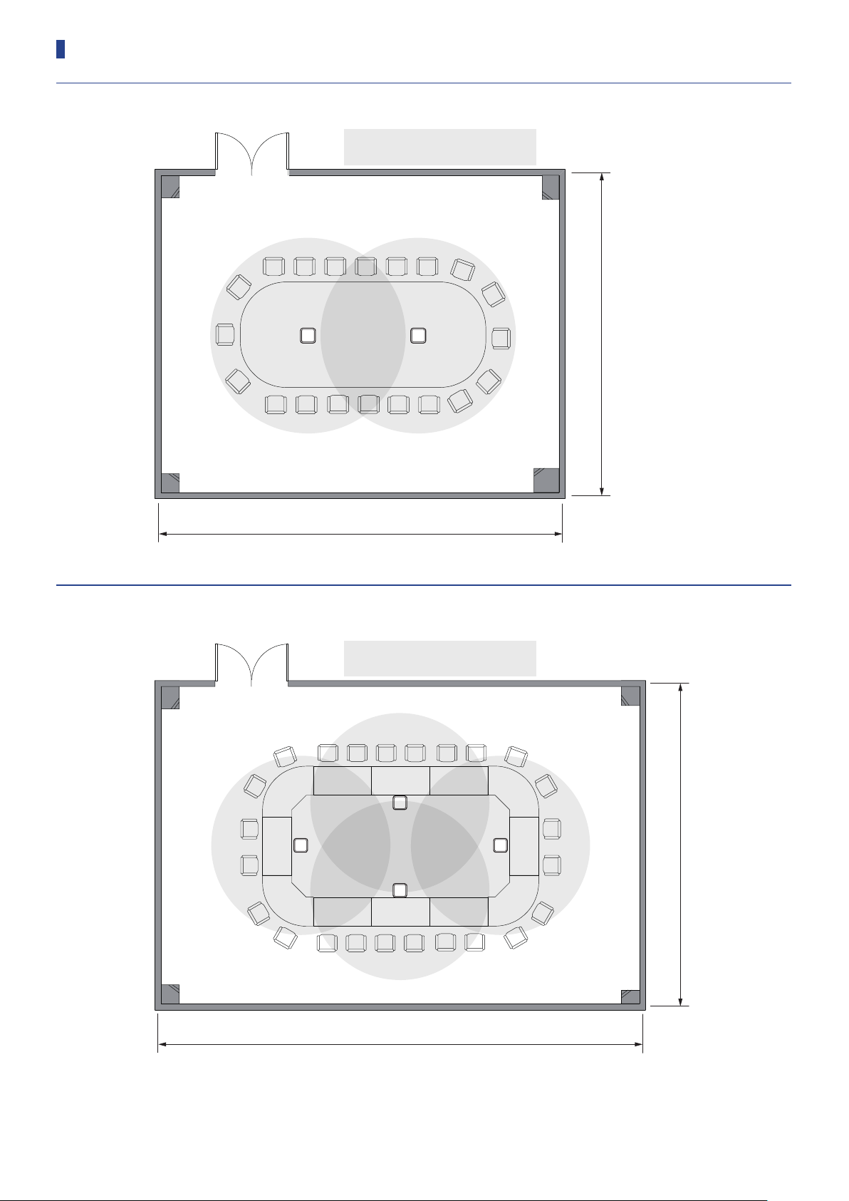
3.3 Installation Examples
Round table [W: 10 m, D: 8 m, H: 2.4 m], transmission area: approximately φ5 m
Ceiling height: 2.4 m
8 m
10 m
Square shape (small) [W: 12 m, D: 8 m, H: 2.4 m], transmission area: approximately φ5 m
Ceiling height: 2.4 m
8 m
12 m
6
Page 8

Square shape (large) [W: 15 m, D: 12 m, H: 2.7 m], transmission area: approximately φ6 m
Ceiling height: 2.7 m
12 m
15 m
U shape + back area seats [W: 15 m, D: 12 m, H: 2.4 m],
transmission area: approximately φ5 m
Ceiling height: 2.4 m
12 m
15 m
7
Page 9

Long U shape desks [W: 18 m, D: 12 m, H: 2.7 m], transmission area: approximately φ6 m
Ceiling height: 2.7 m
12 m
18 m
Long U shape + desks on both sides [W: 18 m, D: 12 m, H: 2.4 m],
transmission area: approximately φ5 m
Ceiling height: 2.4 m
12 m
18 m
8
Page 10

V shape [W: 15 m, D: 12 m, H: 2.7 m], transmission area: approximately φ6 m
Ceiling height: 2.7 m
12 m
15 m
School format (horizontal) [W: 18 m, D: 12 m, H: 2.7 m],
transmission area: approximately φ6 m
Ceiling height: 2.7 m
12 m
18 m
9
Page 11

School format (vertical) [W: 8 m, D: 12 m, H: 2.4 m],
transmission area: approximately φ5 m
Ceiling height: 2.4 m
12 m
8 m
10
Page 12

School format (vertical) [W: 13 m, D: 20 m, H: 2.7 m],
transmission area: approximately φ6 m
Ceiling height: 2.7 m
20 m
13 m
11
Page 13

School format (vertical)
[W: 17 m, D: 16 (26) m, H: 2.7 (5) m], transmission area: approximately φ6 m
17 m
26 m
16 m
Ceiling height (minimum): 2.7 m
(maximum): 5 m
2.7 m
5 m
12
Page 14

School format (maximum 16 units) [W: 20 m, D: 20 m, H: 2.7 m],
transmission area: approximately φ6 m
Ceiling height: 2.7 m
20 m
20 m
13
Page 15

4. Checking for Interference to Infrared Transmissions
Checkpoints ① Interference from sunlight, lighting (incandescent lights, downlights,
halogen, etc.), plasma displays, and the position to install the IRAs
About Installation
· The effective range of the infrared transmissions varies depending on the color and material used for ceilings,
walls, and other things.
· Noise could be generated regardless of the effective range.
If this happens, you need to install the IRAs and IRDUs in suitable
locations.
· Do not place any obstacles around the IRDUs.
· Block sunlight with curtains or blinds so it does not shine directly on the
equipment.
· If you install IRAs on the ceiling, install them so they are at least 2 meters
away from windows and walls. (Refer to diagram on right.)
If you want to install them within 2 meters, contact our sales representative.
· Install IRAs at least 50 cm away from fluorescent lights.
·
Implement the following measures in cases where there is a risk of static interference from audio equipment or TVs.
- The high-frequency currents that flow through power lines and load lines generate magnetic fields that may
affect nearby audio signal lines.
Measure A: Separate wires to the IRAs and wires to audio and TV antenna equipment (microphone cords,
etc.) by at least 1 meter from lighting control wires (load lines and power lines). (Refer to
diagram below.)
Measure B: Use separate conduits for the lighting control wires and audio equipment wires. (Refer to
diagram below.)
Measure C: Be sure to use D-type (type 3) ground connections for IRCU/IRCUDAN, lighting controls, and
audio controls.
- Implement sufficient precautions because simultaneous interpretation systems and medical equipment may be
affected by nearby lighting controls or lighting fixtures that are being controlled.
2 m
Window or
wall
Power lines and load lines (in conduits)
Separate by at least 1 m
Audio equipment wiring and wiring to IRAs (in conduits)
· If you install IRAs or IRDUs near the following sources that produce infrared light, they may cause the generation
of noise or malfunctions in the system.
- Lighting equipment
- Projectors (LCD, DLP, etc.), OHP, incandescent
light bulbs, etc.
- Mercury vapor lights, halogen lights, and invertertype fluorescent lights
- Plasma displays
- Lighting controls
- Infrared equipment, such as remote controls,
infrared microphones, and infrared LAN
- Digital equipment and wiring, such as digital
power amplifiers (speaker wires from digital power
amplifiers, etc.)
- Wi-Fi routers
Lighting control
equipment
Separate by at least 5 m
Audio
equipment
IRCU/
IRCUDAN
14
Page 16

5. Confirming Wiring and Cable Lengths
Checkpoints ① Do not exceed 100 meters for the total length of cable connections.
When installing multiple IRAs, use the same total cable lengths from the IRAs to the IRCU/
IRCUDAN. (We recommend a difference of less than 3 m.)
5.1 When Using IRDs
Names of IRD parts
②
①
① BNC connectors
· BNC cables are not included accessories.
② Mounting holes
Holes to mount IRD
Wiring for IRAs and IRCU/IRCUDAN
You can install up to four IRAs from each TX/RX terminal on the IRCU/IRCUDAN. A maximum of 16
IRAs can be installed by using IRDs.
IRA
Maximum of four units for each TX/RX terminal
1 2
3 4
IRD
IRD
15
IRCU/IRCUDAN
Page 17

Length of wiring cables
If the phase of the input signals to each IRA is not the same phase, the reception levels may drop. To
synchronize the phases of the signals, use the same total cable lengths from the IRAs to the IRCU/
IRCUDAN.
IRA
L3 L3
L2
L1
· Length of cables from IRA to IRCU/IRCUDAN: L1 = L2 + N1 = L3 + M1 + N1
· Keep the differences in the L1, L2 + N1, and L3 + M1 + N1 cables to within ±3 m.
L2
L3 L3
IRD
M1M1
IRD
N1N1
IRCU/IRCUDAN
16
Page 18

5.2 Confirming Wiring Plans
The wiring between the IRAs and the IRCU/IRCUDAN must meet the following two criteria.
①
Maximum allowable loss in wiring circuit (total loss of cables and distributors): 15 dB or less
② Maximum allowable drop in DC voltage: 3 V or less
Use the above values to do the wiring.
Values needed to calculate losses
① IRD loss: 4 dB
② Attenuation per 100 m of coaxial cable
3C-2V 4.2 dB RG-59U 3.0 dB
5C-2V 2.7 dB RG-6U 2.3 dB
7C-2V 2.2 dB RG-11U 1.3 dB
Values needed to calculate drop in voltage
① Operating current for each IRA: 0.09 A
② Resistance of IRD: 0.5 Ω
③ Loop resistance per 100 m of coaxial cable (at 20°C)
3C-2V 9.14 Ω RG-59U 4.5 Ω
5C-2V 3.59 Ω RG-6U 3.0 Ω
7C-2V 2.07 Ω RG-11U 1.3 Ω
· The attenuation and loop resistance values for coaxial cable are reference values. Check the
values of the cables you are using for your actual installation.
17
Page 19

5.3 Calculations
Calculating losses in wiring circuits
Conditions: Total attenuation ≦ 15 dB
Attenuation of cable = (length/100) × attenuation per 100 m
Total attenuation = Attenuation of coaxial cable 1 + attenuation of coaxial cable 2 + attenuation of
coaxial cable 3 + attenuation of IRD1 + attenuation of IRD2)
IRCU/IRCUDAN
IRD1 IRD2
Coaxial cable 1
Attenuation of coaxial
cable 1
Conditions: Total voltage drop ≦ 3 V
Voltage drop of cable = (length/100) × loop resistance per 100 m of cable × current
Current flowing in cable = Number of IRAs connected to one TX/RX terminal × 0.09 A
Total voltage drop = Voltage drop 1 + voltage drop 2 + voltage drop 3
IRCU/IRCUDAN
Coaxial cable 2 Coaxial cable 3
Attenuation of coaxial
cable 2
Attenuation of coaxial
cable 3
IRA
IRD1 IRD2
Coaxial cable 1
Current 1
Voltage drop 1 Voltage drop 2 Voltage drop 3
Coaxial cable 2
Current 2 Current 3
Coaxial cable 3
IRA
18
Page 20

Example 1: When 4 IRAs are installed
i
n
n
d
o
C
1) Calculating maximum allowable loss of cables
s
o
i
t
A
s
:
s
u
m
u
s
e
d
.
h
e
i
n
g
d
t
i
IRCU/IRCUDAN
s
t
a
n
c
e
R
/
U
I
I
C
m
r
o
f
V
2
c
a
o
R
D
U
C
A
50 m
N
R
I
o
A
t
s
i
s
5
W
.
h
m
0
IRA
-
C
e
5
n
i
a
x
c
l
a
b
l
e
i
s
Attenuation from IRCU/IRCUDAN to IRAs
= 2.7 dB × (50 m/100 m) = 1.35 dB
Result is less than maximum allowable loss (15 dB).
2) Calculating maximum allowable voltage drop of cables
Voltage drop from IRCU/IRCUDAN to IRAs
= 3.59 Ω × (50 m/100 m) × 0.09 A
= 0.16 V
Result is less than maximum allowable drop in voltage (3 V).
Use cable lengths that stay within the maximum allowable losses and maximum allowable voltage
drops.
19
Page 21

Example 2: When 16 IRAs are installed
i
n
n
d
o
C
s
o
i
t
A
s
:
s
u
m
R
I
2
D
h
e
i
n
g
d
t
i
i
s
0
1
s
a
t
n
c
e
a
h
,
m
e
n
d
d
t
R
I
C
m
r
o
f
i
s
a
t
n
c
e
f
h
e
d
t
i
R
D
/
U
U
I
C
A
t
R
I
2
D
m
r
o
N
o
R
I
o
D
t
R
I
i
A
s
0
1
1
W
.
h
m
0
2
e
,
m
i
s
s
a
t
n
c
e
V
2
c
a
o
-
C
5
n
R
I
1
D
m
r
o
f
i
a
x
c
l
a
b
l
e
i
s
u
s
e
d
.
o
t
IRCU/
IRCUDAN
IRD2
IRD1
10 m 10 m 20 m
IRA
1) Calculating maximum allowable loss
① Attenuation from IRCU/IRCUDAN to IRD1 = 2.7 dB × (10 m/100 m) = 0.27 dB
② Attenuation from IRD1 and 2 = 2.7 dB × (10 m/100 m) = 0.27 dB
③ Attenuation from IRD2 to IRA = 2.7 dB × (20 m/100 m) = 0.54 dB
④ Loss from IRD1 and 2 = 4 dB + 4 dB = 8 dB
The total attenuation from the cables and loss from the IRDs is 9.08 dB (0.27 dB + 0.27 dB + 0.54 dB +
8 dB), which is less than the maximum allowable loss (15 dB).
2) Calculating maximum allowable drop in voltage
① Voltage drop from IRCU/IRCUDAN to IRD1
= 3.59 Ω × (10 m/100 m) × 0.09 A × 4 = 0.129 V
② Voltage drop of IRD1 = 0.5 Ω × 0.09 A × 4 = 0.18 V
③ Voltage drop between IRD1 and 2 = 3.59 Ω × (10 m/100 m) × 0.09 A × 2 = 0.064 V
④ Voltage drop of IRD2 = 0.5 Ω × 0.18 A = 0.09 V
⑤ Voltage drop between IRD2 and IRA = 3.59 Ω × (20 m/100 m) × 0.09 A = 0.064 V
The total voltage drop is 0.527 V (0.129 V + 0.18 V + 0.064 V + 0.09 V + 0.064 V), which is less than the
maximum allowable voltage drop (3 V).
20
Page 22

Audio-Technica Corporation
2-46-1 Nishi-naruse, Machida, Tokyo 194-8666, Japan
www.audio-technica.com
©2018 Audio-Technica Corporation
Global Support Contact: www.at-globalsupport.com
ver.1 2018.09.01142900220-02-01
 Loading...