

Page 1
Instruction manual
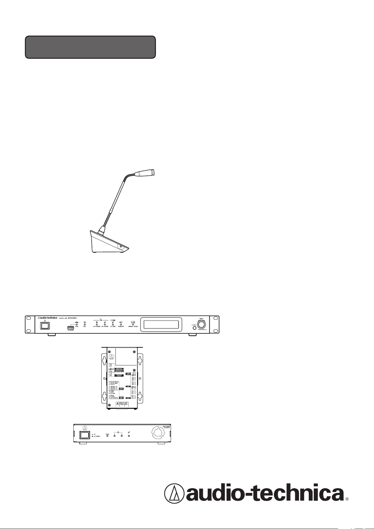
Digital Conference System
ATUC-50
Gooseneck Microphone with LED Ring
ATUC-M43H/58H
Discussion Unit
ATUC-50DU
Interpretation Unit
ATUC-50INT
Control Unit
ATUC-50CU
Integration Unit
ATUC-50IU
Link Extender
ATLK-EXT165
Page 2

Table of Contents
Introduction .......................................... 4
About this manual .................................................. 4
About the information in this manual ..................................... 4
About registered trademarks and copyrights .......................... 4
Included accessories for the ATUC‑50CU .............. 4
Included accessories for the ATUC‑50IU ............... 4
Included accessories for the ATLK‑EXT165 ...........4
System placement ..................................................5
Installing the CU(s) in a rack ................................................... 5
Unbalanced connection ............................................................ 5
AC power cord connection ....................................................... 5
When cleaning the units ........................................................... 5
ATUC-50 System ..................................... 6
Features ..................................................................6
Features of ATUC-50 system ................................................... 6
About Audio-Technica LINK ................................................... 6
Features of ATUC-50CU .......................................................... 6
Features of ATUC-50DU/INT ................................................ 6
Features of ATUC-50IU ........................................................... 6
Features of ATLK-EXT165 ....................................................... 7
Features of ATUC-M43H/58H ................................................ 7
Optional products (sold separately by Audio Technica) ........ 7
Connection example of digital conference
system ATUC‑50 ......................................................8
Part Names and Functions ..................... 9
ATUC‑50CU .............................................................. 9
Front panel ................................................................................ 9
Rear panel ................................................................................ 11
ATUC‑50DU ........................................................... 12
ATUC‑50INT ........................................................... 13
Common to ATUC‑50DU/INT ................................ 14
ATUC‑M ................................................................. 14
ATUC‑50IU ............................................................. 15
ATLK‑EXT165 .........................................................21
Changing settings from ATUC‑50CU ...................22
Entering letters ....................................................23
Overview of the Interpretation Unit
(ATUC‑50INT) ........................................................24
System Connections and
Configuration ...................................... 26
Connecting devices .............................................. 26
Connecting the DUs/INTs to the CU .............................. 26
1
Connecting the DUs/INTs together ................................ 27
2
Connecting the microphone ATUC-M to
3
the DU/INT ...................................................................... 30
Connecting an amplifier ................................................... 30
4
Turning on the CU and testing DU operations ............... 30
5
Connecting to a network .................................................. 31
6
Connecting a computer or mobile device to a network .. 31
7
Preparing to use Web Remote .............................33
What is Web Remote? ............................................................. 33
Setting up “Locate” ................................................................. 33
Configuring and Operating
Conferences Using the Web Remote
Control Function .................................. 34
About Web Remote ..............................................34
Overall structure of Web Remote .......................................... 34
Starting up Web Remote and preparing
for operations .......................................................35
Starting up and logging in to Web Remote ............................ 35
About Web Remote Home screen .......................................... 35
Configuring detailed system settings
([Settings & Maintenance]) .................................. 36
How to operate the [Settings & Maintenance] menu ........... 36
Menu item ① ([System Settings]) ........................................ 37
Menu item ② ([Install Settings]) .......................................... 42
Accessing your presets ([Presets]) ........................................ 54
Log management ([Logging]) ............................................... 54
Displaying the system information ([System Info]) ............. 54
Preparing for conferences
([Setup Conference]) ............................................55
Recalling the preset ([Recall Preset]) ............................. 55
1
Changing the conference settings
2
([Conference Settings]) ................................................... 55
Adjusting the DU/IU settings
3
([DU/IU Settings], [DU/IU Detail Settings]) ............... 56
Operating and controlling conferences
([Start Conference]) .............................................57
Operating conferences ([Conference Manager]) ............ 57
1
Configuring the advanced audio-related settings and
2
performing audio operations ([Audio Control]) ............ 58
Configuring conference settings
3
([Conference Settings]) ................................................... 58
2
Page 3

Information.......................................... 59
Troubleshooting ...................................................59
ATUC-50CU ........................................................................... 59
ATUC-50DU/INT ..................................................................60
Web Remote ............................................................................ 61
ATUC-50IU ............................................................................61
ATLK-EXT165 ........................................................................ 61
Error messages .....................................................62
Specifications ...................................... 66
ATUC‑50CU specifications .................................... 66
General specifications ............................................................ 66
Input/output specifications ................................................... 67
ATUC‑50DU/INT specifications ............................ 68
General specifications ............................................................ 68
Input/output specifications ................................................... 69
ATUC‑50IU specifications ..................................... 70
General specifications ............................................................ 70
ATLK‑EXT165 specifications ................................. 72
General specifications ............................................................ 72
ATUC‑M specifications ......................................... 73
3
Page 4

Introduction
About this manual
About the information in this manual
The images and screenshots shown in this manual may differ from
the actual product.
Device names
The device names are abbreviated as follows.
• CU: “Control Unit” ATUC-50CU
• DU: “Discussion Unit” ATUC-50DU
• INT: “Interpretation Unit” ATUC-50INT
• ATUC-M: “Gooseneck Microphone with LED Ring”
ATUC-M43H/ATUC-M58H
• IU: “Integration Unit” ATUC-50IU
• EXT: “Link Extender” ATLK-EXT165
Symbols
➤
NOTICE
[ ]
Indicates the page(s) where you can find more detailed
or related information.
Indicates a risk that may result in malfunction or damage
to the device.
Indicates supplementary information as well as tips &
advice for operations.
Indicates menu items on the Web Remote screen.
Included accessories for the
ATUC-50CU
The following accessories and documentation are provided.
• AC power cord
• Euroblock connector (9 pieces)
• Quick Setup Guide—English version
• Quick Setup Guide—Multi-language version
Included accessories for the
ATUC-50IU
The following accessories and documentation are provided.
• Euroblock connector (13 pieces (Green x 3, Black x 10))
• Quick Start Guide—Multi-language version
Included accessories for the
ATLK-EXT165
Operations on mobile devices
Operations in this manual assume that you are using a computer as a
control device. Alternatively you can use a mobile device such as a
tablet. Instead of clicking or double-clicking, operate the application
by tapping.
About registered trademarks and
copyrights
• Apple, the Apple logo, iPad and Mac OS are trademarks of Apple
Inc., registered in the U.S. and other countries. App Store is a
service mark of Apple Inc.
• Google Play and the Google Play logo are registered trademarks
or trademarks of Google Inc.
• Other product names, service names, logos and/or company
names used in this manual are trademarked and copyrighted
properties of their respective owners and/or licensors.
In this manual, the TM and
mark may not be specified.
®
The following accessories and documentation are provided.
• Euroblock connector
• Power cable
• Table mount kit (Table mount x 2, Screw x 4)
• Quick Start Guide—Multi-language version
4
Page 5

System placement
Installing the CU(s) in a rack
Rack requirements for the CU
• EIA standard compatible 19-inch rack
• 1U-size rack mounting
• Rack equipped with safety guardrails to support the CU and a
board on which the CU is to be placed
When installing the CU(s) in a rack, keep the temperature within
the rack below 45°C (113°F). High temperature may damage the
internal components, causing a malfunction.
Leave a space of 10cm or more on each side (top, right and left,
rear) between the CU and other devices or the rack.
Rack mounting angles are fixed to the CU using the following
screws. When using screws other than those listed here, check the
specifications.
• S TIGHT tapping screws with nominal diameter 4×6mm*
* Substitutable for M4×6mm machine screws
Unbalanced connection
Since induction noises tend to occur due to difference in electric
potential of chassis:
• Keep the chassis between each device at the same electric
potential.
• Use the same power system.
• Connect to the GND (ground) terminal or chassis ground of each
device.
AC power cord connection
Be sure to connect the AC power cord into a properly grounded wall
outlet. Improper grounding can cause electrical shock.
When cleaning the units
Do not use any solvents or chemicals such as benzine, thinner,
alcohol or electrical contact cleaner and protector. Doing so may
cause deformation, damage and malfunction of the units.
5
Page 6

ATUC-50 System
Features
Features of ATUC‑50 system
• Audio processing by the feedback processor and the like enables
clear-sounding conversations
• Up to 6 interpretation units (ATUC-50INT) can be connected.
• The maximum number of discussion unit (ATUC-50DU),
integration unit (ATUC-50IU), and interpretation unit (ATUC50INT) connections is 300 (with 3 CU Links)
• Either daisy-chain or ring connection can be made with Cat5e or
higher cables (shielded cables with conductor size of 24AWG or
higher in diameter are recommended).
• 3 selectable conference modes: Free Talk Mode, Request Talk
Mode, and Full Remote Mode
• 2-language interpretation, 3-language interpretation, and
3-language relay interpretation are supported (ATUC-50INT)
• The recording function enables you to record audio onto a USB
device (mass storage device)
• Controllable using Web Remote and an external control device
• Design with future expansion considered
About Audio‑Technica LINK
The system adopts the unique format Audio-Technica LINK for
power supply and signal transmission between the control unit(s)
(ATUC-50CU), discussion unit(s) (ATUC-50DU), etc.
Audio-Technica LINK is compatible with the Ethernet standards
and allows a simple construction for universal Cat5e or higher cable
connections. (A shielded cable with conductor size of 24AWG or
higher in diameter is recommended.) Transmission of high-speed
signals with low-latency allows stable control and uncompressed
audio signal transmission.
Features of ATUC‑50CU
• Power supply and control is possible for a maximum of 100
discussion units (ATUC-50DU) (depending on the cable lengths
ATLK-EXT165 may be required)
• Up to 300 conference microphones (ATUC-50DU + ATUC-M)
can be connected by cascade-connection
• 4 configurable balanced matrix output plus 1 unbalanced output
that outputs the same audio as Output 1
• 2 Mic/Line inputs, 2 monaural AUX inputs, and 2 return inputs
• 2 return channels are available for both bilingual simultaneous
interpretation and the language of the floor holder
• Conference mode: Free Talk, Request Talk, and Full Remote
• Priority mode: First-press priority and later-press (FIFO, LIFO)
priority
• Talk mode: Manual mode, Voice activation mode
• Web Remote enables you to easily change settings and control
attendees' right to talk during conference
• Up to 4 channels (WAV: up to 4 channels, MP3: up to 2 channels)
can be recorded on a USB device (mass storage device)
• Audio processing by the feedback suppressor and the like enables
the control unit to deliver high-quality sound
• Design with future expansion and renewal considered
Features of ATUC‑50DU/INT
• An LED ring enables power supply via 3-pin balanced connector
while offering both high sound quality and user flexibility
• ATUC-M and standard 3-pin microphone can be connected
• A microphone amplifier with discrete transistors reduces noise;
moreover individual gain is adjustable
• A high-quality and high-resolution speaker
• Designed for the high sound qualities of 24 bit/48 kHz
• Multiple independent indicators (ATUC-M ring LED,
multicolored LEDs both on the rear side and on the
button)
• High-visibility indicators associated with the headphone volume
adjustment buttons and monitor channel selection buttons
• Optional removable bottom weight for improved stability
• 2 RJ-45 terminals for connecting discussion units (ATUC-50DU);
1 expansion RJ-11 terminal for future expansions
• 1 headphone output jack with a monitoring channel switch
function
(talk)
Features of ATUC‑50IU
• Discussion units that can be embedded in the ATUC-50 system
• Configure the system simply by connecting the microphones,
speakers, headphones, etc.
• GPIO control terminal built in for monitoring conditions and
controlling external devices
• Equipped with 2 RJ-45 terminals for connecting discussion units
(ATUC-50DU), etc.
• Designed for the high sound qualities of 24 bit/48 kHz
• Integration unit (ATUC-50IU) can be set from the web remote for
the chairperson/delegate names
• Conference Mode and volume can be set for each integration unit
(ATUC-50IU)
6
Page 7

Features of ATLK‑EXT165
• Connects to any Audio Technica device, such as a control unit
(ATUC-50CU), or discussion unit (ATUC-50DU), and is
equipped with two RJ-45 terminals that can expand the discussion
system
• Remote mode that automatically starts from the control unit
(ATUC-50CU)
• Has a standalone mode that can be started by operating the front
panel
• Equipped with GPO terminal that notifies external devices when
an overcurrent (2.6 A) is detected in the power supplied from
RJ-45 terminals
Features of ATUC‑M43H/58H
• Equipped with an LED ring that enables power supply via 3-pin
balanced connector while offering both high sound quality and
user flexibility
• Adopted mechanics between the microphone connector and the
discussion unit (ATUC-50DU) reduce vibration
• Adopted a double layer pop filter (windscreen inside the
microphone)
• Improves RF measures against external radio waves
• 2 types of microphones (430mm and 580mm length)
Optional products (sold separately by
Audio Technica)
Model
number
ATUC-DUWT DISCUSSION UNIT
AT8643 RACK MOUNT KIT Use this when rack mounting
Name Use
Use this to improve the
WEIGHT PLATE
reliability of installation for
the discussion unit (ATUC50DU).
half-rack sized products, such
as link extenders (ATLKEXT165).
7
Page 8
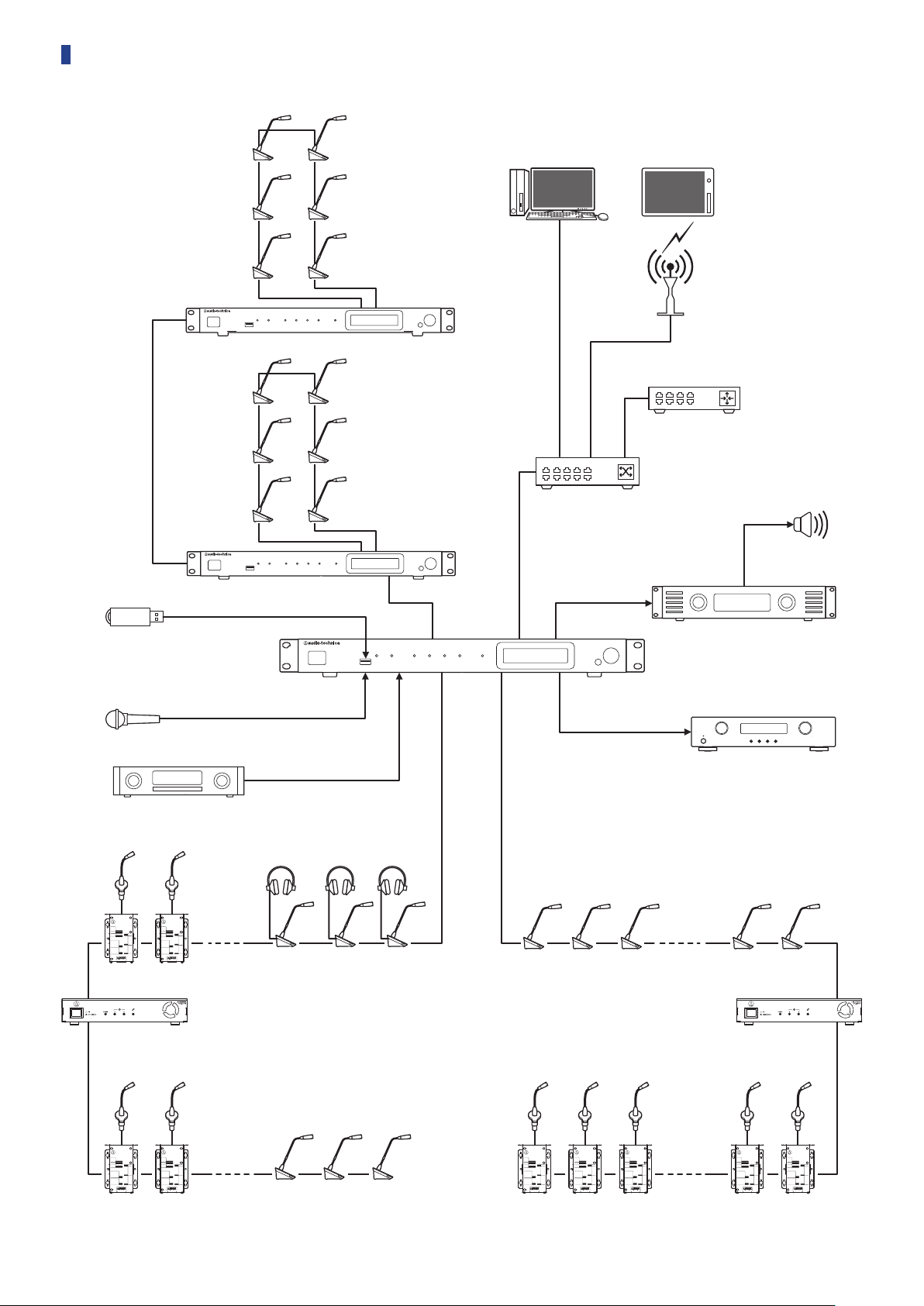
Connection example of digital conference system ATUC-50
CU (extension)
CU (extension)
Windows/Mac
Web Remote
Control
Switching hub
Tablet
Web Remote
Control
AP
Router
Speaker
USB device (mass storage
device) to be used for
recording/SFX
CU (primary)
Microphone
CD player
IU
(Maximum 50 units)* (Maximum 50 units)*
EXT EXT
INT
DU
Amplifier
Recorder
IU
DU
IU
* The number of connectable units differs depending on the system configuration that you are using. For more details, refer to page 28.
8
Page 9

Part Names and Functions
① ② ③ ④ ⑤ ⑥ ⑦ ⑧ ⑩ ⑪ ⑫⑨
ATUC-50CU
Front panel
Power switch
①
Turns the power of the CU on and off.
USB terminal
②
The following operations can be performed by connecting a USB
device (mass storage device) such as a USB flash drive or USB
hard drive.
• Recording sound (
• Playing buzzer and chime (
• Importing/exporting preset data (
• Upgrading the firmware (
NOTICE
③
NOTICE
④
• Supports FAT16 and FAT32 file systems
• Maximum storage capacity: 2TB
• Maximum file size: 2GB
• Does not support USB hubs.
• Do not use extension cables.
• Do not attempt to use USB devices (mass storage
devices) that have been cracked, deformed or repaired
using adhesive tape or the like.
• Do not save or create any files or folders unnecessary for
this system on the USB device (mass storage device);
doing so may affect system operations.
• The CU is not compatible with USB devices (mass
storage device) with special functions such as a security
function.
USB access indicator
Indicates the connection status of the USB device (mass storage
device).
• In an access state: lit green
• Do not remove the USB device (mass storage device)
while the indicator is lit green; doing so may destroy
data.
REC (recording) indicator
Indicates the recording status.
• In a recording state: lit green
• In a recording-pause state: blinks green
• While not recording: remains off
page 58)
➤
page 58)
➤
page 39)
➤
page 54)
➤
NOTICE
⑤
⑥
⑦
⑧
⑨
⑩
⑪
• If you remove the USB device (mass storage device)
while in a recording state or recording-pause state, the
recorded file may not be written correctly. Do not
remove the USB device (mass storage device) during
recording.
DU POWER (DU power supply) indicator
• In a normal state: lit green
• In an abnormal state (such as when a voltage drop occurs in the
48V output system): blinks green
• In a DU/INT disconnected state: remains off
DU CHAIN indicator
• In a normal state: lit green
• In an abnormal state (such as when failing in communication
with a DU): blinks green
• In a DU/INT disconnected state: remains off
CU LINK indicator
• In a CU Link state: lit green
• In an abnormal state (such as when failing in communication
with a CU): blinks green
• In a CU Link cut-off state: remains off
Remote (remote control) indicator
• In a communication state: lit green
• In an abnormal state (such as when failing in external
transmission retry): blinks green
• In a non-communication state: remains off
SIGNAL/PEAK indicator
Indicates the audio signal level as follows:
– 60dBFS or higher: lit green
– 20dBFS or higher: lit amber
– 2dBFS or higher: lit red
Adjust the audio signal level such that the indicator will not light
page 58).
red (
➤
CU display
BACK button
Returns to the previous or upper screen/item.
Press and hold this button to return to the HOME screen from
any screen.
9
Page 10
Jog dial/ENTER button
1 2 3 4
-50 -40 -30 -20 -12 -6 0 6 12
-50 -40 -30 -20 -12 -6 0 6 12
⑫
Rotate the jog dial to select the desired item and then press the
ENTER button to confirm.
Rotating the jog dial also adjusts the setting values.
• Locking the operation buttons (Key Lock function)
Press the BACK button and ENTER button simultaneously for
over 2 seconds to activate the Key lock function, and thus lock
all front panel operations except for the Power switch.
• Unlocking the operation buttons
When the operation buttons are locked, press the BACK
button and ENTER button simultaneously for over 2 seconds
to unlock the operation buttons.
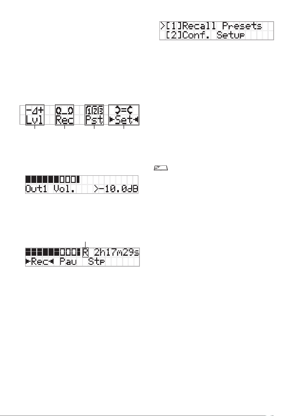
CU display and jog dial operations:
HOME screen
The item with ▶◀ is the currently selected item.
By rotating the jog dial, move ▶◀ to select the operation you
want to perform and then press the ENTER button.
Master level adjustment (Lvl)
1
Master level
Peak (dBu)
Conference preparation (Pst)
3
Recall Presets
• [1]
you want to recall and then press the ENTER button to
confirm.
Conf. Setup
• [2]
Rotate the jog dial to move “>” to the item you want to change
or check and then press the ENTER button to confirm.
Pst Menu Items:
Settings can also be configured via Web Remote. The item
names in parentheses () are used for Web Remote.
Recall Presets
[1]
Conf. Setup
[2]
01 Conference Mode
02 NOM
03 Auto Mic Off
04 Override Mode
05 Max Queue
06 MicON Trigger
Priority)
07 MicON Hold Time
08 Interrupt Option
• Items that can be configured from [2]
depending on the conference mode.
• For details on items, see “Menu items” (
53).
: Rotate the jog dial to move “>” to the item
: Change or check the conference settings.
(➤page 45)
(Conference Mode)
(Number of Open Mics)
(Auto Mic OFF)
(Override Mode)
(Maximum in Queue)
(Mic ON Trigger / Mic ON Trigger for
(Mic ON Hold Time)
(Interrupt Option)
Conf. Setup
pages 37-
➤
differ
• Rotate the jog dial to adjust the CU output level (OUTPUT 1).
• While pressing the ENTER button, rotate the jog dial to adjust
the level in 10-step increments.
• Be sure that the Peak indicator does not light up while
adjusting the level.
Recording operations (Rec)
R
(Remaining recording time)/E (Elapsed recording time) display
Peak (dBu)
• Rotate the jog dial to select
Pau
(Pause)/
then press the ENTER button to confirm.
• Select the time display on the top right side of the screen using
the jog dial and then press the ENTER button to switch the
display between
recording time).
• To adjust the recording level, move ▶◀ to the recording level
meter at the top left of the screen to display
press the ENTER button to enter recording level adjustment
mode. Rotate the dial to adjust the recording level being sure
that the Peak indicator does not light up.
• While pressing the ENTER button, rotate the jog dial to adjust
the level in 10-step increments.
Stp
(Stop)/R or E (Recording time display) and
R
(Remaining recording time)/E (Elapsed
Rec
(Start recording)/
Rec Lvl
and then
Configuring settings (Set)
4
Rotate the jog dial to move “>” to the desired item or value and
then press the ENTER button to confirm.
For details on setting items, see “Set Menu Items” (
page 22).
➤
10
Page 11

Rear panel
⑬ ㉒⑭ ⑮ ⑯ ⑱⑰ ⑲ ⑳ ㉑
* The serial number label is located on the top panel.
NOTICE
⑬
⑭
⑮
• Refer also to the instruction manuals supplied with the
external devices.
• Be careful NOT to connect the Ethernet cable from your
network device to the CU LINK terminal or DU CHAIN
terminal. This can cause damage to the connected device.
NETWORK terminal
• RJ-45
• Use for connecting to a local area network when controlling
from an external device via the Web Remote Control or IP
page 27)
➤
page 29).
➤
page 31)
➤
page 29).
➤
remote function (
CU LINK A/B terminals, DU CHAIN C/D terminals
• RJ-45
• Use for cascading multiple CUs (
You can also configure these terminals as DU/IU/INT
terminals (
DU CHAIN A/B terminals
• RJ-45
• Use for connecting DUs/IUs/INTs. You can daisy-chain
multiple DUs/IUs/INTs as well as ring multiple DUs/IUs/
IN Ts using the A/B terminals
• By cascade-connecting multiple CUs, up to 300 DUs/
IUs/INTs can be connected (with a maximum of 6
IN Ts). (
Analog output (balanced) terminals: OUTPUT 1-4 (BAL)
⑯
• Euroblock
• Pin arrangement: “+” Hot/“–” Cold/“G” GND
Analog output (unbalanced) terminals: OUTPUT1
⑰
(UNBAL)
• Euroblock
• Pin arrangement: “SIG” Signal (2 systems)/“G” GND
Analog input (unbalanced) terminals: INPUT (AUX)
⑱
• RCA
Analog input (balanced) terminals: INPUT (MIC/LINE
⑲
1-2)
• Euroblock
• Pin arrangement: “+” Hot (supports phantom power)/
“–” Cold (supports phantom power)/“G” GND
• The input type can be switched between MIC and LINE
page 42)
(
➤
Analog input (balanced) terminal:
⑳
INPUT(INTERPRETATION RETURN 1-2)
• Euroblock
• Pin arrangement: “+” Hot/“–” Cold/“G” GND
• Inputs audio signals from simultaneous interpretation system
Ground screw
㉑
Since the supplied AC power cord has a three-pronged plug, as
long as your AC power wall outlet is grounded properly, the CU
will also be grounded properly.
AC Inlet (AC IN)
㉒
Connect the supplied AC power cord.
NOTICE
• Do not plug in the AC power cord until all other
connections have been completed.
• Be sure that the CU is securely grounded to a single
ground point. Grounding to multiple ground points can
cause ground loops, resulting in noise generation such as
a humming noise.
11
Page 12
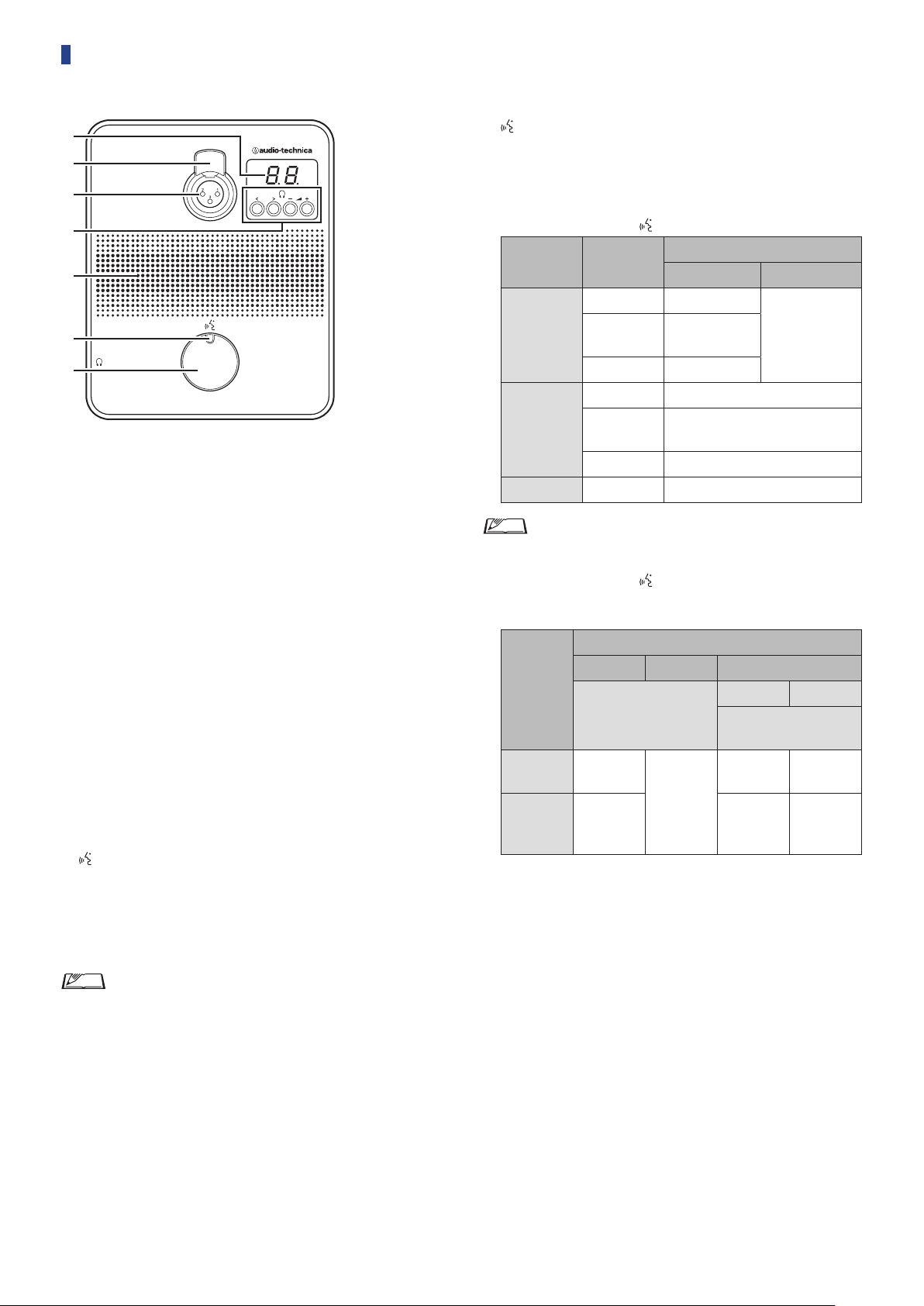
ATUC-50DU
②
③
④
①
⑤
⑦
⑥
Display
①
When changing monitor channel or adjusting the volume level,
the currently set value is displayed.
Microphone release lever
②
Microphone jack
③
Connect a microphone.
• A typical 3-pin XLR type microphone as well as the ATUC-M
series microphone can be connected.
</> Monitor channel selection buttons
④
When operating the </> monitor channel selection buttons, the
currently selected monitor channel is shown on the display ①.
FL: Monitors speech from the floor channel.
01-03: Monitors speech from groups 1 to 3. Speech interpreted
by interpretation units is added to the speech from groups 1 to
3 when INTs are connected on the same system.
–/+ Headphone volume adjustment buttons
When operating the –/+ headphone adjustment buttons, the
current volume level (0 to 20) is shown on the display ①.
Built-in speaker
⑤
Outputs conference audio.
(talk) LED
⑥
Displays DU talk status.
• While talking: lit red
• When requested to talk (in standby mode): blinks green
• When talk request is rejected: blinks green (quickly blinks 4
times)
(talk) button
⑦
Press this button to send a request to talk. Press the button again
to finish talking or cancel the request to talk. DUs designated as
a priority DU can cut other DU speakers short and mute other
DUs by pressing this button.
Operations when the
Conference
mode
Free Talk
Request Talk
Full Remote - - (External control only)
Current state
Talk OFF Talk ON
Requesting to
Talk ON Talk OFF
Talk OFF Request to talk
Requesting to
Talk ON Talk OFF
(talk) button is pressed briefly:
Mic ON Trigger mode
Button Voice
talk
talk
Cancel request
Cancel request
-
(Not acceptable)
• On priority DUs, operations of the priority DUs are same
as in Free Talk Mode regardless of the conference mode.
Operations when the
(talk) button is pressed and
held:
Only for Priority DUs with [Can Cut/Mute] set to on
Mic ON Trigger mode
Current
state
Talk OFF Talk ON
Talk ON Talk OFF
*1 All specified DUs will be in Talk OFF state.
*2 All specified DUs will be in mute state.
Button Voice Button/Vo ice
Press the button
for 2 seconds or less
-
(Not
acceptable)
Cut mode Mute mode
Press and hold the button
for over 2 seconds
Talk
ON(*1)
Talk ON
stays
active(*1)
Talk
ON(*2)
Talk ON
stays
active(*2)
• The LED colors can be changed (➤page 46).
12
Page 13

ATUC-50INT
VOL.
①
②
③
VOL.
A B
④
⑤
⑥
⑦
⑧
Display
• Character on the left: Displays the current monitor channel.
F: Monitors speech from the floor channel (speech from all
meeting participants).
1: Monitors speech from language group 1.
• Digit on the right: Displays the language group (1 to 3)
assigned to the INT output.
When adjusting the volume level, the set value is displayed.
Microphone release lever
Microphone jack
Connect a microphone.
A typical 3-pin XLR type microphone as well as the ATUC-M series
microphone can be connected.
Monitor channel selection button
Switches the speech from the floor channel and the speech from
language group 1 each time it is pressed.
Headphone volume adjustment button
When operating this button, the current volume level (0 to 20) is
shown on the display ①. The volume is adjusted by operating
the
/ buttons
while in this state.
⑥
Operating this button while the volume level is displayed takes
you back to the monitoring channel display.
A / B Interpretation languages selection buttons
(only available in bi-directional interpretation)
This function is only available when bi-directional interpretation
has been selected. (Outgoing language A/Outgoing language B)
Switches the location of the interpretation speech being output
according to the interpretation pattern.
(Talk) LED
Displays INT talk status.
(Talk) button
Press this button to talk. Press the button again to finish talking.
13
Page 14
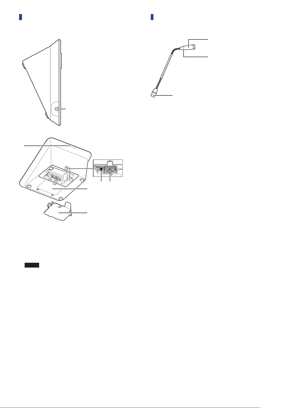
Common to ATUC-50DU/INT
③
①
②
①
②
ATUC-M
Microphone
①
Ring LED
②
Lights red when the microphone is activated.
Blinks red while waiting to talk.
Connector
③
③ ④
⑥
⑤
Headphone jack
①
Speech from the selected monitor channel is output.
Rear LED
②
The LED color can be set for each DU. It is useful when dividing
DUs into groups by color. The LED color can be changed from
Web Remote (
NOTICE
Extension terminal
③
DU/CU connection terminals (
④
Bottom cover
⑤
Covering the terminals protects them from dust and also
prevents cables from becoming unplugged. Therefore, after
connecting cables to each terminal, be sure to attach the bottom
cover.
Serial number
⑥
page 46).
➤
• Color settings cannot be done for INTs. The settings
stay at their default.
page 26)
➤
14
Page 15
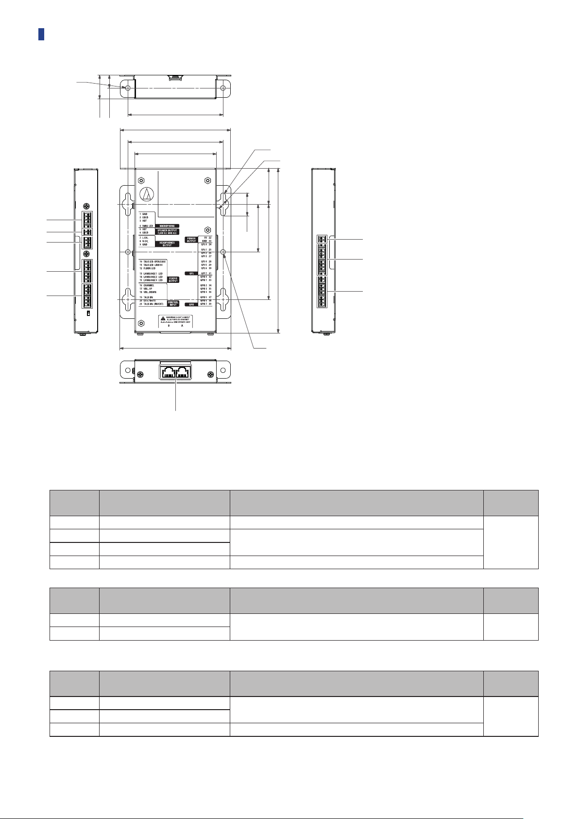
ATUC-50IU
φ5
①
②
③
④
⑤
25
13.5
100
116
100
86
φ5
φ12
38
50
24
173
100
⑥
⑦
⑧
117
φ5
⑨
Because the IU is intended to be embedded in a table, etc., when it is used, the user interfaces, such as displays, operating terminals, and input/
output terminals, can be customized according to their usage environment.
Specifications for the interfaces are as follows.
Microphone input terminal
Pin
number
1 GND Microphone input GND
2 COLD
3 HOT
4 RING LED For controlling ATUC-MIC LED
Speaker output terminal
Pin
number
5 HOT
6 COLD
Signal name Explanation
Microphone input balance
Supplies a phantom power supply of +48 V (possible to toggle on/off )
Signal name Explanation
Speaker output
1.4 W, 8 Ω (impedance over 4 Ω)
Terminal
color
Green
Terminal
color
Green
• We recommend using a shielded wire for the speaker output terminal. The GND shield in this case is connected to the GND pin (9).
Headphone output terminal
Pin
number
7 L ch
9 GND Headphone output GND
Signal name Explanation
Headphone output
15 mW 32 Ω
Terminal
color
Green8 R ch
15
Page 16
Status output terminal
Pin
number
10
11
12 FLOOR LED
13 LANGUAGE1 LED
14 LANGUAGE2 LED
15 LANGUAGE3 LED
TALK LED :
OPEN/CLOSE
TALK LED :
LOW/HI
Signal name Explanation
Talk ON: Close
Talk OFF: Open
Requesting to talk (waiting): blinks
Talk request is rejected: blinks quickly
Terminal for AT8657/LED and U891RCx
Talk ON: +5 V
Talk OFF: 0 V
On/off operations are synchronized with the open/close operations for the
TALK LED pin (10)
Selecting the floor channel on the monitor channel
When selected: Close
When unselected: Open
Selecting group 1 on the monitor channel
When selected: Close
When unselected: Open
Selecting group 2 on the monitor channel
When selected: Close
When unselected: Open
Selecting group 3 on the monitor channel
When selected: Close
When unselected: Open
Terminal
color
Black
Operation input terminal
Pin
number
16 CHANNEL Selecting the monitor's channel
17 VOL. UP
18 VOL. DOWN
19 TALK ON
20 CUT/MUTE
21
Power supply output terminal
TALK ON
(INVERT)
Pin
number
22 5 V Power supply for LED is 5 V
23 GND Power supply GND
Signal name Explanation
Signal name Explanation
Adjusting the headphones' volume
Request to talk
Yes: Close
No: Open
Request to mute/cut microphone
Yes: Close
No: Open
AT8657/LED dedicated terminal
Request to talk
Yes: +5 V
No: 0 V
The function of this pin is the same as that of the TALK ON pin (19)
*When there is a TALK ON or TALK ON (INVERT) request to talk, the
system handles them both as requests to talk.
Terminal
color
Black
Terminal
color
Black
General purpose input terminals (GPI)
Pin
number
24 GPI0 General purpose input terminal 0
25 GPI1 General purpose input terminal 1
26 GPI2 General purpose input terminal 2
27 GPI3 General purpose input terminal 3
28 GPI4 General purpose input terminal 4
29 GPI5 General purpose input terminal 5
30 GPI6 General purpose input terminal 6
31 GPI7 General purpose input terminal 7
Signal name Explanation
Terminal
color
Black
16
Page 17

General purpose output terminals (GPO)
Pin
number
32 GPO0 General purpose output terminal 0
33 GPO1 General purpose output terminal 1
34 GPO2 General purpose output terminal 2
35 GPO3 General purpose output terminal 3
36 GPO4 General purpose output terminal 4
37 GPO5 General purpose output terminal 5
38 GPO6 General purpose output terminal 6
39 GPO7 General purpose output terminal 7
• You can assign functions to the general purpose input/output terminals (GPI and GPO) on the web remote’s settings screen. (➤page 49)
Audio Technica LINK terminal
Connect the Audio Technica products and configure the system.
Signal name Explanation
Terminal
color
Black
NOTICE
• Power is supplied to external devices from the 5 V pin (22); however this pin has a maximum rating of +5 VDC at 100 mA. When you
use this, select a circuit or current limit (resistance value) so that the rating is not exceeded.
• If this is used beyond its ratings, it may cause the product to malfunction, but even more so, it may cause fires or unforeseen
accidents.
17
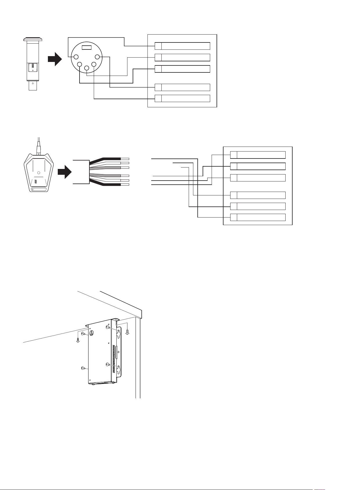
Page 18
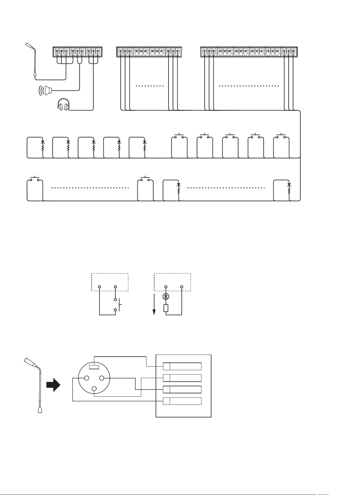
Example of a user interface connection
1 2 3 4 5 6 7 8 9
TALK LED
OPEN/CLOSE
22 10 22 12 22 13 22 14 22 15
GPI 0 GPI 7
24 23 31 23
FLOOR
LED
LANGUAGE 1
LED
LANGUAGE 2
LED
LANGUAGE 3
LED
21 22 23 24 25 26 27 28 29 30 31 32 33 34 35 36 37 38 392019181716151413121110
CHANNEL VOL. UP VOL. DOWN TALK ON CUT/MUTE
16 23 17 23 18 23 19 23 20 23
GPO 0
22 32
GPO 7
22 39
IN
When using with the ATUC-MIC
XLR
XLR
Receptacle
Receptacle
FG
3
Input pin Output pin
入力ピン
(23pin GND) (22pin 5V)
最大
Max.
7 mA
7mA
出力ピン
IN
ATUC-50IU
GND1
21
COLD2
HOT3
RING LED4
18
Page 19
When using with the AT8657/LED
ATUC-50IU
51
2 4
3
When using with the U891RCx
GND1
COLD2
HOT3
TALK LED: LOW/HI11
TALK ON (INVERT)21
BK: GND
WH: LED CONTROL
BL: CONTACT CLOSURE
RD: COLD
YL: HOT
SH: GND
ATUC-50IU
GND1
COLD2
HOT3
TALK LED: LOW/HI11
TALK ON19
• Do the following settings for the U891RCx.
SW.FUNCTION: MOM. ON
CONTROL: LED Remote
Mounting an IU
• When securing in two directions
Align the IU with the edge of a table, etc., and then fasten it with screws.
GND23
19
Page 20
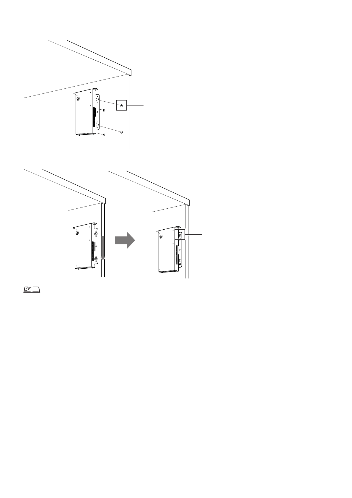
• When securing on only one side
Leave about 2 mm of the screws out when you fasten them to the table, and then hang the IU on them. Slide the IU downward, and then tighten
the screws to secure the IU.
Suspend screws about 2 mm
Tighten screws securely
• You can also mount the IU upside-down or sideways. When mounting, fasten at a minimum of two places with screws.
20
Page 21
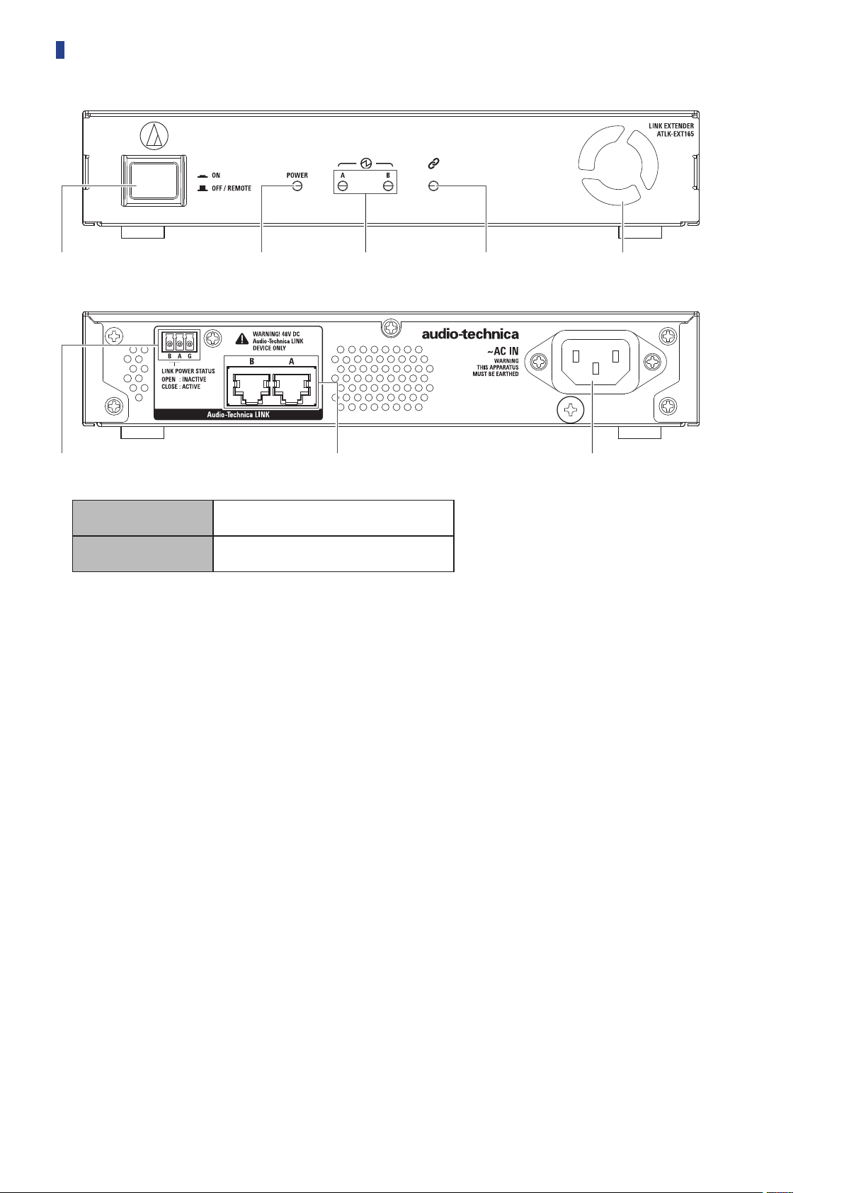
ATLK-EXT165
①
⑥ ⑦ ⑧
Mode switch
Remote mode
Standalone mode
Power indicator
Audio Technica LINK Device indicator
Indicates the connection status of devices that support Audio Technica LINK.
• Connected: Lit
• Unconnected: Unlit
Data indicator
• Establishing link (data not transmitted): Lit
• Transmitting data: Blinking
• No link: Unlit
Cooling fan
Audio Technica LINK POWER STATUS output terminal
Open: Power inactive
Close: Power active
Audio-Technica LINK A/B terminals
• RJ-45
• Use to connect the devices that support Audio-Technica LINK.
AC inlet (AC IN)
Connect the supplied AC power cord.
② ③ ④ ⑤
This mode allows the CU to automatically start
the unit.
This mode allows you to operate the EXT by
itself.
21
Page 22

Changing settings from ATUC-50CU
You can change CU settings by selecting “Set” on the HOME screen
of the CU display. Changeable items are as follows.
For more detailed settings, or for individual DU/IU/INT settings,
use Web Remote.
• After changing the network setting item(s), restart the
CU to enable the setting values.
Set Menu Items
[1] System Setting (
37)
01 Device Name
02 Link Port Set
03 CU Link Mode
04 CU Error Notice
05 IP Setting
01 IP Config Mode
02 IP Address
03 Subnet Mask
04 Gateway Address
06 Allow Discovery
07 IP Ctrl Setting
01 IP Ctrl Port No
02 IP Ctrl Ntfy
03 Audio Level Ntfy
04 M-cast Adrs
05 M-cast Port No
08 Auto Mode Change
01 Auto Mode Change
02 Hold Time(Err)
09 NTP Setting
01 NTP
02 NTP Adrs
03 NTP Port
04 Time Zone
05 DST
06 DST Start Date
07 DST Start Time
08 DST End Date
09 DST End Time
10 Login Password
01 Admin.Pwd.Login
02 Admin.Password
03 Opr.Pwd.Login
04 Opr.Password
11 Reset All Dflt.
[2] System Info (
54)
01 Name
02 Serial Number
03 FW Version
04 IP Config Mode
05 IP Address
06 Subnet Mask
07 Gateway Address
08 Mac Address
09 Allow Discovery
10 IP Ctrl Port No
11 IP Ctrl Ntfy
12 Audio Level Ntfy
13 M-cast Adrs
14 M-cast Port No
15 NTP
16 NTP Adrs
17 NTP Port
page
➤
page
➤
ATUC-50CU
CU A/B, DU C/D
Primar y, Extension Pass Thru,
Extension Last Unit
On, Off
Auto, Static
0.0.0.0 - 255.255.255.255
0.0.0.0 - 255.255.255.255
0.0.0.0 - 255.255.255.255
On, Off
00001 - 65535
On, Off
On, Off
0.0.0.0 - 255.255.255.255
00001 - 65535
On, Off
20, 30, 40 seconds
On, Off
0.0.0.0 - 255.255.255.255
00001 - 65535
UTC –12:00 to +14:00
On, Off
1/1 - 12/31
0:00 - 23:00
1/1 - 12/31
0:00 - 23:00
On, Off
Displays password
On, Off
Displays password
Displays current settings
18 Time Zone
19 CU Link Status
20 CU Link Mode
21 No.ofExtensionCU
22 Total No.of DU
23 Total No.of IU
24 Total No.of INT
[3] Audio Setting (
page
➤
42)
01 MIC/LINE Input 1
01 Input Type
02 Input Gain
03 Level
04 Phantom Power
05 Mix to Floor
02 MIC/LINE Input 2
01 Input Type
02 Input Gain
03 Level
04 Phantom Power
05 Mix to Floor
03 AUX Input
01 Level
02 Mix to Floor
04 DU SP Output Lvl
05 DU Floor Lock
06 VoiceDetectSens
07 Auto to Mic2 In
[4] Recorder Setting (
53)
01 Rec Format
02 RecordingQuality
03 No.of Rec CH
04 Rec Source CH1
05 Rec Source CH2
06 Rec Source CH3
07 Rec Source CH4
08 Auto Track
09 Filename Prefix
[5] Conference Mode
(
page 45)
➤
01 Conference Mode
02 NOM
03 Auto Mic Off
04 Override Mode
05 Max Queue
page
➤
Mic, Line +4dBu, Line 0dBV
–60dB to –16dB
–∞, –120 to +10dB
On, Off
On, Off
Mic, Line +4dBu, Line 0dBV
–60dB to –16dB
–∞, –120 to +10dB
On, Off
On, Off
–∞, –120 to +10dB
On, Off
0 - 20
On, Off
–5, –4, –3, –2, –1, 0, 1, 2, 3, 4, 5
On, Off
WAV, MP3
64, 128, 192, 256, 320kbps
1 to 4 (WAV), 1 to 2 (MP3)
Floor, Group 0, Group 1,
Group2, Group 3, Language 1,
Language 2, Language 3,
RemoteLang. 1, Remote Lang. 2,
Mic/Line 1, Mic/Line 2,
Mic/Line 1&2 Mix
Floor, Group 0, Group 1,
Group2, Group 3, Language 1,
Language 2, Language 3,
RemoteLang. 1, Remote Lang. 2,
Mic/Line 1, Mic/Line 2,
Mic/Line 1&2 Mix
Floor, Group 0, Group 1,
Group2, Group 3, Language 1,
Language 2, Language 3,
RemoteLang. 1, Remote Lang. 2,
Mic/Line 1, Mic/Line 2,
Mic/Line 1&2 Mix
Floor, Group 0, Group 1,
Group2, Group 3, Language 1,
Language 2, Language 3,
RemoteLang. 1, Remote Lang. 2,
Mic/Line 1, Mic/Line 2,
Mic/Line 1&2 Mix
Off, 15, 30 min, 1, 2 hour
Displays filename prefix
Free Talk, Request Talk, Full
Remote
1 to 10
5 to 60sec ,Off
No Override, FIFO, LIFO
(depending on Conference
Mode)
0-150
22
Page 23

06 MicON Trigger
07 MicON Hold Time
08 Interrupt Option
[6] Logging (
01 Logging
02 Destination
[7] Presets (
01 Recall Presets
02 Save Presets
03 Import Presets
04 Export Presets
05 Boot Up Preset
page 54)
➤
page 54)
➤
All Button, All Voice, Individual
1.0 to 10.0 seconds
Cut, Mute
On, Off
Internal, USB
Recalls presets
Saves presets
Imports presets
Exports presets
Calls presets at boot up
Entering letters
For example, when entering letters from [4]
09Filename Prefix
Rotate the jog dial to select a letter.
1
You can use the following characters.
Password
(1)
A to Z, a to z, 1 to 9, 0
Device Name
(2)
A to Z, a to z, 1 to 9, 0, ! # $ ‘ ( ) * + , - . : ; < = > ? @ `, (space)
Filename Prefix
(3)
A to Z, a to z, 1 to 9, 0, ! # $ ‘ ( ) + , - . ; = ? @ `, (space)
Press the ENTER button to enter the selected
2
, follow the procedure below.
letter.
The cursor moves to the right.
Repeat steps 1 and 2 to enter desired text.
3
To delete characters you have just entered, follow the procedure
below.
• To move the cursor to the character you want to edit:
(1) While pressing and holding the BACK button, rotate the
jog dial to move the cursor.
(2) Release the BACK button.
• To delete characters you have just entered:
(1) Move the cursor to the character you want to delete.
(2) While pressing and holding the BACK button, press the
ENTER button.
The character at the current cursor position will be
deleted.
Recorder Setting
→
• When the cursor flashes in “_” state at the end of the
text, the character just before the cursor will be deleted.
• To change characters you have just entered:
(1) Move the cursor to the character you want to edit.
(2) Rotate the jog dial to select the desired character.
• To finish editing:
(1) When the cursor is in “■” blinking state, press the
ENTER button.
When editing ends, the cursor will move to the end of the
text and “_” will blink.
To enter the text, when the cursor is in the “_”
4
blinking state, press the ENTER button.
Displays
Completed!
followed by the file name.
23
Page 24
Overview of the Interpretation Unit
"Hello"
"Thank you"
" こんにちは "
" ありがとう "
B
A
(ATUC-50INT)
• Up to 6 interpretation units can be connected.
• The maximum number of DU/IU/INT connections is 300 (when
three CUs are linked).
• INTs can only be connected to the primary CU. They cannot be
connected to extension CUs.
Digital Conference System ATUC-50 with the additional
Interpretation Unit ATUC-50INT enables the following three types,
(1) to (3), of interpretation.
This section explains a brief overview of operations assuming that
you have set the interpretation languages as in the following table.
Audio Group 1 English
Language Name
Audio Group 2 Japanese
Audio Group 3 French
(1) Interpretation using two languages (2 Languages)
• While in the 2 Languages interpretation mode, you can select from
three interpretation patterns (see table below).
• For instance, when the interpretation pattern “English → Japanese”
is set, “F” appears as the character on the left in the display ①, and
“2” appears as the digit on the right. At this time, the speech from
the floor channel is heard through the monitor channel.
Additionally, interpreted speech that is input from the microphone
of the INT is output to Audio Group 2 (the Japanese group).
• When the bi-directional interpretation pattern is selected, the
interpretation system is established with just this INT1. Pressing
the interpretation languages selection button ⑥ switches the
interpretation patterns between “Japanese → English (Outgoing
language A)” and “English → Japanese (Outgoing language B)”,
simultaneously switch the interpreted speech being output.
Whichever interpretation pattern you selected, “Japanese → English
(Outgoing language A)” or “English → Japanese (Outgoing
language B)”, it is not saved. When the system is started, the
interpretation pattern is “Japanese → English (Outgoing language
A)”.
Interpreted speech
Monitored speech
Audio Group 2
Japanese
Audio Group 1
English
Interpreted speech
Monitored speech
Moni
-
Interpretation
pattern
English ↔
Japanese
English →
Japanese
Japanese →
English
* Interpreters can do a switch operation to monitor the audio of
language group 1 (key language)
Inter-
preter
A + B
speech
B Japanese 2
A English 1
Character
tored
onthe
left
Floor* F*
Outputdestination
group
Outgoing
language A
Outgoing
language B
Digit
onthe
right
English 1
Japanese
2
24
Page 25
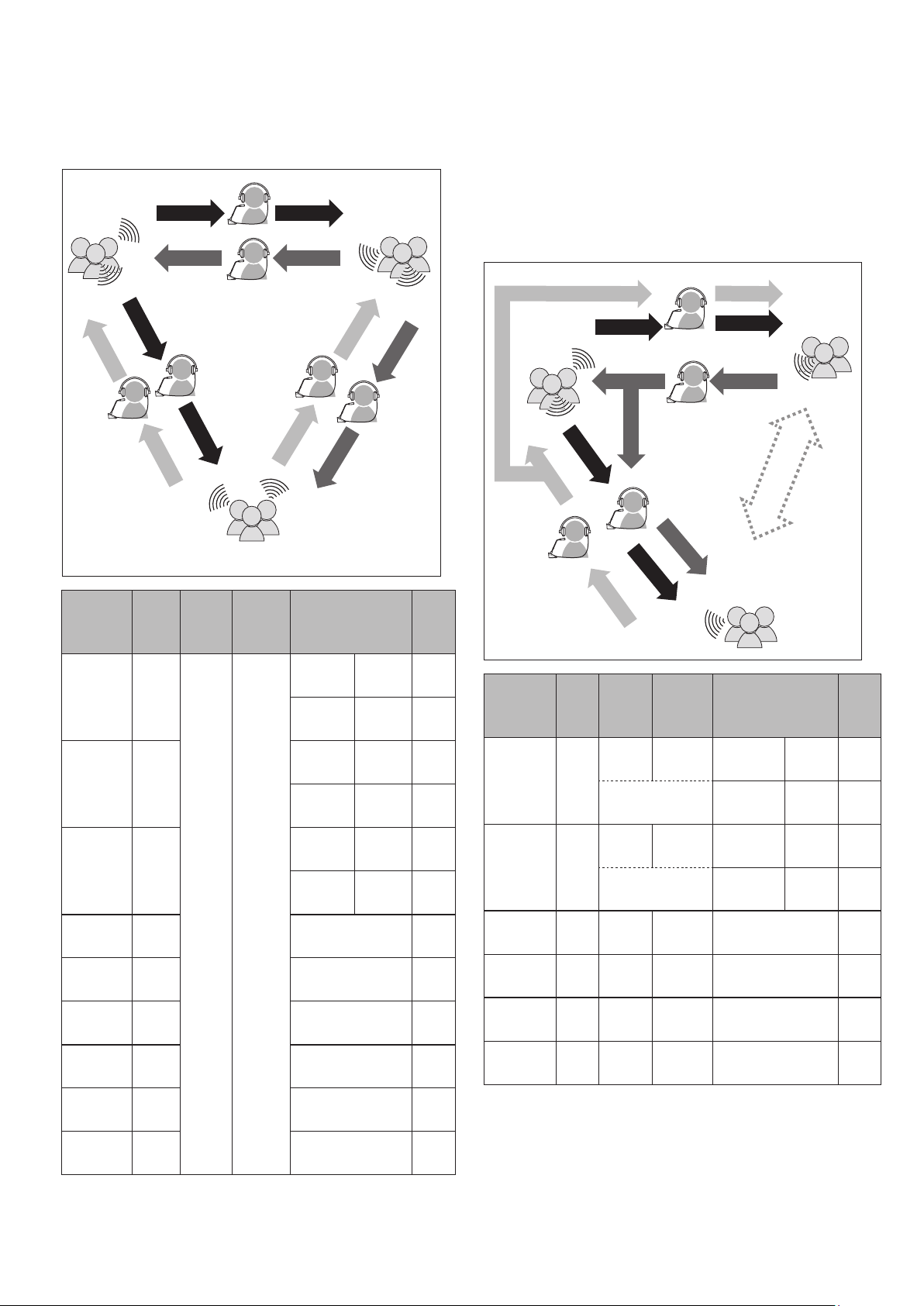
(2) Interpretation using three languages (3 Languages)
• While in the 3 Languages interpretation mode, you can select from
nine interpretation patterns (see table below).
• Although there are three ways to do combinations within 2
Languages, the basic operations are the same as those for 2
Languages interpretation.
Audio Group 1
English
Interpreted
speech
"Yes"
Interpreta-
tion
pattern
English ↔
Japanese
English ↔
French
Japanese ↔
French
Monitored
"Hello"
speech
C
Monitored
speech
"Oui"
Inter-
preter
A + B
C + D
E + F
"Hello"
Monitored
speech
Interpreted
speech
"Thank you"
D
"Bonjour"
Interpreted
speech
Moni-
tored
speech
Audio Group 3
Character
B
A
French
onthe
left
" こんにちは "
Interpreted
speech
Monitored
speech
" ありがとう "
" はい "
Interpreted
E
"Oui"
speech
Monitored
speech
Interpreted
"Merci"
Outputdestination
group
Outgoing
language A
Outgoing
language B
Outgoing
language A
Outgoing
language B
Outgoing
language A
Outgoing
language B
Audio Group 2
Japanese
speech
speech
Monitored
" ありがとう "
F
English 1
Japanese 2
English 1
French 3
Japanese 2
French 3
Digit
onthe
right
Floor* F*
English →
Japanese
Japanese →
English
English →
French
French →
English
Japanese →
French
French →
Japanese
B Japanese 2
A English 1
D French 3
C English 1
F French 3
E Japanese 2
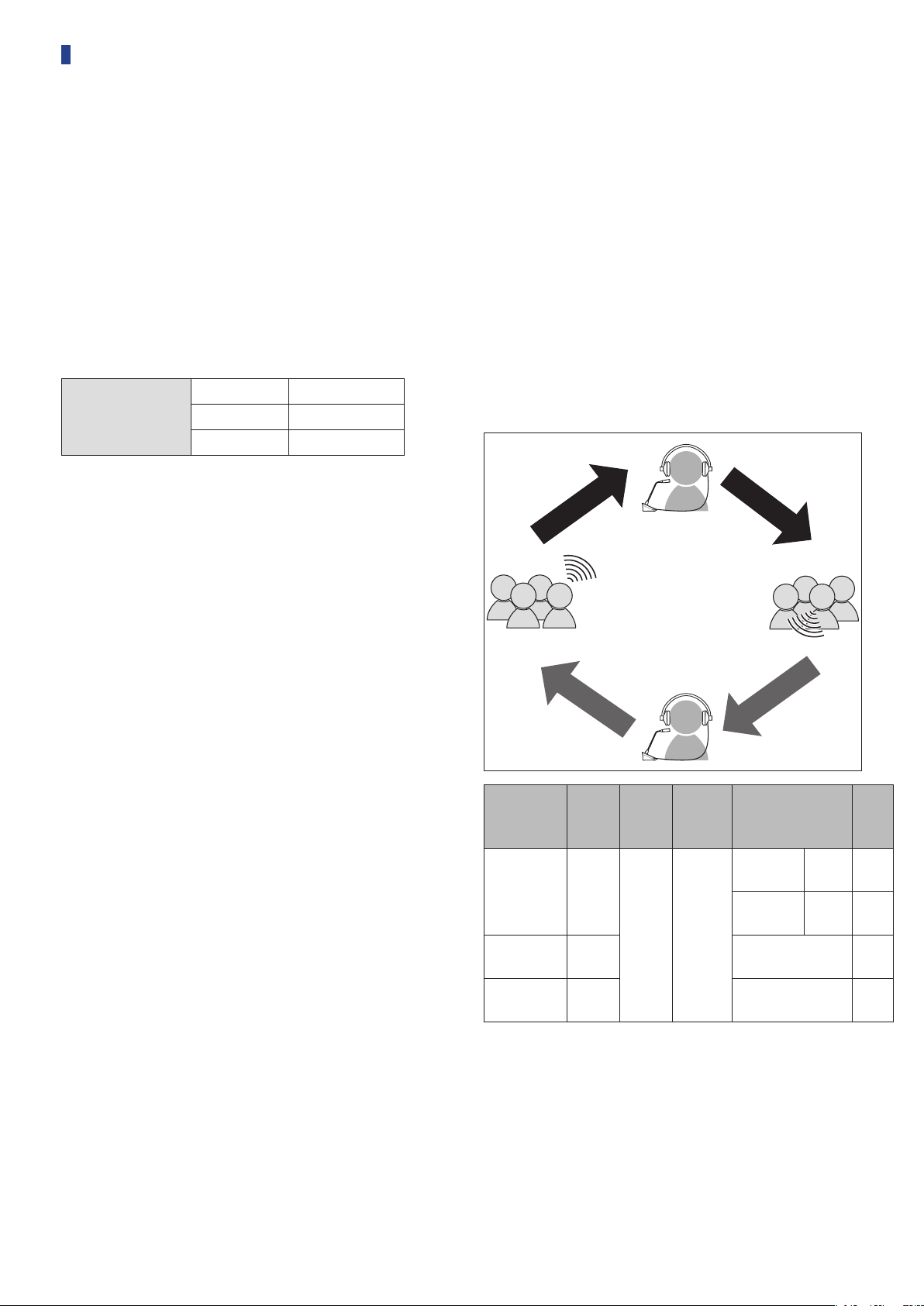
• Out of the three languages, the language of Audio Group 1 is used
as the key language (in this case it is English), and relay
interpretation is possible. (diagram below)
• When interpreting from French to Japanese, for example,
Interpreter C first interprets “French → English”. Interpreter B
switches the monitor channel to the key language “1”, listens to the
English interpretation from interpreter C, and then interprets
“English → Japanese”.
• Other than that, the basic operations are the same as those for 2
languages.
" はい "
Interpreted
speech
Interpreted
speech
" こんにちは "
" ありがとう "
Monitored
A
speech
Audio Group 3
French
Outputdestination
Outgoing
language A
Outgoing
language B
Outgoing
language A
Outgoing
language B
group
Audio Group 2
Japanese
Interpretation
between these
languages is
unnecessary.
Digit
onthe
right
English 1
Japanese 2
English 1
French 3
Audio Group 1
English
(Key language)
Interpreted
speech
"Yes"
Interpreta-
tionpattern
English ↔
Japanese
English ↔
French
English →
Japanese
Japanese →
English
English →
French
French →
English
B
Monitored
speech
"Hello"
"Thank you"
Interpreted
speech
"Hello"
Monitored
speech
D
"Merci"
C
Monitored
speech
"Oui"
Inter-
preter
C + D
Moni-
tored
speech
Floor/
English
A + B
Floor/
English
B English 1 Japanese 2
A Floor F English 1
D English 1 French 3
C Floor F English 1
Interpreted
speech
"Bonjour"
Interpreted
speech
Character
onthe
left
F/1
(switched by
interpreter)
F/1
(switched by
interpreter)
* Interpreters can do a switch operation to monitor the audio of
language group 1 (key language)
25
Page 26
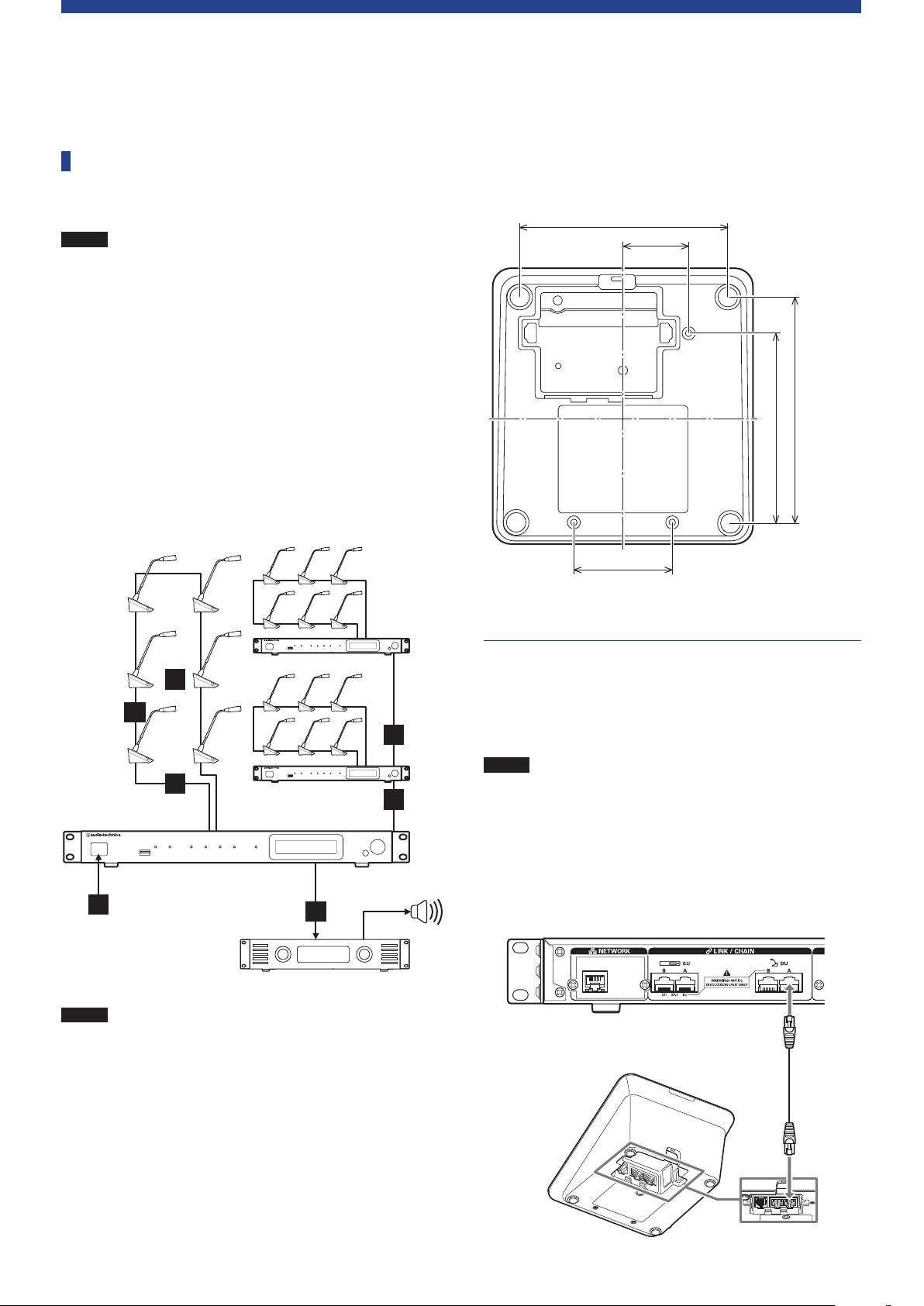
System Connections and Configuration
Connecting devices
NOTICE
Entire system connection diagram (1)
Refer also to the entire system connection diagram (2) (
31)
• Do not plug in the supplied AC power cord until all other
connections have been completed.
• Insert the plugs all the way in. Loose connections may
cause malfunctions or noise.
• Check the plug orientations.
• Refer also to the instruction manuals supplied with the
external devices.
• Although connecting the CUs, DUs, and INTs are
described here, because basic IU connections are the
same as those for DUs, refer to connecting the DUs when
connecting IUs.
page
➤
When securing a DU/INT to a desk or table, use the screw holes
(3holes) on the bottom side of the DU/INT (screw: M3, P=0.5,
within 6mm from the bottom side to the tip of the screw).
95
30
87
(103.5)
45
NOTICE
3
2
1
5
Amplifier
• Use straight cables. (Shielded cables with conductor size
of 24AWG or higher in diameter are recommended.)
• Using flat type cables or unshielded cables may cause
noise and affect other devices.
• Be sure to establish a ground connection.
4
1
1
Speaker
Connecting the DUs/INTs to the CU
1
Place the CU(s) and DUs/INTs.
1
NOTICE
2
• Place the units on a flat surface or install in a rack.
Dropping a unit may cause damage to the unit and/or
personal injury.
• When installing the CU in a rack, read the precautions in
advance (
page 5).
➤
Connect the DU/INT(s) to the DU CHAIN A/B
terminal(s).
Ethernetcable
26
Page 27
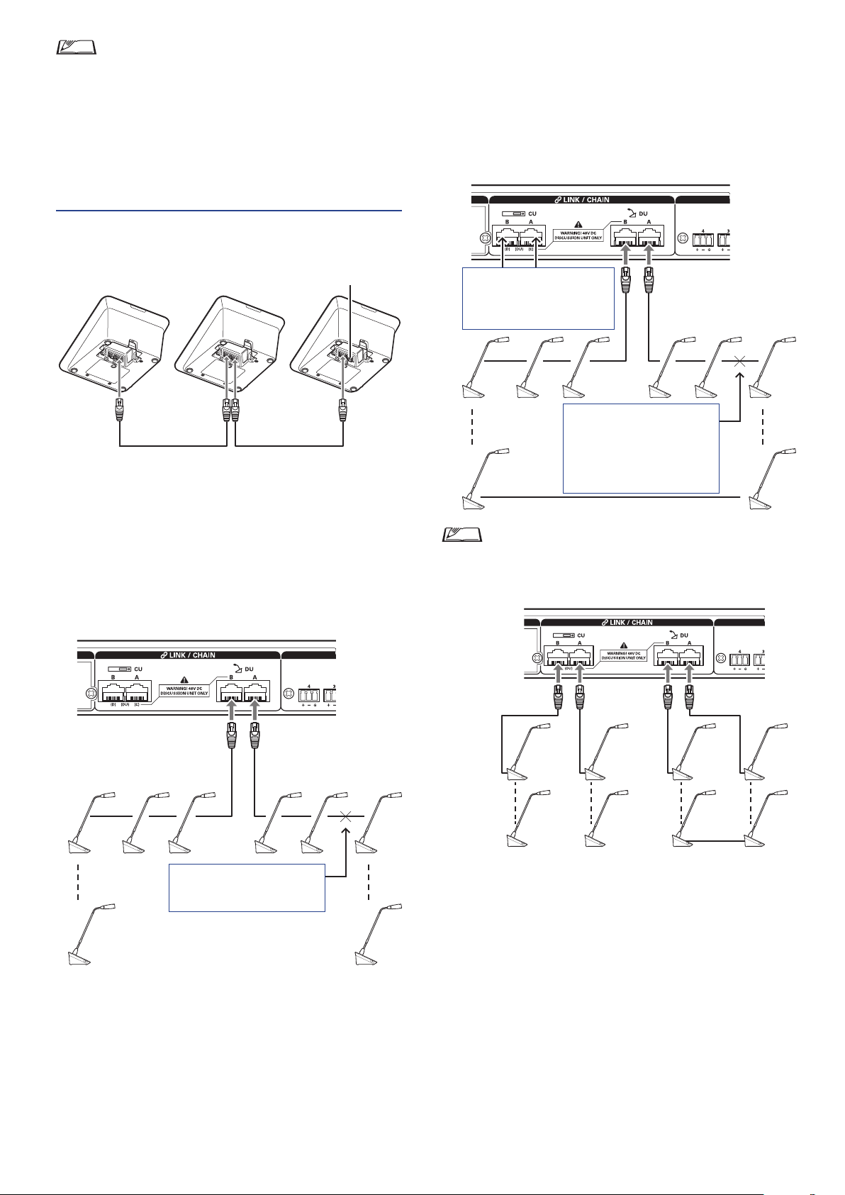
• Remove the DU/INT bottom cover to connect the
Ethernet cables. When removing the bottom cover, pinch
together the latches on both sides.
• On the DU/INT, the Ethernet cable may be connected to
the left or right DU/CU connection terminal because the
DU/INT does not distinguish between DU and CU
connection terminals.
Connecting the DUs/INTs together
2
Ring connection:
Connect as many DUs/INTs as necessary to each of the DU
CHAIN A/B terminals and then connect together the 2 DUs/
INTs on both ends of the chain so as to form a ring. Even if a
connection failure occurs somewhere in the ring, since the
connection is recognized as 2 daisy-chains using the DU CHAIN
A/B terminals, the influence of the failure can be minimized and
you can carry on conference control.
To ATUC-50CU
Ethernet cable
Connect the DUs/INTs according to the
1
Ethernet cable
installation environment and operation method.
Daisy-chain connection:
Connect the DUs/INTs in a series to the DU CHAIN A/B (C/
D) terminals. Compared to ring connection, daisy-chain
connection enables the DUs/INTs to be placed even farther
from the CU.
One more ring connection can
be made by configuring these
terminals as the DU CHAIN
terminals.
Even if a connection failure
occurs, since the connection is
recognized as 2 daisy-chains
using the DU CHAIN A/B
terminals, you can carry on
conference control.
• Combining different connection types is also possible,
such as a ring connection using the DU CHAIN A/B
terminals and daisy-chain connections using the DU
CHAIN C/D terminals.
End of the chain
If a connection failure occurs
here, the connection to the end
of the chain will be defunct.
End of the chain
Daisy-chain connection Ring connection
Expand the system with EXT.
2
By adding EXT to the system, you can increase the number of DU/
INT/IU connections and extend the distance of the total extension
length of the connecting cable (LAN cable).
For instance, you can connect a total of 100 DUs/INTs/IUs, 50
units on either terminal, by connecting an EXT near the B terminal
when using a daisy chain connection on the DU CHAIN A/B
terminals.
27
Page 28

Maximum number of connections for each terminal/each CU in Standalone mode
Maximum number of terminal
connections in a DU CHAIN
A B C D Total
Daisy Chain
Ring
* Up to 100 units can be connected to each CU. Set up your system so that the total number of units connected to each DU CHAIN terminal is 100 or
fewer.
50 50 25 25 100*
50 25 75
Maximum number of connections for each terminal/each CU when using 3 CU links
ATUC-50CU Primary ATUC-50CU Extension *max 2pcs
Maximum number of
Daisy Chain
Ring
terminal connections
in a DU CHAIN
A B Total A B Total
50 50 100 50 50 100 200 300
50 50 50 50 100 150
Maximum number of terminal
connections in a DU CHAIN
CU x 2
Total
System
Total
NOTICE
• Up to 6 INTs can be connected to the primary CU.
28
Page 29
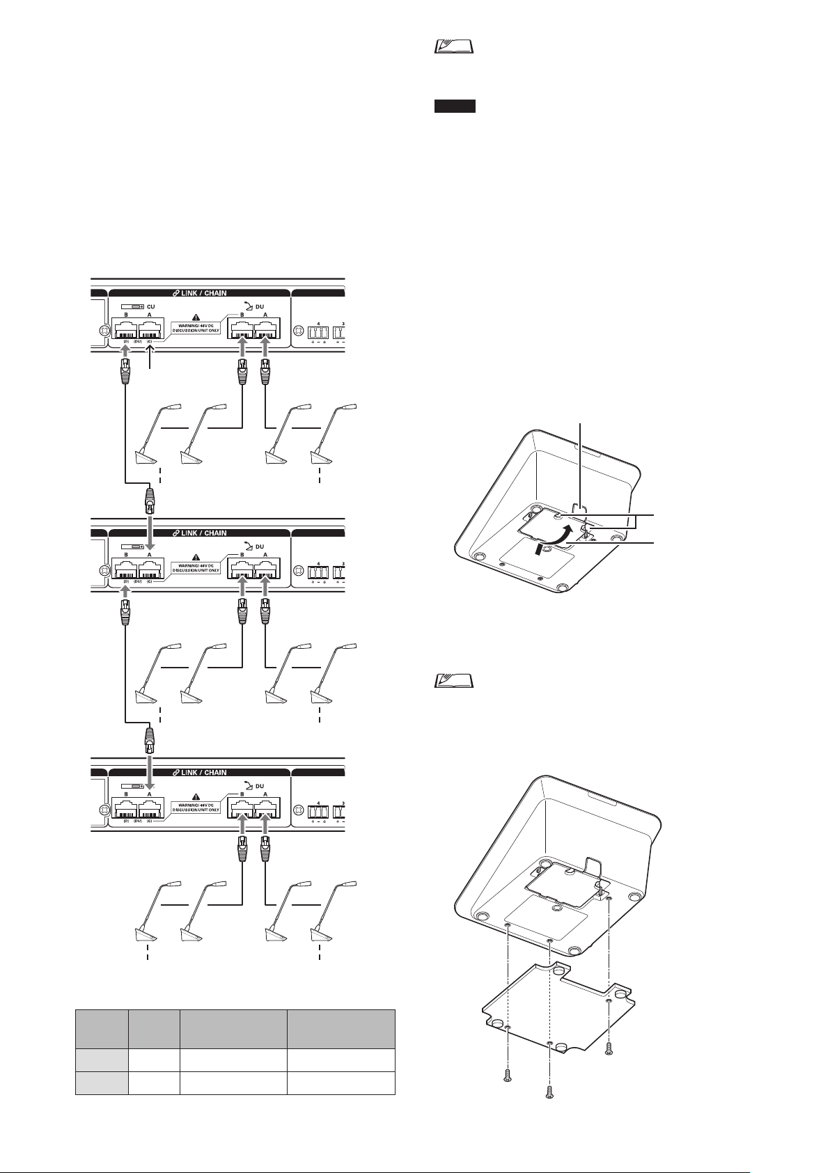
CU Link connection:
②
①
Up to 3 CUs can be cascaded (cascade CUs using the CU LINK
A/B terminals as shown below). Set one of the CUs as the
primary unit.
Since up to 100 DUs/INTs can be connected to each CU, if you
use 3 CUs, up to 300 DUs/INTs can be connected in total.
Follow the procedure below to cascade CUs.
Connect the CU LINK A terminal on the 1st extension CU to
①
the CU LINK B terminal on the primary CU.
When cascading 2 extension CUs, connect the CU LINK A
②
terminal on the 2nd extension CU to the CU LINK B terminal
on the 1st extension CU.
Primary CU
Terminal A is
not used.
①
• You can either daisy-chain (
27) DUs/INTs to each CU.
NOTICE
3
• When using only one CU without a CU Link connection,
be sure to set [CU Link Setting] to [Primary]. If [CU
Link Setting] is set to [Extension], we do not assume
responsibility for any unexpected consequences that may
occur.
• Up to 6 INTs can be connected to the primary CU. They
cannot be connected to extension CUs.
Attach the bottom cover to the DU/INT.
After connecting the Ethernet cables to the DUs/INTs, attach
the bottom cover to each DU/INT.
• The Ethernet cable is fixed securely between the DU/INT and
the bottom cover. This helps reduce the load that the DU/
INT places on the Ethernet cables.
• To lead the cable out to the rear side, use the through hole
To lead the cable out to the bottom side, use the through holes
.
②
page 27) or ring (
➤
➤
page
.
①
1st extension
CU
②
2nd extension
CU
up to 100 units
up to 100 units
(INTs cannot be connected)
Bottom cover
Attach the optional bottom weight to the DUs/
4
INTs.
• When using DUs/INTs that are not secured to desktops
or tabletops, it is recommended to use the optional
bottom weight (330g) for secure placement.
• To purchase the optional accessories, contact our sales
team.
up to 100 units
(INTs cannot be connected)
Primary/Extension (
Primary
CU
2-CU Link [Primary] [Extension Last Unit] -
3-CU Link [Primary] [Extension Pass Through] [Extension Last Unit]
CU Link Mode
1st extension CU 2nd extension CU
):
29
Page 30
Connecting the microphone ATUC‑M
3
to the DU/INT
Connect the ATUC‑M to the microphone jack on
1
the DU/INT.
ATUC-M
ATUC-50DU/INT
NOTICE
5
• When connecting external devices to IN/OUT terminals,
do so after cutting the phantom power supply of the
external devices. If you leave the phantom power supply
on, it may cause unexpected malfunctions.
• When connecting external devices, refer also to the
instruction manuals supplied with them.
Turning on the CU and testing DU
operations
After checking that all the connections from steps 1 to 4 have
been done properly, follow the procedure below to turn on the
power of the CU.
Check that all the PA devices such as an amplifier
1
and mixer are off.
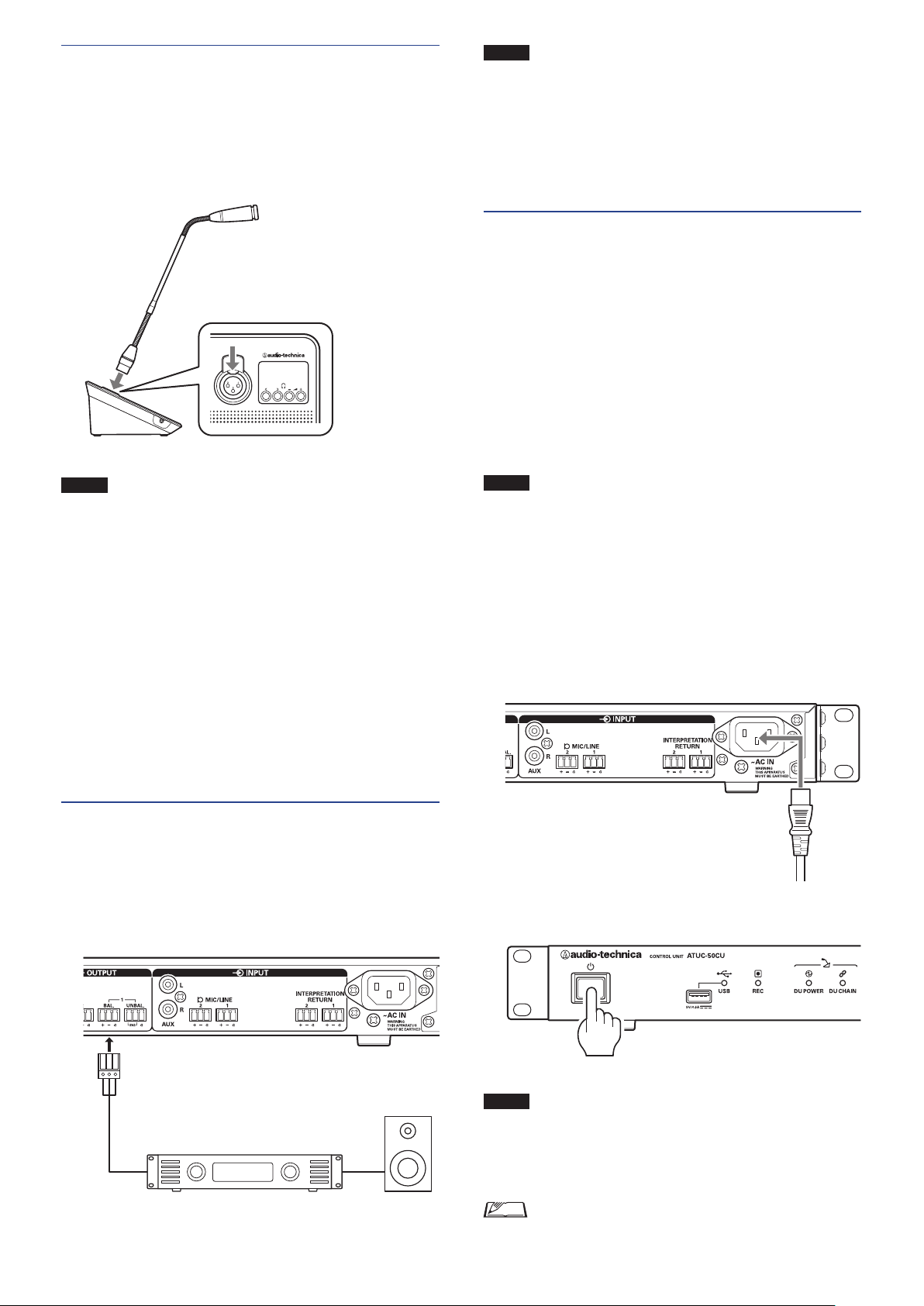
Connect the supplied AC power cord to the CU.
2
NOTICE
4
1
• Insert the ATUC-M connector in until you hear a
clicking sound.
• Do not attempt to lift up the DU/INT by grabbing the
ATUC-M. Be sure to hold the main body of the DU/INT
when lifting it up.
• Slowly bend or extend the flexible part of the ATUC-M.
Do not apply excessive force to the ATUC-M when
bending it.
• When disconnecting the ATUC-M from the DU/INT,
securely hold the connector while pressing down the
microphone release lever and then remove the ATUC-M.
• Before connecting/disconnecting the ATUC-M, be sure
to turn off the power. If you do not turn off the power,
malfunction may occur.
Connecting an amplifier
Connect an amplifier to the OUTPUT BAL.
terminal.
Connect an amplifier to amplify sound.
Connect a speaker via the amplifier.
NOTICE
3
• Be sure to use the supplied AC power cord. Using an AC
power cord other than the supplied one may cause
problems such as damage to the CU, which can be very
dangerous.
• Be sure to connect the AC power cord into a properly
grounded wall outlet. Improper grounding can cause
electrical shock.
• Be sure that the CU is securely grounded to a single
ground point. Grounding to multiple ground points can
cause ground loops, resulting in noise generation such as
a humming noise
Press the power button.
OUTPUT BAL. terminal
Amplifier Speaker
30
NOTICE
• When one or two extension CUs are connected to the
system, turn on the power of the primary CU and
extension CU(s) at the same time. If the time period
between each power-on time is significantly long, a
successful CU Link may not be established.
• Configure the network setting from the CU (
as necessary.
page 22)
➤
Page 31
After the CU starts up, press the
4
each DU to confirm operation.
(talk) button of
NOTICE
5
• When the DUs are placed close to each other, excessively
raising the volume of the DU speakers may cause
howling. In such a case, move the DUs farther away from
each other or decrease the volume.
After checking that the DUs are operating, turn
off the CU before proceeding to the next step for
connecting the CU to a network device.
NOTICE
• If the power of the amplifier is on, first turn off the
power of the amplifier.
Entire system connection diagram (2)
Web Remote
7
Tablet
Web Remote
Control
Computer
7
Switching hub
AP
Router
6
Control
NETWORK
terminal
Ethernet cable
Switching hub
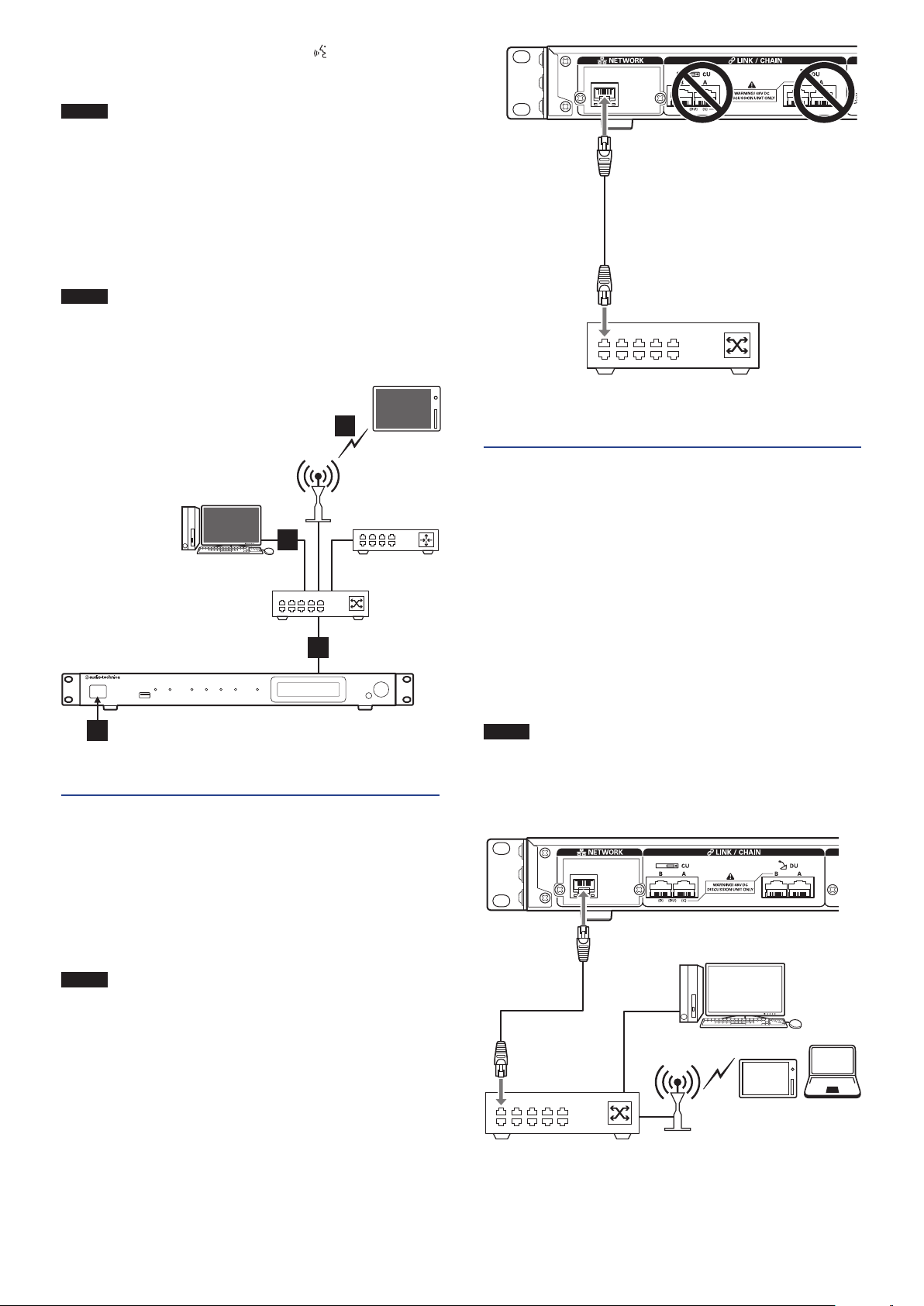
Connecting a computer or mobile
7
device to a network
About network settings
• If there is a DHCP server running on the network, the CU
automatically configures network settings including the IP
address.
• If there is no DHCP server running on the network, manually
configure network settings including the IP address from the Set
System Setting
Menu →
• When configuring settings manually, inquire with the network
manager regarding setting items.
(
page 10).
➤
5
Connecting to a network
6
Configure the detailed conference system settings via Web Remote
by connecting the CU to a network (
Use an Ethernet cable to connect the CU to a
1
page 33).
➤
switching hub via the NETWORK terminal.
NOTICE
• Be careful NOT to connect the Ethernet cable from your
network device to the CU LINK terminal or DU CHAIN
terminal. This can cause damage to the connected device.
NOTICE
Switching hub
• We decline any and all responsibility for communication
errors and failures regarding your network environment
and external devices.
• Disable the firewall setting on your computer. Otherwise,
“Locate” will not recognize the CU.
NETWORK
terminal
Ethernet cable
Computer
Mobile device
AP
31
Page 32

To connect the CU directly to the your Windows PC/Mac
using an Ethernet cable
If your computer is equipped with an NIC (Network Interface
Card), you can also connect the CU directly to the computer using
an Ethernet cable.
NOTICE
1
• Be careful NOT to connect the Ethernet cable from the
computer to the CU LINK terminal or DU CHAIN
terminal. This can cause damage to the computer.
Connect an Ethernet cable (straight) to the
NETWORK terminal on the CU and Ethernet
terminal on a computer.
In the network settings on your Windows PC/Mac,
2
select “Obtain an IP address automatically” on
your Windows PC, or “Using DHCP” on your Mac,
and then save the settings.
(
page 10).
➤
System
Start up the CU and from the Set Menu →
3
Info
Press the BACK button to close the Set Menu.
4
IP Config Mode
→
• After changing the network setting item(s), restart the
CU to enable the setting values.
Since there is no DHCP server, an IP address is automatically
assigned to the Windows PC/Mac and the CU using the API PA
(Automatic Private IP Addressing) feature.
, select
Auto
32
Page 33

Preparing to use Web Remote
What is Web Remote?
For iOS users:
Search from App Store and install “Locate”.
Web Remote is a web application to control this system.
Using Web Remote enables you to remotely perform the following
operations from a computer or mobile device (hereinafter, control
device):
• Preparing for conferences
• Operating and controlling conferences
• Configuring detailed settings
After connecting the CU to the control device, download “Locate”.
Using “Locate” enables you to simply access Web Remote (
35) without typing the IP address of the ATUC-50CU installed.
• You can also start up Web Remote without using
“Locate” (
Operating Environment for Web Remote and “Locate”
• Microsoft Windows 7 or later
• Apple OS X10.11 El Capitan or later
• Android OS5.0 or later
• iOS9 or later
Recommended web browser for Web Remote
• Microsoft Internet Explorer 11 (Windows)
• Google Chrome ver. 57 or later (Windows and Android)
• Mozilla Firefox ver. 52 or later (Windows)
• Safari 10 or later (OS X and iOS)
NOTICE
• Up to 3 control devices can simultaneously log in to Web
Remote.
When 2 web browsers are running on a control device,
Web Remote counts the web browsers as 2 separate
devices.
• When you have finished with Web Remote, be sure to log
out of Web Remote before closing the web browser
window.
If you simply close the window without logging out, you
will remain logged in to Web Remote for 5 minutes until
the session times out.
page 35).
➤
page
➤
Proceed to step 4.
For Android users:
Search from Google Play and install “Locate”.
Proceed to step 4.
Double‑click “setup.exe” downloaded.
2
The setup wizard will appear.
Follow the on‑screen instructions to install
3
“Locate” onto the control device.
After the installation is complete, the “Locate” icon will appear
on the desktop.
Check that the ATUC‑50CU and the control device
4
are connected to the same network, and that the
power of the CU is ON, then double‑click the
“Locate” icon.
“Locate” will start up. ATUC-50CU connected to the network
will be detected automatically.
Select the CU you want to control via Web
5
Remote, then click [Open].
Setting up “Locate”
Download the “Locate” installer onto the control
1
device.
For Windows/Mac users:
Download the “Locate” installer that applies to your country/
region from the Audio-Technica website:
http://www.audio-technica.com/world_map/
Proceed to step 2.
The Web Remote login screen appears.
• When the [Identify] icon is clicked, the icon lights red
and the indicators blink on the front panel of the selected
CU. This function is useful if there are multiple CUs in
the system and you want to identify a CU such as when
you select the CU you want to control from the CUs
displayed in the “Locate” list.
33
Page 34
Configuring and Operating Conferences Using the Web
Remote Control Function
About Web Remote
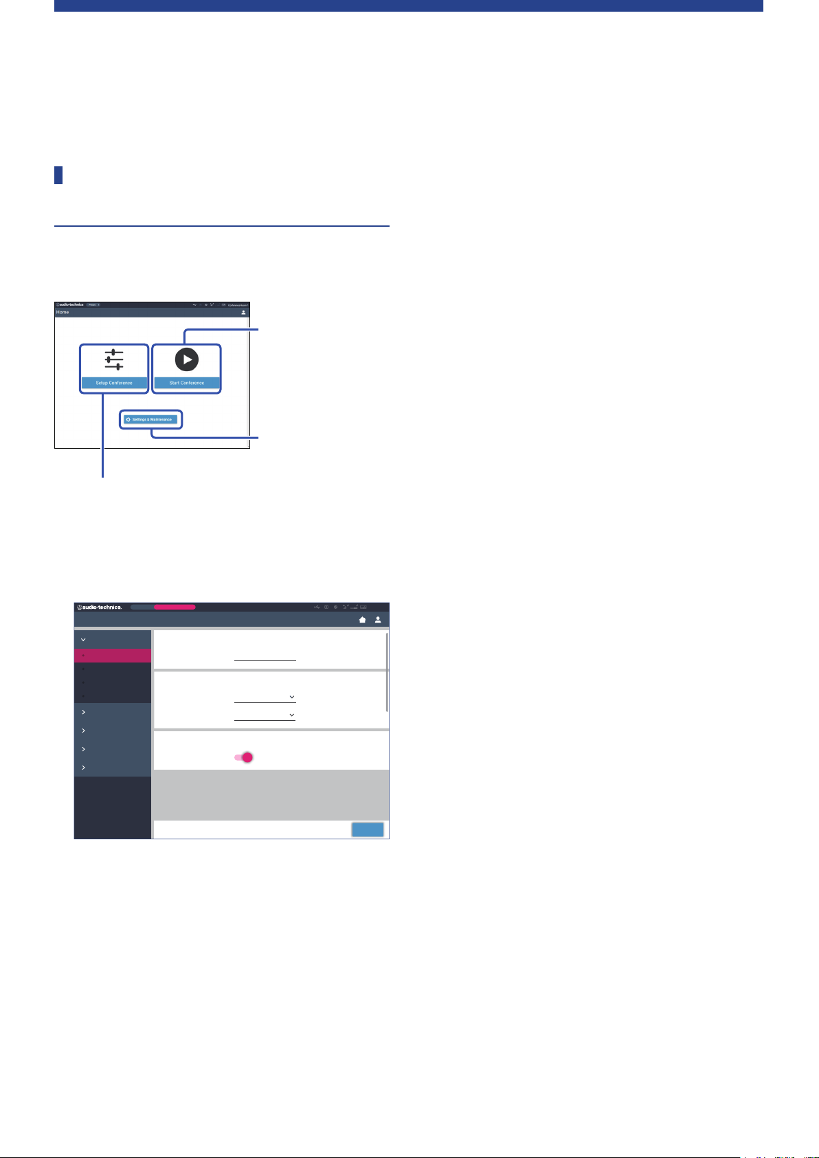
Overall structure of Web Remote
From the Home screen below, you can access the 3 main menus.
3. Operating and
controlling conferences
(Start Conference)
→
Select this to start a
conference using the
current settings.
1. Configuring detailed
settings of the system
(Settings & Maintenance)
2. Preparing for conferences (Setup Conference)
→
Select this to recall and adjust the preset settings as
necessary before starting a conference.
Configuring detailed settings of the system
1.
(Settings & Maintenance) (
Preset
Settings & Maintenance
System Settings
General
Network
User Access
Utilities
Install Settings
Presets
Logging
System Info
Under [Settings & Maintenance], the following 5 sub-menus are
available for configuring detailed settings of the entire system.
[System Settings] (
Allows you to set the unit name and a login password as well as
access authority setting, and configures network-related
settings.
You can also update the firmware from here.
[Install Settings] (
Allows you to select conference mode (
You can also configure advanced CU audio input/output
settings and recording settings.
Furthermore, you can configure DU detail settings, such as
speaker settings and LED color, for each DU and the
interpretation settings for each INT.
Monthly Sales Meeting
Device Name
Name
CU Link Settings
Link Port Setting
Primary/Extension Primary
CU Display / LED
Error Notification
page 37)
➤
page 42)
➤
page 36):
➤
ATUC-50
DU C/D
➤
page 45).
Apply
ATUC-50
[Presets] (
Allows you to preset settings configured from [Install Settings]
and recall the settings. You can also export the desired preset
setting and import it to another ATUC-50.
[Logging] (
Allows you to turn the logging function on/off and download a
log file.
[System Info] (
Displays the network setting information and firmware version.
Preparing for conferences (Setup Conference)
2.
page 55):
(
➤
Follow the 3 steps below to prepare for a conference.
[Recall Preset] (
Select the desired preset conference setting according to the
upcoming conference.
To handle many different types of conferences using 1 ATUC50 system, it is recommended to preset multiple types of
conference settings.
[Conference Settings] (
According to the upcoming conference, set the [Conference
Mode] (
configure the detailed settings.
[DU/IU Settings] (
For each DU/IU connected to the system, set the attendee name
and configure the audio settings and priority setting.
Operating and controlling conferences (Start
3.
Conference) (
Operate and control the conference by switching the screen
among the following 3 screens.
[Conference Manager] (
Displays an attendee (DU) list. The list shows information
including the attendee names, priority setting status and talk
request status. Furthermore, you can permit the attendees to
talk.
[Audio Control] (
Configure the primary output settings and perform audiorelated operations such as buzzer playback and conference
recording operations.
[Conference Settings] (
You can change detailed settings such as conference mode even
during the conference.
page 54)
➤
page 54)
➤
page 54)
➤
page 55)
➤
page 55)
➤
page 45), which defines the talk method, and then
➤
page 56)
➤
page 57):
➤
page 57)
➤
page 58)
➤
page 58)
➤
34
Page 35
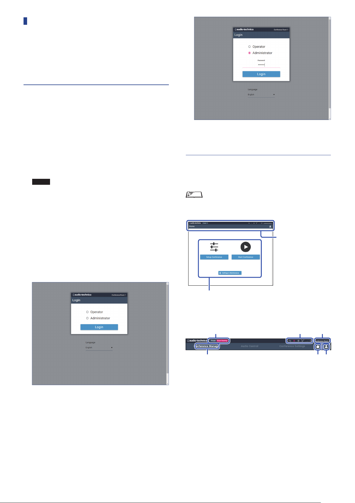
Starting up Web Remote and
①
② ③ ④
⑤ ⑥
preparing for operations
This chapter explains the Web Remote startup operation and the
header always displayed on the top of the screen.
Starting up and logging in to Web
Remote
Display the Web Remote login screen.
1
To log in to Web Remote from “Locate”:
(1) Follow steps 4 to 5 in “Setting up ‘Locate’” (
Web Remote starts up and the login screen appears.
To log in to Web Remote without using “Locate”:
NOTICE
Select [Operator] or [Administrator], then click
2
• Check that the CU is connected to the same network
as the control device. When using a control device
with a network terminal, you can also directly
connect the CU to the control device using an
Ethernet cable (
(1) From the CU Set Menu →
the IP address of the CU (
(2) Run the browser and type the IP address you checked in
step (1) in the address bar.
Web Remote starts up and the login screen appears.
page 32).
➤
System Info
page 10).
➤
IP Address
→
page 33).
➤
[Login].
, check
After successfully logging in to Web Remote, the Home screen
appears.
About Web Remote Home screen
• Depending on the [Operator] access authority setting,
[Settings & Maintenance] may not appear on the Home
screen.
Header always displayed on
the screen.
Access each screen (
page 36).
➤
To change the language, click [▼] next to the language display
to expand the drop-down list and select the desired language.
The [Operator] access authority can be set from [System
Settings] → [User Access] → [Operator Access Settings] (
38).
When a login password (
password on the password input screen.
page 38) is already set, enter the
➤
page
➤
About the display items on the header:
Displays the screen name (e.g. Home).
①
Displays the recalled preset conference name (
②
some changes have been applied to the recalled preset, the preset
characters will appear in white color.
Displays various indicators (
③
“▲” appears below the corresponding indicator. Placing the
cursor over the indicator will display the pop-up screen which
shows the details of the problem.
Displays the name of the unit such as ATUC-50CU which is
④
being controlled via Web Remote.
Home button: Click to return to the Home screen.
⑤
Logout button: Click to display the currently logged-in authority
⑥
and the logout menu.
page 9). If any problem occurs,
➤
➤
35
page 54). If
Page 36
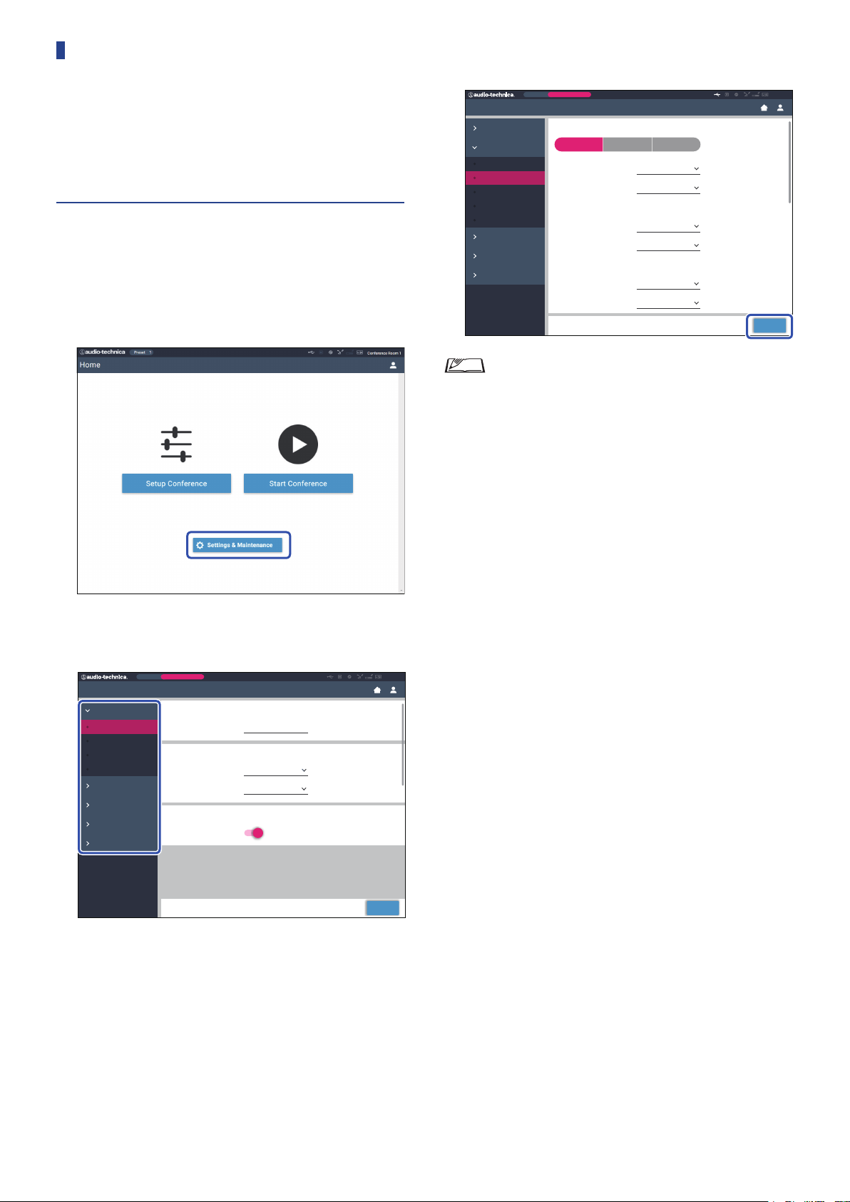
Configuring detailed system settings
([Settings & Maintenance])
From this menu, detailed system settings can be configured. Utilities
for troubleshooting and maintenance are also available.
How to operate the [Settings &
Maintenance] menu
On the Web Remote Home screen, click [Settings
1
& Maintenance].
Change the settings as necessary, then click
3
[Apply].
Preset
Settings & Maintenance
System Settings
Install Settings
CU Audio
Conference
DU/IU
Interpretation
Recorder
Presets
Logging
System Info
• The buttons displayed may vary depending on the screen.
• On screens where value changes are immediately applied,
such as on audio-related setting screens, the [Apply]
button may not appear.
Monthly Sales Meeting
Conference Mode
Free Talk Request Talk Full Remote
Number of Open Mics 10
Auto Mic OFF 10 sec
Override Mode No Override
Maximum in Queue 150
Mic ON Trigger No Connected DU
Mic ON Hold Time 2.5 sec
ATUC-50
Apply
From the 5 menu items on the left, click the item
2
you want to configure.
Preset
Settings & Maintenance
System Settings
General
Network
User Access
Utilities
Install Settings
Presets
Logging
System Info
Monthly Sales Meeting
Device Name
Name
CU Link Settings
Link Port Setting
Primary/Extension Primary
CU Display / LED
Error Notification
ATUC-50
DU C/D
ATUC-50
Apply
36
Page 37
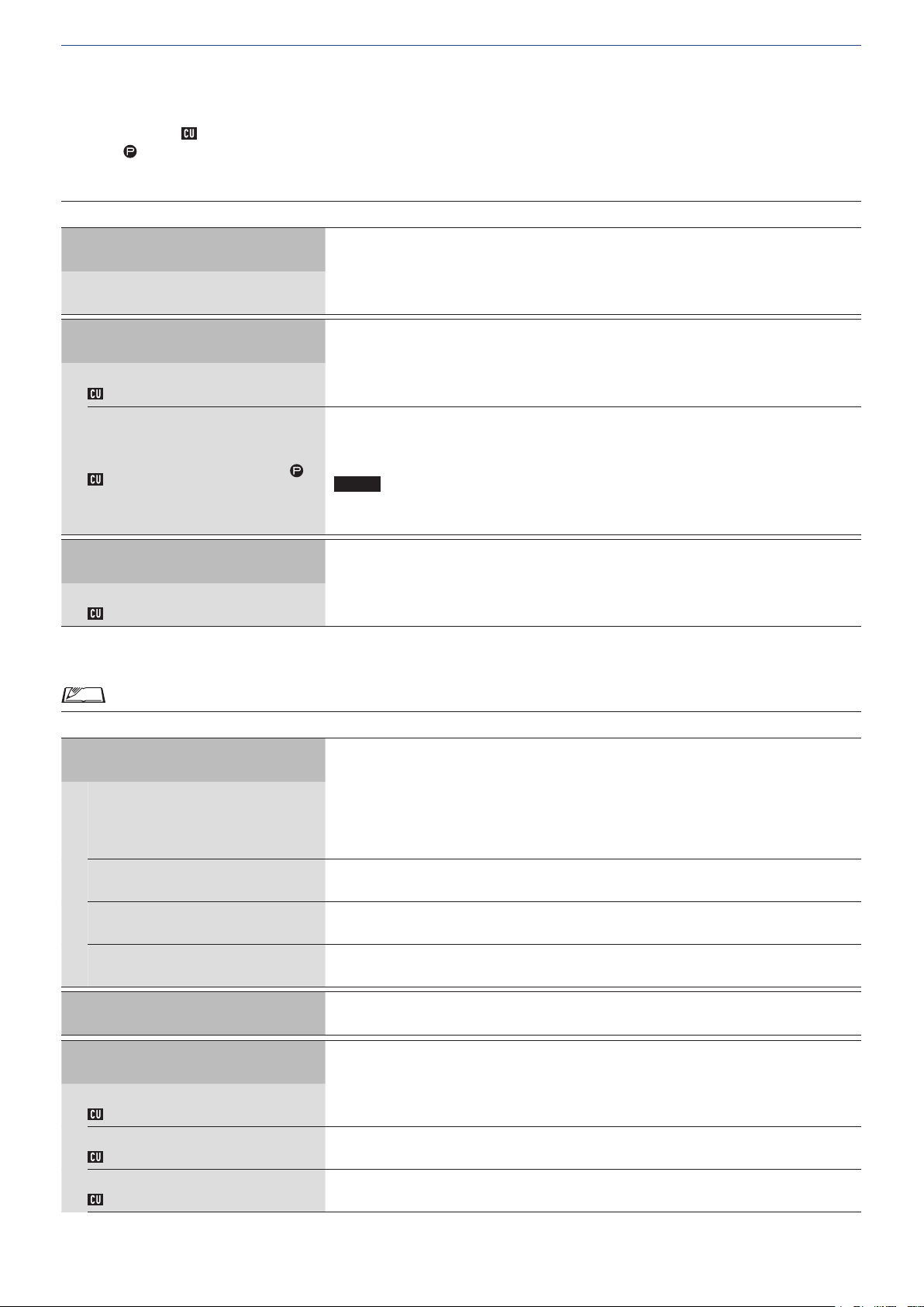
Menu item ① ([System Settings])
The setting values and default setting of each item which you can set from [System Settings] are as follows.
The item names with
Items with
are included in the preset settings.
General Settings ([General])
on the left are the names displayed on the CU display.
Item name
Device Name
Name
CU Link Settings
Link Port Setting
Link Port Set
Primary/Extension
CU Link Mode
CU Display/LED
Error Notification
CU Error Notice
Network Settings ([Network])
Description and setting values (default settings are shown in
Displays the name of the unit being controlled via Web Remote.
ATUC‑50CU
Switch the terminal setting between CU LINK A/B terminals and DU CHAIN C/D terminals.
, DU C/D
CU A/B
Set the dependency relationship of each CU (Primar y/Extension) when multiple CUs are cascadeconnected.
, Extension Pass Through, Extension Last Unit
Primary
NOTICE
• When using only one CU without a CU Link connection, be sure to set [CU Link
bold
)
Setting] to [Primary]. If [CU Link Setting] is set to [Extension], we do not assume
responsibility for any unexpected consequences that may occur.
Set whether to get error notices on the CU's display.
, Off
On
• After changing the network setting item(s), restart the CU to enable the setting values.
Item name
Description and setting values (default settings are shown in
IP Settings
Specify the IP address-acquiring method.
: IP address is assigned by a DHCP server or the like.
IP Config Mode
IP Address
Subnet Mask
Gateway Address
Allow Discovery
Auto
Static: Specify static IP address. This enables you to specify the IP address, subnet mask, and
gateway address.
Displays the IP address.
Does not display when [IP Config Mode] is set to [Auto].
Displays the subnet mask.
Does not display when [IP Config Mode] is set to [Auto].
Displays the gateway address.
Does not display when [IP Config Mode] is set to [Auto].
Enable/disable automatic detection from “Locate”.
, Off
On
IP Control Settings
Port Number
IP Ctrl Port No
Notification
IP Ctrl Ntfy
Audio Level Notification
Audio Level Ntfy
Displays the IP control port number.
00001-65535 (
Enable/disable notification from the device during IP control.
On,
Off
Enable/disable notification of the audio level from the device when IP control is enabled.
On,
Off
17300
)
bold
)
37
Page 38
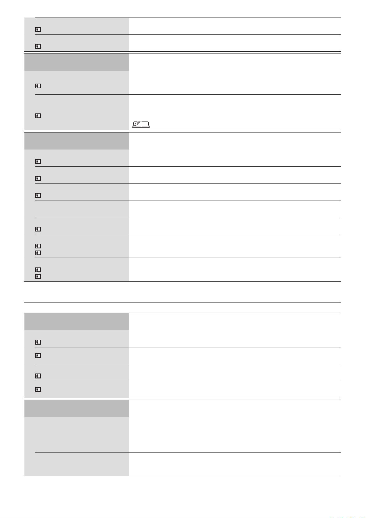
Multicast Address
M-cast Adrs
Multicast Port Number
M-cast Port No
Auto Mode Change When Network
Connection Lost
Enabled
Auto Mode Change
Hold time
Hold Time (Err)
NTP Settings
Specify multicast address.
0.0.0.0 - 255.255.255.255 (
Specify multicast port number.
00001-65535 (
Automatically switches the conference mode to [Free Talk] Mode when a network error occurs
while operating in [Full Remote] Mode.
, Off
On
Set the time interval until [Full Remote] Mode switches to [Free Talk] Mode after a network error
occurs.
, 30, 40 sec
20
17000
225.0.0.100
)
)
• During Web Remote control, the time interval may be longer by up to 15 seconds.
Enabled
NTP
Server Address
NTP Adrs
Port Number
NTP Port
Time Zone
Daylight Saving Time
DST
Start Date & Time
DST Start Date
DST Start Time
End Date & Time
DST End Date
DST End Time
Enable/disable NTP (Network Time Protocol).
On,
Specify the NTP sever address.
0.0.0.0 - 255.255.255.255 (
Specify the NTP port number.
00001-65535 (
Specify the time difference to UTC (Coordinated Universal Time).
UTC –12:00 to +14:00; in 0:30 minute increments (
Enable/disable the daylight saving time option.
On,
Set the start date and time for daylight saving time.
1/1 - 12/31 (
0:00 - 23:00; in 1 hour increments (
Set the end date and time for daylight saving time.
1/1 - 12/31 (
0:00 - 23:00 (
User Access Settings ([User Access])
Item name
Login Password
Description and setting values (default settings are shown in
Off
Off
123
3/27
10/30
2:00
)
Empty
)
)
00:00
)
)
2:00
)
)
)
bold
Administrator Password
Admin.Pwd.Login
Admin.Password
Operator Password
Opr.Pwd.Login
Opr.Password
Operator Access Settings
Home Page
Start Conference
Setup Conference
Settings & Maintenance
Enable/disable login password requirement for Administrator.
On,
Off
Set a login password for Administrator.
4 to 8 alphanumeric characters (
Enable/disable login password requirement for Operator.
On,
Off
Set a login password for Operator.
4 to 8 alphanumeric characters (
Configure settings of access authority granted to Operator.
Enable/disable function limitation for conference preparation ([Setup Conference]) and
conference operation and control ([Start Conference]).
, Limited
Full
Allow/restrict access to detailed settings ([Settings & Maintenance]). When this item is set to
[No], the [Settings & Maintenance] button will not appear on the Home screen.
Yes,
No
Empty
Empty
)
)
38
Page 39
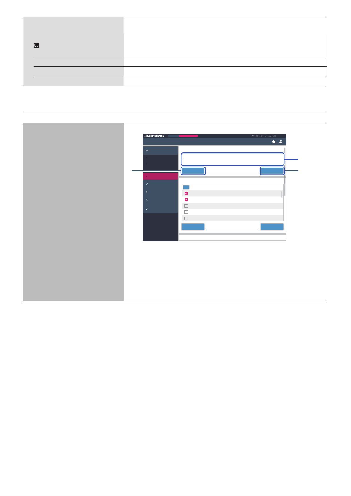
Settings & Maintenance
ATUC-50IU Firmware Update
①
③②
CU Display Menu
Enable/disable access authority for detailed setting of each item ([Settings & Maintenance] on Web
Set
Remote,
on the CU display).
Install Settings
Audio Setting, Recorder
Yes,
No
Setting
Presets
Logging
System Info Yes
Yes,
Yes,
No
No
, No
Utilities ([Utilities])
The following operations can be performed from [System Settings].
Item name
ATUC‑50CU Firmware Update
Description and operation procedure
Updates the CU firmware.
Preset
Monthly Sales Meeting
Settings & Maintenance
System Settings
General
Network
User Access
Utilities
Install Settings
Presets
Logging
System Info
Check the [Serial Number], [Device Name], and the current [Firmware Version] on the screen
①
ATUC-50CU Firmware Update
Serial Number
12345678
Browse Update
ATUC-50DU Firmware Update
Serial Number
All
16020431
16020432
16020433
16020434 1.0.4Lee Kim
16020435 1.0.4Miguel Silva
Browse Updatefirmware_DU_v104
Device Name
ATUC-50CU
firmware_CU_v104
Delegate Name
Ben Muller
AlexanderSminov
Raj Kumer
Firmware Version
1.0.3
Firmware Version
1.0.3
1.0.3
1.0.4
ATUC-50
to be sure that the displayed CU is the one you want to update.
Click [Browse] to display the file select screen and select the version upgrade file.
②
Click [Open] to start loading the file.
When the loading is complete, [Update] will be selectable. Click [Update].
③
After the confirmation message appears on the pop-up screen, click [Yes] to perform the update.
④
When the update is complete, [Completed. Device will automatically reboot momentarily.] will
appear and the CU will automatically restart in 3 seconds.
39
Page 40
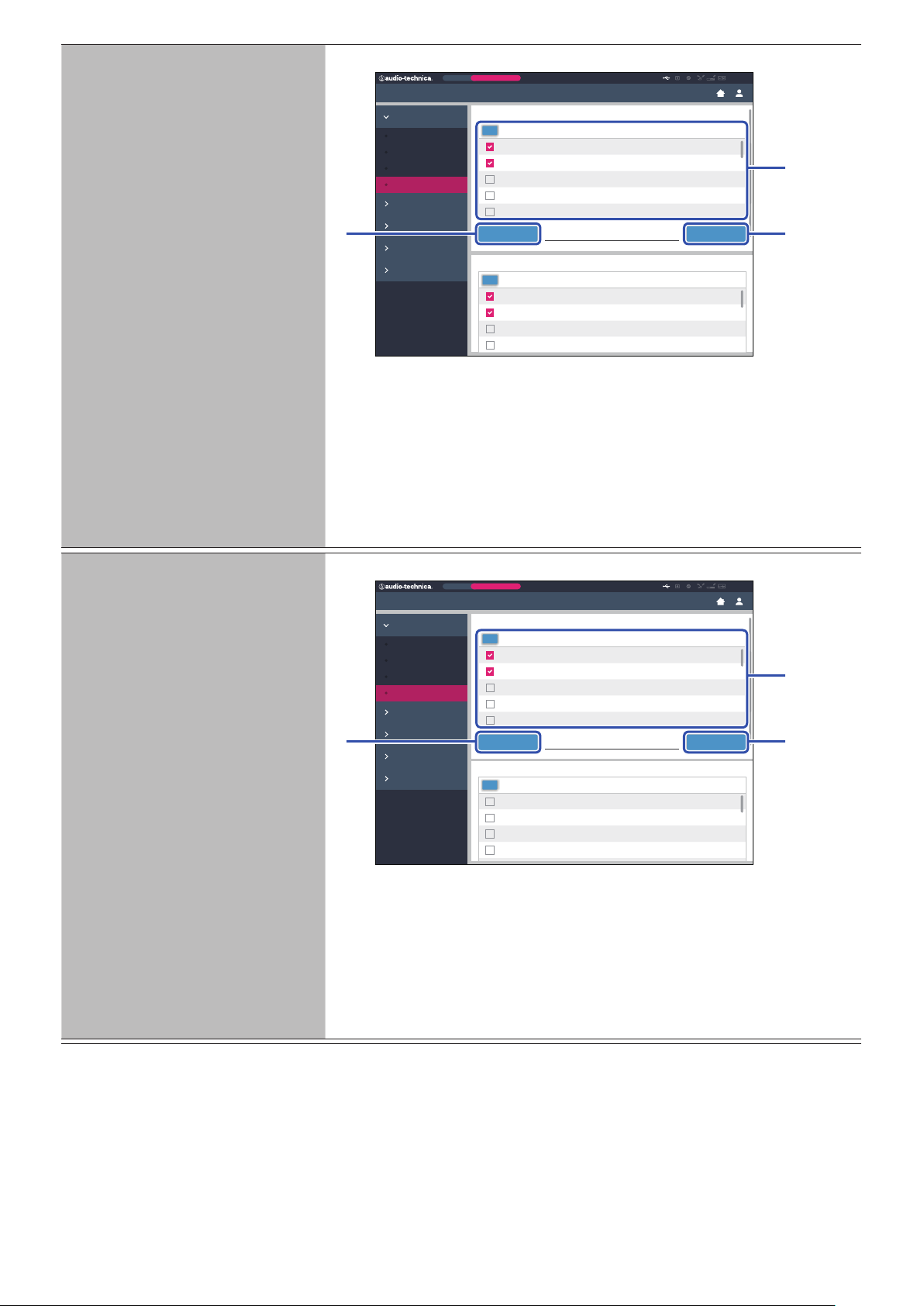
ATUC‑50DU Firmware Update
Browse Update
firmware_CU_v104
①
③②
Browse Updatefirmware_DU_v104
①
③②
Updates the DU firmware.
Preset
Monthly Sales Meeting
ATUC-50
Settings & Maintenance
System Settings
General
Network
User Access
Utilities
Install Settings
Presets
Logging
System Info
Click the checkbox next to the [Serial Number], [Delegate Name], and the current [Firmware
①
ATUC-50DU Firmware Update
Serial Number
All
16020431
16020432
16020433
16020434 1.0.4Lee Kim
16020435 1.0.4Miguel Silva
Browse Updatefirmware_DU_v104
Delegate Name
Ben Muller
AlexanderSminov
Raj Kumer
ATUC-50IU Firmware Update
Serial Number
All
01000001
01000002
01000003
01000004 1.0.3Maria Gonzalez
Delegate Name
Dong Wong
Cai Zhang
Jing Li
Firmware Version
1.0.3
1.0.3
1.0.4
Firmware Version
1.0.1
1.0.1
1.0.3
Version] of each DU you want to update.
When you want to select all DUs, click [All] on the upper left of the DU Firmware Update
section on the screen.
Click [Browse] to display the file select screen and select the version upgrade file.
②
Click [Open] to start loading the file.
When the loading is complete, [Update] will be selectable. Click [Update].
③
After the confirmation message appears on the pop-up screen, click [Yes] to perform the update.
④
When the update is complete, [Completed. Please turn power off.] will appear.
Turn off the power of the CU to restart it.
⑤
ATUC‑50IU Firmware Update
Update the IU firmware.
Preset
Monthly Sales Meeting
ATUC-50
Settings & Maintenance
System Settings
General
Network
User Access
Utilities
Install Settings
Presets
Logging
System Info
Confirm that [Serial Number], [Delegate Name], and the current [Firmware Version] appear on
①
ATUC-50IU Firmware Update
Serial Number
All
01000001
01000002
01000003
01000004 1.0.3Maria Gonzalez
01000005 1.0.3Santiago Hernandez
Browse Updatefirmware_IU_v103
Delegate Name
Dong Wong
Cai Zhang
Jing Li
ATUC-50INT Unit Firmware Update
Serial Number
All
02000001
02000002
02000003
02000004 1.0.0
Firmware Version
1.0.0
1.0.0
1.0.0
Firmware Version
1.0.1
1.0.1
1.0.3
the screen, and then select the check box on the left side of the IU units that you want to update.
If you want to update all of the IUs, click [All] at the top right.
Click [Browse] to display the file select screen and select the version upgrade file.
②
Click [Open] to start loading the file.
When the loading is complete, [Update] can be selected. Click [Update].
③
After the confirmation message appears on the pop-up screen, click [Yes] to perform the update.
④
When the update is complete, [Completed. Please turn power off.] appears.
Turn off the power of the CU, and then restart it.
⑤
40
Page 41

INT Unit Firmware Update
①
③②
Updates the INT firmware.
Click the checkbox next to the [Serial Number], [Delegate Name], and the current [Firmware
①
Version] of each INT you want to update.
When you want to select all INTs, click [All] on the upper left of the INT Unit Firmware Update
section on the screen.
Click [Browse] to display the file select screen and select the version upgrade file.
②
Click [Open] to start loading the file.
When the loading is complete, [Update] will be selectable. Click [Update].
③
After the confirmation message appears on the pop-up screen, click [Yes] to perform the update.
④
When the update is complete, [Completed. Please turn power off.] will appear.
Turn off the power of the CU to restart it.
⑤
Language Pack Installation
Reset All Settings to Default
Reset All Dflt.
Install the language pack.
Select the bank onto which you want to install the language pack.
①
Click [Browse] to display the file select screen and select the language file you want to install.
②
Click [Install] to install the language pack.
③
When the installation is complete, [Completed. You will be automatically logged out
momentarily.] will appear and you will be automatically logged out of Web Remote in 2
seconds.
To continue the operation, log in to Web Remote again.
Restores CU(s) and DU(s) and IU(s) and INT(s) to the default settings (this does not change the
firmware version).
When [Do you really want to reset all settings to default?] appears, click [Yes]. The
①
confirmation message will appear again.
Click [Ye s] to restore the default settings.
②
[Completed. Please turn power off.] will appear.
Turn off the power of the CU to restart it.
③
41
Page 42
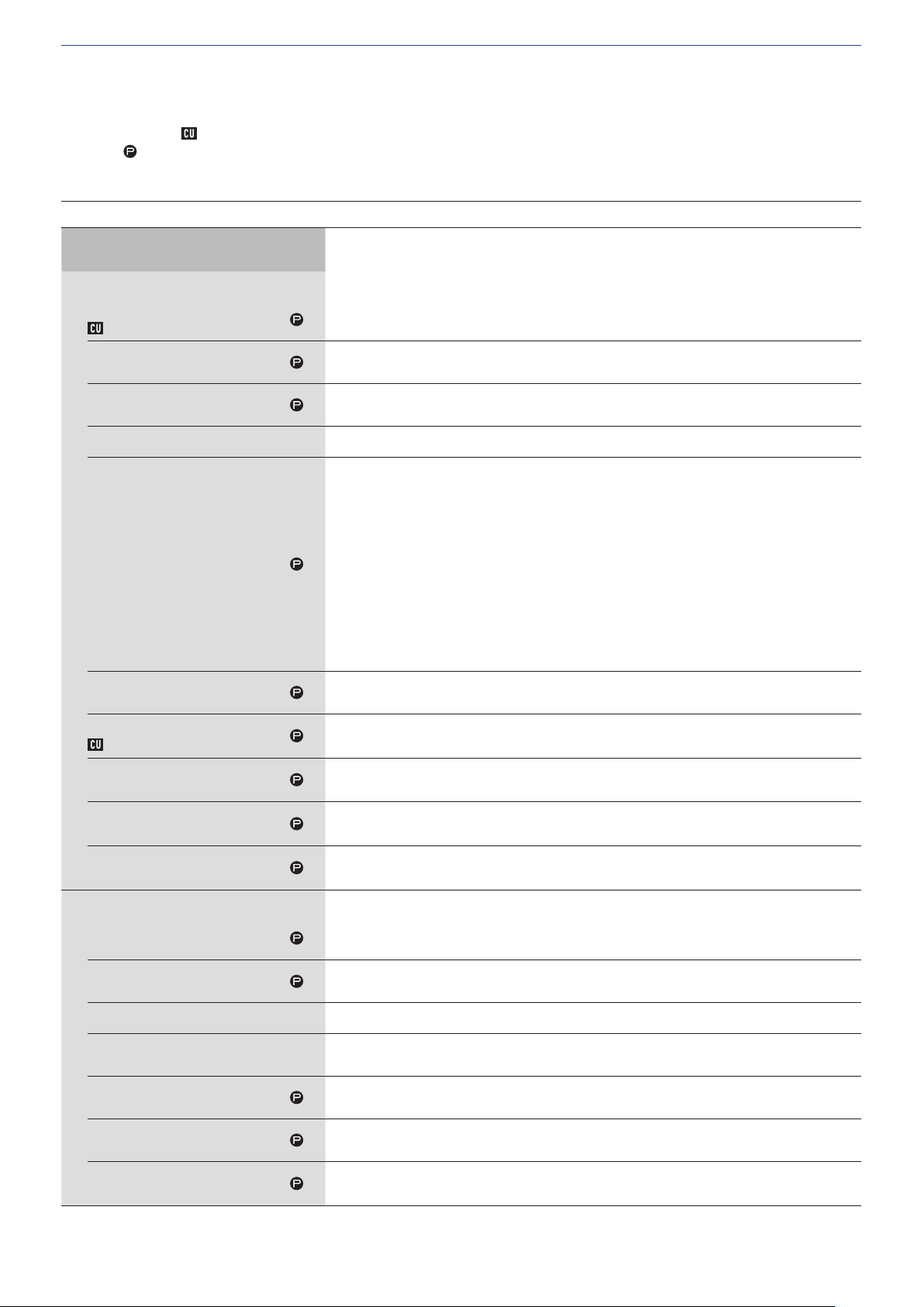
Menu item ② ([Install Settings])
The setting values and default setting of each item you can set from [Install Settings] are as follows.
The item names with
Items with
are included in the preset settings.
CU Audio Settings ([CU Audio])
on the left are the names displayed on the CU display.
Item name
Input Settings
Mic/Line 1-2
Type
Input Type
Input Gain
Level
Level Meter
EQ Library
Low Cut
Phantom
Phantom Power
Description and setting values (default settings are shown in
Set the type and level for the Mic/Line audio inputs 1 and 2. 1 and 2 can be configured
individually.
Set the input type.
, Line +4dBu, Line 0dBV
Mic
Set the input gain of the Mic inputs (only when [Type] is set to [Mic]).
–24 to +20dB (
Set the Mic/Line input level. The level can be set individually for each input type (Mic or Line).
–∞, –120 to +10dB (
Displays the input level with a level meter.
Select the EQ pattern for the Mic/Line inputs. The EQ pattern can be selected for each input type
(Mic or Line).
Flat
HH Dyn M: Dynamic Handheld Microphone for Male
HH Dyn F: Dynamic Handheld Microphone for Female
HH Cond M: Condenser Handheld Microphone for Male
HH Cond F: Condenser Handheld Microphone for Female
Lavalier M: Lavalier Microphone for Male
Lavalier F: Lavalier Microphone for Female
(IP Remote*)
* [IP Remote] appears when the equalizer is adjusted from [IP Control Settings]. [IP Remote]
cannot be selected from the drop-down list.
Enable/disable low frequency reduction for the Mic input.
,
Off
On
Enable/disable phantom power (+48V).
,
On
Off
0dB
)
0dB
)
bold
)
Mix to Floor
Mix to Language 1
(Only Mic/Line 1)
Mix to Language 2
(Only Mic/Line 2)
Aux
Type
Level
Level Meter
Low Cut
Mix to Floor
Mix to Language 1
Mix to Language 2
Set whether to mix the input sound to the floor channel.
, Off
On
Set whether to mix the voice being input with Language 1.
,
On
Off
Set whether to mix the voice being input with Language 2.
,
On
Off
Configure the external input settings such as audio type and level.
Set the nominal level of the external input.
, –10dBV, –20dBV
0dBV
Set the input level of the external input.
–∞, –120 to +10dB (
Display the input level with a level meter.
Enable/disable low frequency reduction for the external input.
On,
Off
Set whether to mix the external input sound to the floor channel.
, Off
On
Set whether to mix the voice being input with Language 1.
On,
Off
Set whether to mix the voice being input with Language 2.
On,
Off
0dB
)
42
Page 43
Return 1-2
Type
Level
Configure the level of the return input and the EQ pattern for the return input.
Set the nominal level of the return inputs.
, 0dBV
+4dBu
Set the input level of the return input.
–∞, –120 to +10dB (
0dB
)
Level Meter
Low Cut
Group settings
Gain share
Bypass
FBS
On
Feedback Suppression Settings
Frequency
Fixed
Displays the input level with a level meter.
Enable/disable low frequency reduction for the return input.
On,
Off
Do settings to bypass the gain share.
Group 0: On,
Group 1 to Group 3: On, Off
Configure the feedback suppressor (FBS) settings. Selecting the check box sets FBS of the
corresponding [Audio Group] to [On] and makes the setting button ( ) selectable. Click the
setting button ( ) to open the [Feedback Suppression Settings] screen and configure advanced
settings.
Group 0: On, Off
Group 1 to Group 3: On,
Detects feedback and displays the frequency with the notch filter applied. When [Static] is set to
[Off ], the frequency dynamically changes according to feedback detected.
*
* When [Static] is set to [On], the [Frequency] value is included in the preset setting as the
frequency of the static filter.
Lock the filter frequency by switching to the static filter.
On,
Off
Off
Off
Reset
Detection
Response
Group 0: Mix to Floor
Group 1: Mix to Language 1
Group 2: Mix to Language 2
Group 3: Mix to Language 3
Output Settings
Output 1-4
Source
PEQ
(Output 1 only)
PEQ Enabled
Unlock all locked frequencies.
Configure the detection sensitivity of feedback frequency.
Low,
Configure the detection speed of feedback frequency.
Slow,
Mix the voice of [Group 0] with the Floor.
On
Mix the voice of [Group 1] with Language 1.
On
Mix the voice of [Group 2] with Language 2.
On
Mix the voice of [Group 3] with Language 3.
On
Configure the output audio-related settings for each of OUTPUT terminals 1 to 4.
Set the audio source to output.
Floor, Group 0, Group 1, Group 2, Group 3, Language 1, Language 2, Language 3
(The default settings are as follows:
Output 1:
Configure the parametric equalizer (PEQ) settings. Ticking the checkbox sets PEQ of the
corresponding output to [On] and makes the setting button ( ) selectable. Click the setting
button ( ) to open the [PEQ Settings] screen and then configure settings for each of bands 1 to 8.
Switch the PEQ setting between on and off.
On,
Mid
, Off
, Off
, Off
, Off
Off
Fast
, High
Floor
, Output 2:
Group 1
, Output 3:
Group 2
, Output 4:
Group 3
)
43
Page 44
Frequency
(Band#1 ‑ Band#8)
Set the frequency for each of [Band#1] to [Band#8].
20Hz to 20kHz
(The default setting for each of [Band#1] to [Band#8] is as follows.
25, 63, 160, 400, 1000, 2500, 6300, 16000
Set the gain for each of [Band#1] to [Band#8].
–18dB to +10dB; adjustable in 0.5dB increments (
)
)
0dB
Gain
(Band#1 ‑ Band#8)
Q
(Band#1 ‑ Band#8)
Filter Type
(Band#1)
Filter Type
(Band#8)
Reset
Reset All
DYN
(Output 1 only)
Enabled
Gain Reduction
Comp Threshold
Ratio
Attack Time
Release Time
Limiter Threshold
Level
Max Volume
(Output 1only)
• For [Band#1], [Gain] is configurable only when [Filter Type] is set to [LSH] or
[PEQ].
• For [Band#8], [Gain] is configurable only when [Filter Type] is set to [HSH] or
[PEQ].
Set the Q value for each of [Band#1] to [Band#8].
• For [Band#1] and [Band#8], the Q value is configurable only when PEQ is enabled.
0.3 to 30 (10)
Set the filter type for [Band#1].
HPF, LSH,
Set the filter type for [Band#8].
LPF, HSH,
Restores specified band to the factory default settings.
Restores all bands to the factory default settings.
Configure the DYN (dynamics) settings. Ticking the checkbox sets DYN of Output 1 to [On] and
makes the setting button ( ) selectable. Click the setting button ( ) to open the [Dynamics
Settings] screen and then configure various settings as follows.
Enable/disable the dynamics settings.
On,
Displays audio compressed by the compressor in real time.
Configure the compressor threshold. The compressor functions only for audio signals exceeding
the specified value.
–60 to 0dB (
Set the compression ratio.
1.4:1,
Set the delay for the start of compression after audio signals exceed the threshold.
0, 0.25, 0.5, 1, 2, 4, 8, 16, 32, 100msec (
Set the delay for the end of compression after audio signals fall back within the threshold.
50, 100, 200, 400, 800, 1000, 2000msec (
Set the limiter threshold.
Audio signals exceeding the specified value will be cut out by the limiter.
–60 to 0dB (
Set the output level.
–∞, –120 to +10dB (
Set the maximum volume level.
–∞, –120 to
PEQ
PEQ
Off
–10
, 4:1, 6:1, 10:1, ∞:1
2:1
–10
+10dB
)
)
–40dB
)
1msec
400msec
)
)
44
Page 45
Conference Settings ([Conference])
Select the conference mode according to the conference operation and control method and configure detailed settings.
• The following setting items are also included in [Setup Conference] where you can configure the same settings.
• [Free Talk]
In this mode, attendees can talk when the (talk) button is pressed or when their DUs automatically detect their voices.
• [Request Talk]
In this mode, attendees request to talk by pressing the (talk) button on the DU and will be permitted to talk by the steering committee.
The steering committee can also reject the talk request.
To operate the conference in this mode, connect the CU to a control device such as a computer.
• [Full Remote]
In this mode, utterances are totally controlled via Web Remote. The DU (talk) button operations will be disabled.
To operate the conference in this mode, connect the CU to a control device such as a computer.
Item name
Conference Settings
Conference Mode
Number of Open Mics(*1)
NOM
Auto Mic OFF(*1)
Auto Mic Off
Override Mode (Free Talk
Mode)(*1)
Override Mode (Request Talk
Mode)(*1)
Override Mode (Full Remote
Mode)(*1)
Maximum in Queue(*1)
Max Queue
Mic ON Trigger / Mic ON Trigger
for Priority(*1)
MicON Trigger
Mic ON Hold Time(*1)
MicON Hold Time
Description and setting values (default settings are shown in
Select the conference mode and configure detailed settings
Select the conference mode.
Free Talk
Set the maximum number of the DUs (speakers) that can talk at the same time.
10
Set the time interval until the microphone automatically turns off after the speaker stops talking
(after a soundless state is detected).
5 to 60sec, Off; adjustable in 5-second increments (
Select the override method(*2) in [Free Talk] Mode.
No Override
Select the override method(*2) in [Request Talk] Mode.
FIFO
Select the override method(*2) in [Full Remote] Mode.
FIFO
Set the maximum number of DUs that can be in talk standby mode at the same time.
0 to 150 (
Set whether to manually turn on the microphone by pressing the
automatically turn on the microphone when a voice is detected, for all DUs.
When [Conference Mode] is set to [Request Talk] or [Full Remote], this item switches to [Mic ON
Trigger for Priority], which is the setting for priority D Us.
All Button
* The setting value displayed is depending on the setting values for each DU. When all DUs are set
Specify the time until the microphone automatically turns off on DUs where [Mic ON Trigger] is
set to [Voice ]. The microphone automatically turns off when the attendee keeps silent for the
specified time.
1.0 to 10.0 seconds; adjustable in 0.5-second increments (
, Request Talk, Full Remote
to 1
)
Off
, FIFO, LIFO
, LIFO
, LIFO
50 units
to [Button], [All Button] appears, and when all DUs are set to [Vo ic e], [All Voice] appears. When
some DUs are set to [Button] and others are set to [Voi ce ], [Individual] appears. [Individual]
cannot be performed as a function.
)
, All Voice, (Individual*)
)
bold
(talk) button or to
2.5 seconds
)
Priority Mode
Interrupt Option(*1)
Set the operation when the user of the priority DU (
(talk) button.
Set whether the priority DU user cuts short or temporarily mutes other DU users by pressing and
holding the
, Mute
Cut
(talk) button.
page 47) presses and holds the DU
➤
45
Page 46
SFX 1-3 Setting
Name
It is possible to replay any audio file, such as a buzzer or chime that has been saved to a USB device
(mass storage device).
A maximum of 3 audio files can be registered and assigned to the 3 buttons displayed on the [Audio
Control] screen. (
Specify names for buttons to which audio files are assigned.
(Up to 15 characters)
SFX1 to 3
Follow the procedure below to register audio files.
Copy audio files (up to 30 files) that you want to play to the root directory of a USB device
①
(mass storage device)
Connect the USB device (mass storage device) to CU
②
Select an audio file from the [Source] pulldown list
③
page 58).
➤
Playback(*1)
Source
WAV
Sampling frequency 48kHz
Bit rate 32-320kbps
MP3(*2)
Sampling frequency 48kHz
Maximum file size 2GB
Maximum number of files 30files
Data length 16bit, 24bit
*1 Supported file systems: FAT16/FAT32
*2 Supported format: MPEG-1 Audio Layer-3.
*1 About setting changes
Settings can be changed when all DUs are in the Talk OFF state.
*2 About the override setting
Specify which DU (speaker) is cut short and which DU’s request will be permitted if the number of DUs (speakers) who can talk at the same time has
already reached the specified maximum limit ([Number of Open Mics]) and more attendees press the
(talk) button.
FIFO (First-In First-Out):
Cuts short the speaker who was least recently permitted to talk and permits the person who has just pressed the (talk) button to talk.
LIFO (Last-In First-Out):
Cuts short the speaker who was most recently permitted to talk and permits the person who has just pressed the (talk) button to talk.
No Override:
(unselectable while in [Request Talk] Mode or [Full Remote] Mode)
The person who has just pressed the (talk) button will be in talk standby and will be permitted to talk when his/her turn comes.
DU/IU Settings ([DU/IU])
Item name
Global DU/IU Settings
Speaker Level
DU SP Output Lvl
Monitor CH Floor Lock
DU Floor Lock
Voice Detection Sensitivity
VoiceDetectSens
Auto relative to Mic2 Input
Auto to Mic2 In
DU Talk LED Color(*1)
Talk ON
Queuing
Non‑Priority IU GPIO 0
Description and setting values (default settings are shown in
Configure DU common settings. Basically apply the common setting of the DUs to the IUs, as well.
Set the speaker output level.
0 to 20 (10)
Switch the lock function for the monitor channel selection buttons.
On,
Off
Set the detection level when voices are detected in automatic mode.
–5, –4, –3, –2, –1, 0, 1, 2, 3, 4, 5 (0)
The voice detection level automatically adjusts to the level at which background noise is picked up
by the MIC2 input terminal.
On,
Off
Set the LED colors for DUs
Set the (talk) LED color when talking.
10 colors (
Set the (talk) LED color when waiting to talk.
10 colors (
Set the GPIO of the IUs with no priority to 0.
GPIO 0
)
Red
Green
, Self Mute
)
(talk). (Except for IUs)
bold
)
46
Page 47
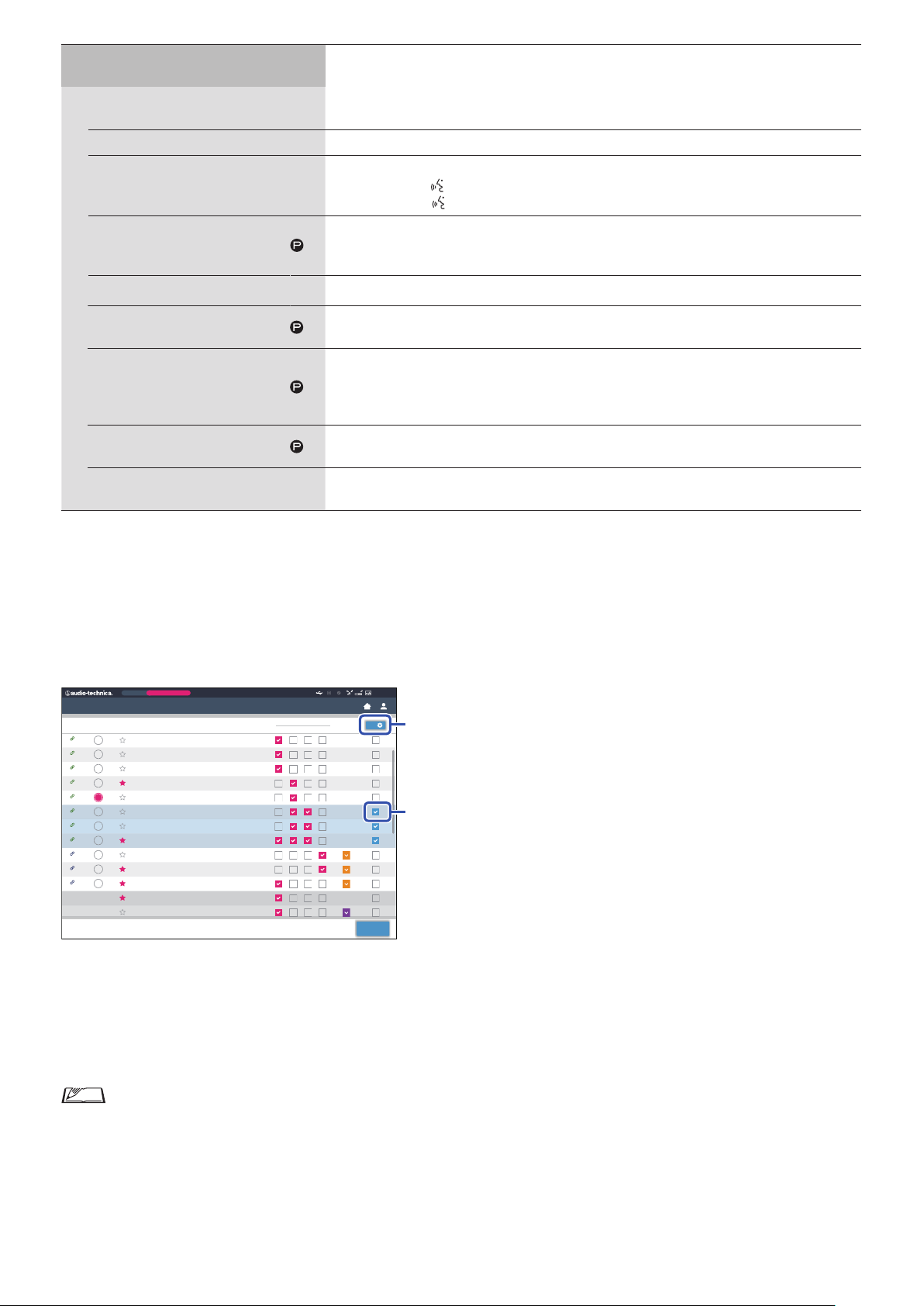
Individual DU/IU Settings
50 I U
50 I U
50 I U
50 DU
50 DU
50 DU
50 I U
50 I U
50 I U
50 I U
Preset
Monthly Sales Meeting
②
①
(Max. 300 units)
Connected DUs
Device icons
LED
Priority
Configure settings individually for each DU/IU.
Displays setting information of all DUs connected to the system. You can check and change
settings.
Icons that indicate the categories of the units connected to the system.
Check that the DU/IU LED lights up.
The rear LED and
the corresponding
(talk) LED on the DU as well as the ring LED on the ATUC-M blink while
(talk) icon on the screen is lit.
Enable/disable the DU/IU priority settings (*2). You can turn on priority for up to one unit fewer
than the maximum number of simultaneous speakers (➤page 45).
On,
Off
Serial#
Delegate Name
Displays the serial number.
Assign names (e.g. attendee names) to differentiate DU/IUs.
You can use up to 30 characters. (
8‑digit number
)
The output signals from each DU/IU can be categorized into 4 types (audio groups). One or more
Audio Group
Color
Operations for the DU(*3)
audio groups can be selected as output destination(s), and furthermore, the output terminal on the
CU can be specified for each group (➤page 43).
Group 0
, Group 1, Group 2, Group 3
Select a color for the rear LED from the drop-down list.
10 colors (
Red
)
Select 1 or more DU/IUs from the list and perform the following operations.
Edit Detail Settings, Copy, Select all, Deselect all, Delete
*1: About setting changes
Settings can be changed when all DU/IUs are in the Talk OFF state.
*2: About the priority setting
Priority DU/IU(s) are given authorization to do the following:
• Talk anytime
• Cut short or temporarily mute all other attendees simultaneously
It is assumed that the priority setting is enabled on DU/IUs that are used by people in charge of the proceedings of a conference, such as a chairman
or company directors who are permitted to talk anytime.
*3: DU/IU operations
Color
ATUC-50
0
Back
Connected DU/IUs
LED Priority
93
94
95
96
97
98
50 I U
99
100
101
102
103
Disconnected
Disconnected
Serial#
02001293
02001294
02001295
02001296
02001297
02001298
02001299
02001300
01001501
01001502
01001503
00315212
00315213
Delegate Name
Dong Wang
Cai Zhang
Jing Li
Kohei Matsuda
Santiago Hernandez
Linh Thi Nguyen
Lucia Garcia
Emma Smith
Ben Muller
Alexander Smirnov
Raj Kumar
Lee Kim
Miguel Silva
Audio Group
0 1 332
Click ① of the DU/IU(s) for which you want to adjust the settings.
1
A check mark will be inserted in the checkbox.
You can also select multiple DU/IUs and simultaneously change settings of the selected DU/IUs.
Click ② to display the drop‑down list and proceed to the following operations.
2
• The number displayed on ② is the number of selected DU/IUs.
Edit Detail Settings:
Simultaneously configure detailed settings for the selected DU/IUs (refer to the [DU Detail Settings] table below).
When multiple DU/IUs are selected, setting items for which the current values differ among the DU/IUs will be grayed out.
• Items which remain grayed out: Setting values of each DU/IU are retained.
• Grayed out items which become selectable after operation: Setting values of all selected DU/IUs will be changed to the displayed values.
47
Page 48
Copy:
Copies settings of the selected DU/IU and pastes to other DU/IUs.
Select 1 DU from which you want to copy settings.
①
Select [Copy] from the drop-down list.
②
All checkboxes, icons and the like except DU/IU select checkboxes will be unselectable.
Select the DU/IU(s) to which you want to paste the settings.
③
Press the [Paste] button.
④
Delete:
Deletes the selected DU/IU(s) from the list. Only DU/IU(s) in a disconnected state can be deleted.
Select all:
Selects all DU/IUs.
Deselect all:
Deselects all DU/IUs.
• Depending on the DU/IU selection state, some items above may not appear.
DU/IU Detail Settings ([DU/IU Detail Settings])
Item name
Microphone
Level Meter
Input Gain
AGC
EQ Library
Mic ON Trigger
Phantom Power
Speaker
Description and setting values (default settings are shown in
Configure microphone-related settings.
Displays the level with a level meter.
Set the microphone input gain.
–20dB to +20dB (
Enable/disable AGC (Automatic Gain Control).
On,
Off
NOTICE
• When operating the system with [AGC] set to [On], set the [Mode When Talk ON]
0dB
)
bold
)
setting under [Speaker] to [Attenuation] or [Off ].
Set the EQ pattern for the microphone input.
, Neutral Male, Neutral Female, Clear Male, Clear Female, Warm Male, Warm Female, AT ES
Flat
Series, AT UniPoint, (IP Remote*)
* [IP Remote] appears when the equalizer is adjusted from [IP Control Settings]. [IP Remote]
cannot be selected from the drop-down list.
Set whether to manually turn on the microphone by pressing the (talk) button or to
automatically turn on the microphone when a voice is detected.
, Vo ic e
Button
Enable/disable the phantom power supply to the microphone.
, Off
On
Enabled
Mode When Talk ON
Audio Group
Assign
Rear LED Color
(This is a setting item only for DUs.)
Talk ON / Queuing
Enable/disable the DU/IU speaker.
, Off
On
The attendee switches speaker mode while talking. When [Attenuation] is selected, the ducking
feature lowers the volume level by –20dB (this item appears only when the speaker is enabled).
On,
Attenuation
The CU categorizes the audio signals transmitted from the DU/IUs and then outputs the signals to
the specified channels.
Up to 4 channels can be specified for each DU. Multiple groups can be selected and output channels
can be selected for each group (
Group 0
Select a color for the rear LED from the drop-down list.
10 colors (
, Group 1, Group 2, Group 3
Red
, Off
page 43).
➤
)
48
Page 49

Talk OFF
Set how Talk OFF is lit.
, Dim
Off
Priority
Enabled
Can Cut/Mute
Can be Cut/Muted
GPI Pin Settings
(This is a setting item only for IUs.)
GPI 0 ‑ 7
Configure the priority (
Enable/disable the priority setting. The maximum number of DUs that can be designated as
priority DU is 1 unit less than the maximum number of DUs (speakers) that can talk at the same
time (
page 45).
➤
On,
Off
page 47) settings.
➤
Set whether the priority DU user can temporarily cut short/mute other DUs.
, Off
On
Set whether the priority DU are temporarily cut short/muted by other DUs.
On,
Off
Set the function to assign GPI ports 0 to pin 7.
(x is any port number 0 to 7): use as a general purpose input pin
GPI x
Self-Mute: The unit mutes the voice from its own microphone (self-mutes)
Permit Next: Permits the DU on the top of the list to talk
Master Volume Up: Turns up the volume for the master level
Master Volume Down: Turns down the volume for the master level
Recall Preset 1: Recalls preset 1
Recall Preset 2: Recalls preset 2
Recall Preset 3: Recalls preset 3
Recall Preset 4: Recalls preset 4
Recall Preset 5: Recalls preset 5
Recall Preset 6: Recalls preset 6
Recall Preset 7: Recalls preset 7
Recall Preset 8: Recalls preset 8
REC Start: Starts recording
REC Stop: Stops recording
SFX 1: Plays and stops SFX 1
SFX 2: Plays and stops SFX 2
SFX 3: Plays and stops SFX 3
49
Page 50

GPO Pin Settings
(This is a setting item only for IUs.)
GPI 0 ‑ 7
Set the function to assign GPO port 0 to port 7.
(x is any port number 0 to 7): use as a general purpose output pin
GPO x
Self-Mute Indicator: Indicates when self-muted
Lit: Self-muted
Cut/Mute Indicator: Indicates when a mic is disconnected or muted
Lit: Muted Blinking: Cut
Preset 1 Indicator: Indicates when preset 1 is called
Lit: Call done Blinking: Selecting
Preset 2 Indicator: Indicates when preset 2 is called
Lit: Call done Blinking: Selecting
Preset 3 Indicator: Indicates when preset 3 is called
Lit: Call done Blinking: Selecting
Preset 4 Indicator: Indicates when preset 4 is called
Lit: Call done Blinking: Selecting
Preset 5 Indicator: Indicates when preset 5 is called
Lit: Call done Blinking: Selecting
Preset 6 Indicator: Indicates when preset 6 is called
Lit: Call done Blinking: Selecting
Preset 7 Indicator: Indicates when preset 7 is called
Lit: Call done Blinking: Selecting
Preset 8 Indicator: Indicates when preset 8 is called
Lit: Call done Blinking: Selecting
REC Indicator: Indicates when recording
Blinking: Recording
SFX 1 Indicator: Indicates when SFX 1 is playing back
Blinks: Playing back SFX 1
SFX 2 Indicator: Indicates when SFX 2 is playing back
Blinks: Playing back SFX 2
SFX 3 Indicator: Indicates when SFX 3 is playing back
Blinks: Playing back SFX 3
50
Page 51

Interpretation Settings ([Interpretation Settings])
Item name
Interpretation Settings
Interpretation Mode
Easy Mode
Language Name
Audio Group 1
Audio Group 2
Audio Group 3
Description and setting values (default settings are shown in
Set the interpretation mode.
Automatically toggles the voice on the floor with the voice of the interpreter.
When [On] is set, for example, the voice on the floor is automatically output to language group
1 by putting INTs that are outputting an interpreter’s voice to language group 1 on All Talk
OFF.
On,
Set the Language Name for Audio Group 1.
(Up to 15 characters)
Set the Language Name for Audio Group 2.
(Up to 15 characters)
Set the Language Name for Audio Group 3.
(Up to 15 characters)
NOTICE
3 Languages
• Displayed only when “3 Languages” is selected in Interpretation Mode.
)
Interlock Mode
INT Unit Settings
(Max. 6 units)
Connected INT Units
LED
Serial#
Interpretation Languages
Operations of the INT Unit Settings (*1)
Set Interlock Mode for interpretation units with the same settings.
Configure settings individually for each INT.
Display setting information of all INTs connected to the system. You can check and change
settings.
Check that the INT LED lights up.
The rear LED on the INT, ring LED on the ATUC-M, and (talk) LED blink while the
corresponding icon on the screen is lit.
Displays the serial number.
Select the pattern for the languages to be interpreted. The language name selected from the
selection list appears in [Language Name].
Additionally, patterns and the number of languages depend on the setting values of
[Interpretation Mode].
2: Language 2 → 1: Language 1
2: Language 2 ↔ 3: Language 3, 1: Language 1 → 2: Language 2,
2: Language 2 → 1: Language 1, 1: Language 1 → 3: Language 3,
3: Language 3 → 1: Language 1, 2: Language 2 → 3: Language 3,
3: Language 3 → 2: Language 2
Interlock, Combine
, 1: Language 1 → 2: Language 2,
, 1: Language 1 ↔ 3: Language 3,
51
Page 52
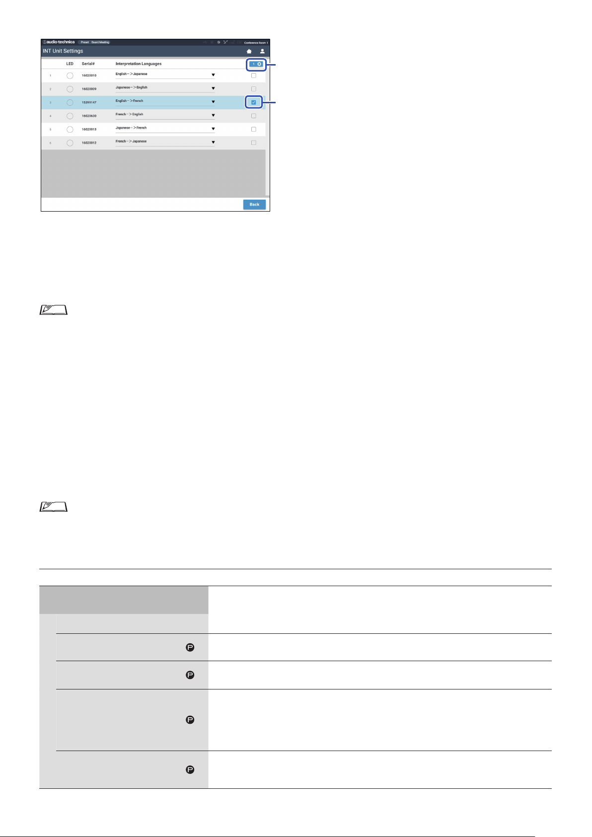
*1: About Operations of the INT Unit Settings
②
①
Click ① the INT(s) for which you want to change the settings.
1
A check mark appears in the checkbox.
You can also select multiple INTs and simultaneously change settings of the selected INTs.
Click ② to display the drop‑down list and proceed to the following operations.
2
• The number shown on ② indicates the number of the currently selected INTs.
Edit Detail Settings:
Configure the detailed settings of the INT(s) you selected (refer to the table below on detailed settings for INTs [INT Unit Detail
Settings]). When multiple INTs are selected, setting items for which the current values differ among the INTs are grayed out.
• If items remain grayed out: Setting values of each INT are retained.
• If grayed out items become selectable after operation: Setting values of all selected INTs will be changed to the displayed values.
Select all:
Selects all INTs.
Deselect all:
Deselects all INTs.
Delete:
Deletes the selected INT(s) from the list. Only INT(s) that have been disconnected can be deleted.
• Depending on the INT selection state, some items above may not appear.
• There is no function to copy the settings of an INT to other INTs.
INT Unit Detail Settings ([INT Unit Detail Settings])
Item name
Microphone
Level Meter
Description and setting values (default settings are shown in
Configure microphone-related settings for the INT(s).
Displays the level with a level meter.
)
Input Gain
AGC
EQ Library
Phantom Power
Set the microphone input gain.
–20 to +20dB (
Enable/disable AGC (Automatic Gain Control).
On,
Set an EQ pattern to be applied to the microphone input.
Flat, Neutral Male, Neutral Female, Clear Male, Clear Female, Warm Male, Warm Female, AT ES
Series, AT UniPoint, (IP Remote*)
* [IP Remote] appears when the equalizer is adjusted from [IP Control Settings]. [IP Remote]
cannot be selected from the drop-down list.
Enable/disable the phantom power supply to the microphone.
, Off
)
52
Page 53
Recording Settings ([Recorder])
NOTICE
• Recording settings can be configured only when recording stops.
Item name
USB Recorder Settings
Record File Format
Rec Format
Recording Quality
Number of Recording Channels
(WAV)
No.of Rec CH
Number of Recording Channels
(MP3)
No.of Rec CH
Recording Source
Track1, Track2, Track3, Track4
Rec Source CH1-CH4
Auto Track
Rec Filename Prefix
Filename Prefix
Description and setting values (default settings are shown in
Select the conference recording format.
, MP3
WAV
Set the bit rates for recording speech in MP3 format.
64, 128, 192, 256,
Set the number of recording audio channels when the recording format is WAV.
1 to
4
Set the number of recording audio channels when the recording format is MP3.
1 to
2
Set the recording source for each channel.
, Group 0, Group 1, Group 2, Group 3 , Language 1, Language 2, Language 3, Remote Lang. 1,
Floor
Remote Lang. 2, Mic/Line 1, Mic/Line 2, Mic/Line 1&2 Mix
Split audio files by the specified time while recording or disable this function.
, 15 min, 30 min, 1 hour, 2 hours
Off
Specify prefix for recorded audio files.
Up to 30 characters can be used. (Some characters cannot be used (
setting is
atuc‑50
320
.)
kbps
)
bold
page 23). The default
➤
53
Page 54
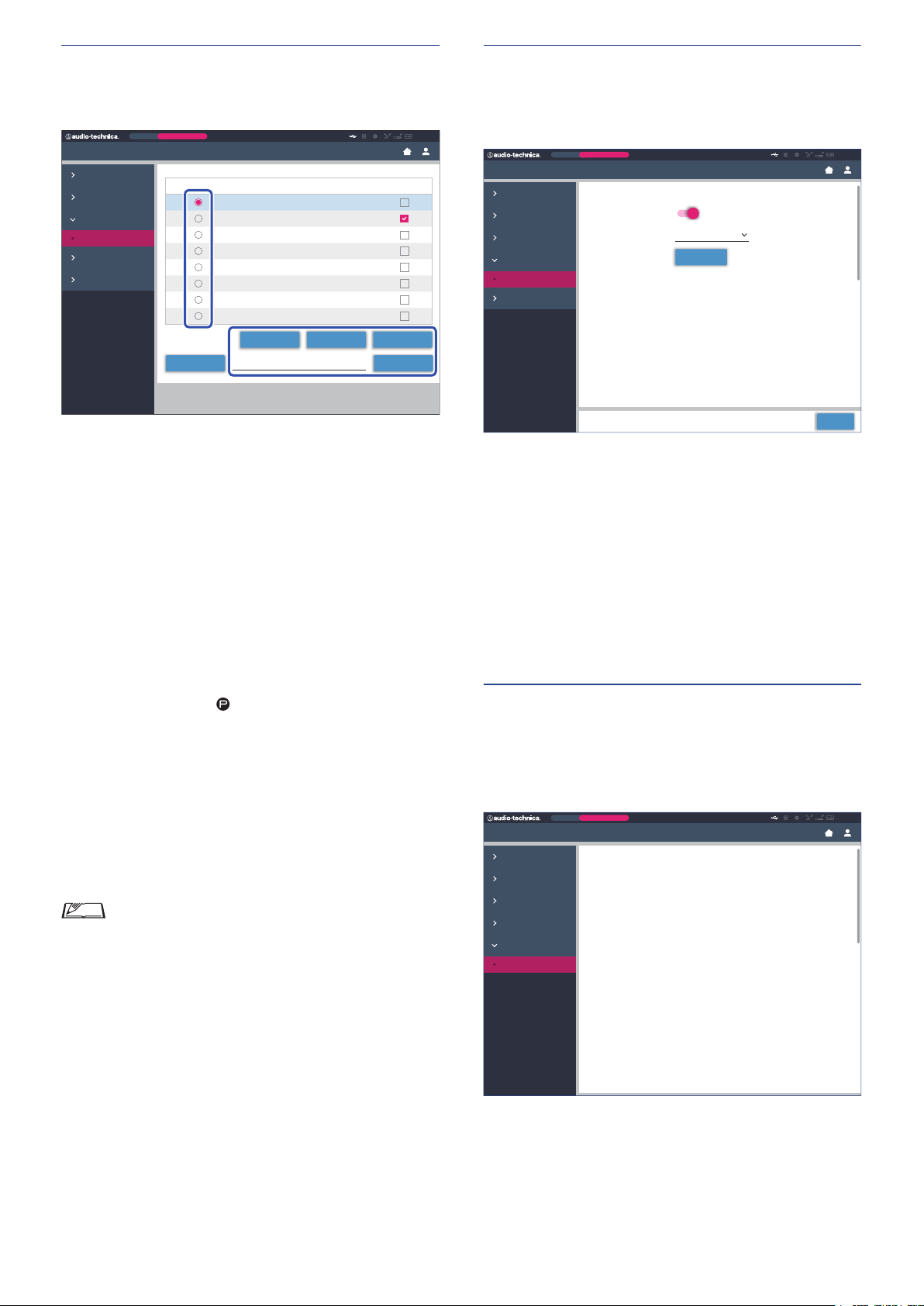
Accessing your presets ([Presets])
Extension 2:
Log management ([Logging])
Recall, save, import/export presets.
Preset
Monthly Sales Meeting
Settings & Maintenance
System Settings
Install Settings
Presets
Presets
Logging
System Info
Click ○ on the right side of the preset number
1
Presets
Preset Name
1
Board Meeting
2
Monthly Sales Meeting
3
Preset 3
4
Preset 4
5
Preset 5
6
Preset 6
7
Preset 7
8
Preset 8
Browse Importfirmware_DU_v104
you want to select.
will light red and the field of the selected preset will be
○
highlighted in light blue.
Click the operation you want to perform.
2
The selected operation will be executed.
Recall (
Sets the selected preset as the current setting.
Recall Presets
):
Boot Up Preset
ExportSaveRecall
ATUC-50
Configure the system log settings. You can also download the log
file.
Preset
Monthly Sales Meeting
Settings & Maintenance
System Settings
Install Settings
Presets
Logging
Logging
System Info
Enabled (
Logging
Enabled
Output Destination USB
Log File
Logging
Download
Apply
):
Set whether to save the system log. (On, Off )
Output Destination (
Destination
):
Set whether to export the log file to a USB device (mass storage
device). (
Internal
, USB)
Log File:
Select the download destination and download the log file to the
specified destination.
ATUC-50
Save Presets
Save (
):
Saves the current setting to the selected preset number.
The setting items with “
” in the table are included in the
preset.
Export (
Export Presets
):
Exports the preset data to an external device. From the pop-up
window, select the folder where you want to export the data.
Import (
Import Presets
):
Imports the preset data that was exported to an external device.
From the pop-up window, select the preset data file you want to
import.
• To edit the preset name, click the name. You can use up
to 30 characters.
• If you want to do settings to call a specific preset while
the system is starting, select that preset’s number.
Displaying the system information
([System Info])
Display the system information such as the firmware version,
various network setting statuses, and unit serial numbers.
Preset
Monthly Sales Meeting
Settings & Maintenance
System Settings
Install Settings
Presets
Logging
System Info
System Info
System Info
General
Device Name: ATUC-50
Serial Number: 12345678
Firmware Version: 09.02.00
Network
IP Config Mode: Auto
IP Addresss: 255.255.255.255
Subnet Mask: 255.255.255.255
Gatewary Address: 10.0.0.1
Allow Discovery: On
IP Control Port Number: 17300
Notification: On
Audio Level Notification: On
Multicast Address: 255.255.255.255
Multicast Port Number: 65535
NTP: On
NTP Server Address: 255.255.255.255
NTP Port Number: 65535
Time Zone: UTC-9:00
CU Link Status
CU Link Status: On
CU Link Mode: Primary
Number of Extension CU: 2
Extension 1:
Device Name: ATUC-50
Serial Number: 12345678
Firmware Version: 09.02.00
ATUC-50
54
Page 55

Preparing for conferences ([Setup
Conference])
To handle many different types of conferences using an ATUC-50
system, it is recommended to preset multiple types of conference
settings. Basic conference preparation can be carried out simply by
recalling the preset that best suits an upcoming conference.
Up to 8 conference settings can be preset.
You can also change settings saved on the recalled preset to suit the
upcoming conference.
Prepare for the upcoming conference in 3 steps by utilizing the
preset function.
Recalling the preset ([Recall Preset])
1
Recalls the preset and then displays the [Conference Settings]
screen.
The [Recall Preset] screen will appear if you click [Setup
Conference] on the Home screen (
For starting a conference using the most recently used conference
setting (Current Settings) or one of the preset settings, follow the
procedure below to display the [Conference Manager] screen.
On the [Recall Preset] screen, select [Current
1
page 35).
➤
Settings] or your desired preset and then click
[Next].
Changing the conference settings
2
([Conference Settings])
Change the settings as necessary and then click
1
[Next].
Saves the settings and displays the [DU/IU Settings] screen.
• To configure settings based on the current setting, select
[Current Settings].
55
Page 56
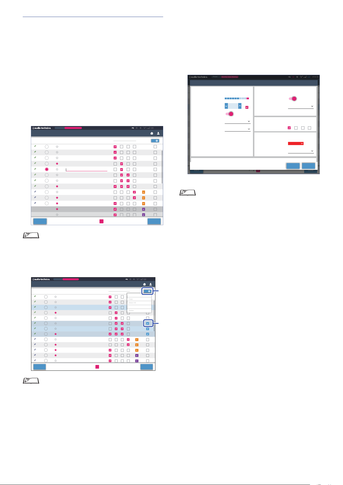
Adjusting the DU/IU settings ([DU/IU
Copy
Select All
Delete
②
①
Discussion Unit 12
Priority
3
Settings], [DU/IU Detail Settings])
Configure DU/IU settings ([DU/IU Settings]) and DU/IU detail
settings ([DU/IU Detail Settings]).
Change the settings as necessary.
1
To configure detail settings:
Proceed to step 2.
To finish settings without configuring detail
settings:
Click [Next], then click [Done].
Preset
Priority
Priority
Preset
Monthly Sales Meeting
Delegate Name
Dong Wang
Cai Zhang
Jing Li
Kohei Matsuda
Santiag
Linh Thi Nguyen
Lucia Garcia
Emma Smith
Ben Muller
Alexander Smirnov
Raj Kumar
Lee Kim
Miguel Silva
Monthly Sales Meeting
Delegate Name
Dong Wang
Cai Zhang
Jing Li
Kohei Matsuda
Santiago Hernandez
Linh Thi Nguyen
Lucia Garcia
Emma Smith
Ben Muller
Alexander Smirnov
Raj Kumar
Lee Kim
Miguel Silva
1 2 3
1 2 3
page 46).
➤
1 2 3
Audio Group
0
Audio Group
0 1 342
1 3
2
Edit Detail Settings
Deselect All
Color
Color
Done
0
0
Done
ATUC-50
0
DU/IU Settings
LED
93
50 I U
94
50 I U
95
50 I U
96
50 I U
97
50 I U
98
50 I U
99
50 I U
100
50 I U
101
50 DU
102
50 DU
103
50 DU
Disconnected
Disconnected
Back
• For details on each setting item, refer to the [DU/IU
Settings] item table (
Click ① of the DU/IU(s) for which you want to
2
change the settings, to enter a ✔ mark.
DU/IU Settings
LED
93
50 I U
94
50 I U
95
50 I U
96
50 I U
97
50 I U
98
50 I U
99
50 I U
100
50 I U
101
50 DU
102
50 DU
103
50 DU
104
50 DU
105
50 DU
Back
ATUC-50
From the drop‑down list ②, click [Edit Detail
3
Settings].
Displays the [DU/IU Detail Settings] screen and enables you to
configure DU/IU detail settings.
Configure DU/IU detail settings and click [Apply]
4
to apply the changes.
Preset
DU Setting
DU/IU Detail Settings
LEDTalk
Microphone
93
Level Meter
94
Input Gain
95
96
AGC
97
EQ Library
98
Mic ON Trigger
99
100
101
102
103
104
105
Back
Returns to the [DU/IU Settings] screen.
• For details on each setting item, refer to the [DU/IU
Detail Settings] item table (
• When multiple DU/IUs are selected, setting items for
which the current values differ among the DU/IUs will
be grayed out. These setting items cannot be adjusted.
• The [Phantom Power] setting for DU/IUs can be
configured from [Settings & Maintenance] → [Install
Settings] → [DU/IU] → [Individual DU/IU Settings] →
[Connected DU/IUs] → [Edit Detail Settings] → [DU/IU
Detail Settings] (
Click [Done] on the bottom right of the screen.
5
The [Conference Manager] screen under [Start Conference]
appears (
the conference.
Monthly Sales Meeting
Priority Delegate Name
0123456789012345678901234567890
-30 0 PK12-12-50 6-6-20-40
Discussion Unit 01
Discussion Unit 02
Discussion Unit 03
Discussion Unit 04
Warm Male
Discussion Unit 05
Button
Discussion Unit 06
Discussion Unit 07
Discussion Unit 08
Discussion Unit 09
Discussion Unit 10
Discussion Unit 11
page 57) indicating that the system is ready to start
➤
-10
dB
Step x5
1 2 3
page 48).
➤
Audio Group
1 2 3 4
Speaker
Enabled
Mode When Talk ON
Audio Group
Assign
Rear LED Color
Talk ON / Queuing
Talk OFF
page 48).
➤
Color
ON
0 1 2 3
Dim
ATUC-50
1
ApplyClose
Done
• From the drop-down list ②, you can select/unselect all
DU/IUs.
• The number shown on ② indicates the number of the
currently selected DU/IUs.
• ① and ② will not appear if the currently logged in
Operator is not permitted to access these settings.
56
Page 57
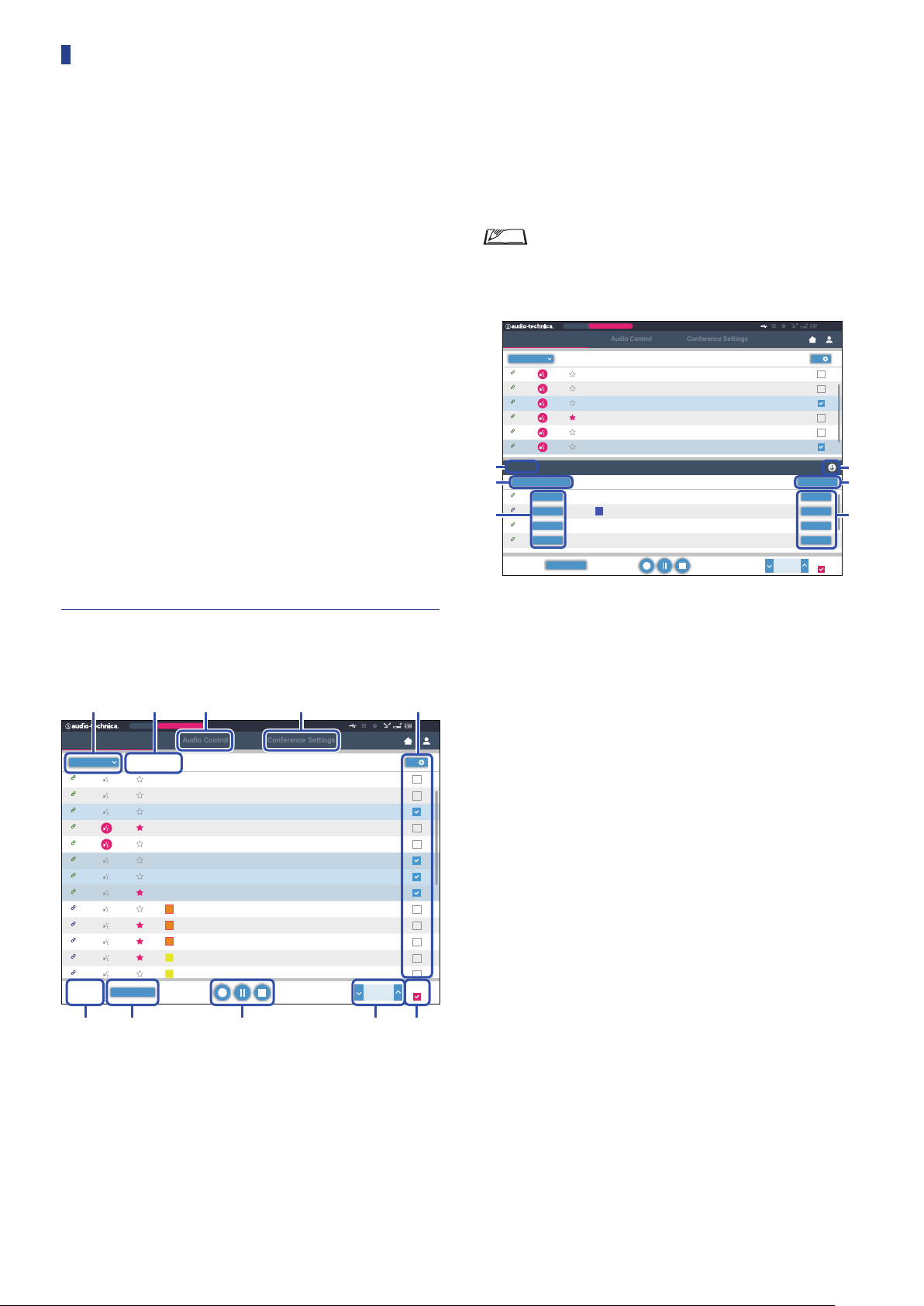
Operating and controlling
Audio Control
Conference Settings
① *1 ② ③ ④*2 *2
⑦ ⑧ ⑨⑥⑤
Audio Control
Conference Settings
④
⑤
⑥
①
②
conferences ([Start Conference])
The [Start Conference] screen is displayed by clicking [Start
Conference] (
from [Setup Conference].
Operate and control a conference underway. You can also change
detailed settings of the conference underway.
Using the tabs on the upper side of the screen, conference mode can
be switched between the following 3 modes.
[Conference Manager]
1
• Settings and management for attendees
• Utterance control
• DU/IU detailed settings
[Audio Control]
2
• Speech output level adjustment
• Conference recording operations
• Audio playback operation such as chime
[Conference Settings]
3
• Conference mode settings and various detailed settings
• Audio playback settings such as chime
page 35) or after finishing conference settings
➤
Perform the recording operations. See “Recording operations”
⑦
page 58
(
Click repeatedly to adjust the volume level. Click the up/down
⑧
).
➤
buttons to adjust the volume level for OUTPUT 1. By ticking the
checkbox ⑨, the level can be adjusted in [Step x10] increments.
*1 From the [Conference Manager] screen, the [Priority] and [Color]
settings are not configurable.
*2 When the Operator access authority is set to [Limited], these items
are not displayed.
• The operation and setting items other than ① to ⑨
described above are the same as the items on the [DU/
IU Settings] screen (
page 56).
➤
When in Request Talk Mode:
Preset
Priority
All Talk OFF
Monthly Sales Meeting
Color
Color
00:32:10
-00:27:50
Delegate Name
Dong Wang
Cai Zhang
Jing Li
Kohei Matsuda
Santiago Hernandez
Linh Thi Nguyen
Delegate Name
Allan Kwouk
Rimma Mashkovtsev
Tomoyuki Murase
Baldur Fechner
Conference Manager
Active
93
50 I U
94
50 I U
95
50 I U
96
50 I U
97
50 I U
98
50 I U
Request
5
Permit Next All Cancel
15
Permit
50 I U
120
Permit
50 DU
③
40
Permit
50 I U
10
Permit
50 I U
10 / 10
Active
Output 1
-40.0
ATUC-50
2
Cancel
Cancel
Cancel
Cancel
Step x10
dB
Operating conferences ([Conference
1
Manager])
Preset
Priority
All Talk OFF
Monthly Sales Meeting
Color
00:32:10
-00:27:50
Delegate Name
Dong Wang
Cai Zhang
Jing Li
Kohei Matsuda
Santiago Hernandez
Linh Thi Nguyen
Lucia Garcia
Emma Smith
Ben Muller
Alexander Smirnov
Raj Kumar
Lee Kim
Miguel Silva
Output 1
Conference Manager
All
93
50 I U
94
50 I U
95
50 I U
96
50 I U
97
50 I U
98
50 I U
99
50 I U
100
50 I U
101
50 DU
102
50 DU
103
50 DU
104
50 DU
105
50 DU
Active
2 / 10
-40.0
In Request Talk Mode, in addition to the DU/IU list, the list of DUs
requesting to talk can also be displayed.
The number of DUs requesting to talk
①
Permits the DU on the top of the list to talk
②
Permits the corresponding DU to talk
③
Opens/closes the request list
④
Cancels all requests to talk
ATUC-50
4
Step x10
dB
⑤
Cancels request to talk from the corresponding DU
⑥
Select [All] to display all connected DU/IUs or [Active] to
①
display currently talking speakers.
Displays the [Audio Control] screen (
②
Displays the [Conference Settings] screen (
③
Displays the [DU/IU Detail Settings] screen (
④
Indicates the number of speakers currently talking. The
⑤
page 58).
➤
➤
page 58).
page 56).
➤
numerator is the number of people speaking and the
denominator is the maximum number of people that can speak at
one time.
Cuts short all currently talking DU/IU users.
⑥
57
Page 58
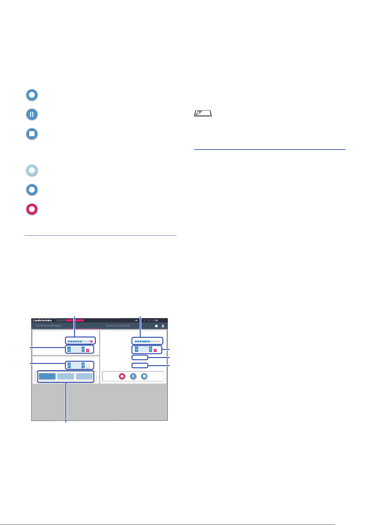
Recording operations:
Conference Manager
Conference Settings
① ⑤
⑦
⑥
②
③
⑧
④
Recording operations such as starting and stopping recording can be
performed either on the [Conference Manager] screen or on the
[Audio Control] screen (
page 58). On the [Audio Control]
➤
screen, you can both configure the advanced audio-related settings
and perform audio operations.
Perform the recording operations using the following 3 buttons
available at the bottom of the [Conference Manager] screen.
Rec button
Starts recording.
Pause button
Pauses recording.
Stop button
Stops recording.
About button colors:
Buttons in this color cannot be operated.
button plays the corresponding audio file. Click the button again
to stop playing.
This is the recording level meter and indicates the level of the
⑤
voice currently being recorded. (Even in recording pause mode,
the voice level meter activates when detecting voices.)
Adjust the recording level. Be sure not to light up the red
⑥
indicator (PK) of the recording level meter
while adjusting
⑤
the level.
This is the elapsed recording time. In recording stop mode, the
⑦
remaining recording time is displayed instead.
This is the available recording time.
⑧
• The operation and setting items other than
to
①
described above are the same as the items on the
[Conference Manager] screen (
Configuring conference settings
3
page 57).
➤
([Conference Settings])
⑧
Buttons in this color can be operated.
Buttons in this color are currently being operated.
If you press a button, the button turns this color.
Configuring the advanced audio‑
2
related settings and performing audio
operations ([Audio Control])
Click the [Audio Control] tab to proceed to the [Audio Control]
screen.
You can perform the recording operations and configure the
advanced audio-related settings on one screen.
Preset
Monthly Sales Meeting
Audio Control
Output 1 Recording
Level
Level Control
SFX
Level Control
Buzzer 1 Buzzer 2 Chime
-30 0 PK12-12-50 6-6-20-40
-40.0
Level
Step x10
Step x10
Level Control
Elapsed Time
Remaining Time
dB
0.0
dB
-30 0 PK12-12-50 6-6-20-40
00:32:10
00:27:50-
ATUC-50
Step x10
0.0
dB
Click the [Conference Settings] tab to display the [Conference
Settings] screen.
According to the conference control and operation methods, select
conference mode and configure detailed settings.
The operations and settings are the same as [Settings &
Maintenance] → [Install Settings] → [Conference] (
page 45).
➤
This is the OUTPUT 1 level meter and indicates the level of
①
audio output from OUTPUT 1.
Adjust the OUTPUT 1 level. Be sure not to light up the red
②
indicator (PK) of the level meter
Adjust the SFX playback level while checking the level with the
③
while adjusting the level.
①
level meter ① etc.
These are SFX operation buttons. Audio files set from
④
[Conference Settings] are played (
page 55). Pressing an SFX
➤
58
Page 59

Information
Troubleshooting
If a problem should arise, first check the following:
1. Check your connections.
2. Verify that the system is being operated as described in this instruction manual.
3. Check that the external devices are operating properly. Check the operation while the devices are not connected to the CU.
4. Restart your network devices.
If any unit in the system is not operating properly, check the items listed in the table below.
If the symptom is not covered on the checklist b
When you contact us, you may be asked the firmware version. Please check the firmware version by following the procedure below.
To check from Web Remote:
[Settings & Maintenance] → [System Settings] → [Utilities]
or
[Settings & Maintenance] → [System Info]
, contact our sales representative.
elow
To check on the CU display:
Set
→ Log in as
Administrator
or
Operator
ATUC‑50CU
Symptom Cause/Solution Page
Cannot turn on the power.
The connected microphone does not
work.
The sound from the connected speaker
is distorted or cannot be heard.
System Info
→
Check that the AC power cord is connected properly. page 30
Check the connection of the microphone. page 11
Check and adjust the MIC/LINE 1/2 settings.
To check from Web Remote:
[Settings & Maintenance] → [Install Settings] → [CU Audio] → [Input Settings]
To check on the CU display:
Set
→ Log in as
Check the connections of all devices. page 11
Plug the connection cables all the way in. -
Check that the inputs and outputs of all devices are connected properly. page 11
Check that terminal pin assignments (Hot/Cold/GND, etc.) are correct. page 11
Check that the cables are not damaged. -
Check and adjust the setting of the connected amplifier. -
Administrator
Operator
or
Audio Setting
→
page 42
page 10
Cannot record sound.
Although recording has performed
properly, when playing the recorded
files using a device such as a
computer, no sound is heard.
Check the remaining memory on the USB device (mass storage device). -
Reconnect the USB device (mass storage device) or try with a different USB device
(mass storage device).
Check that the recording channel set from [Rec source] is correct.
To check from Web Remote:
[Settings & Maintenance] → [Install Settings] → [Recorder] → [USB Recorder
Settings]
To check on the CU display:
Set
→ Log in as
Administrator
Operator
or
Recorder Setting
→
page 53
page 10
59
-
Page 60
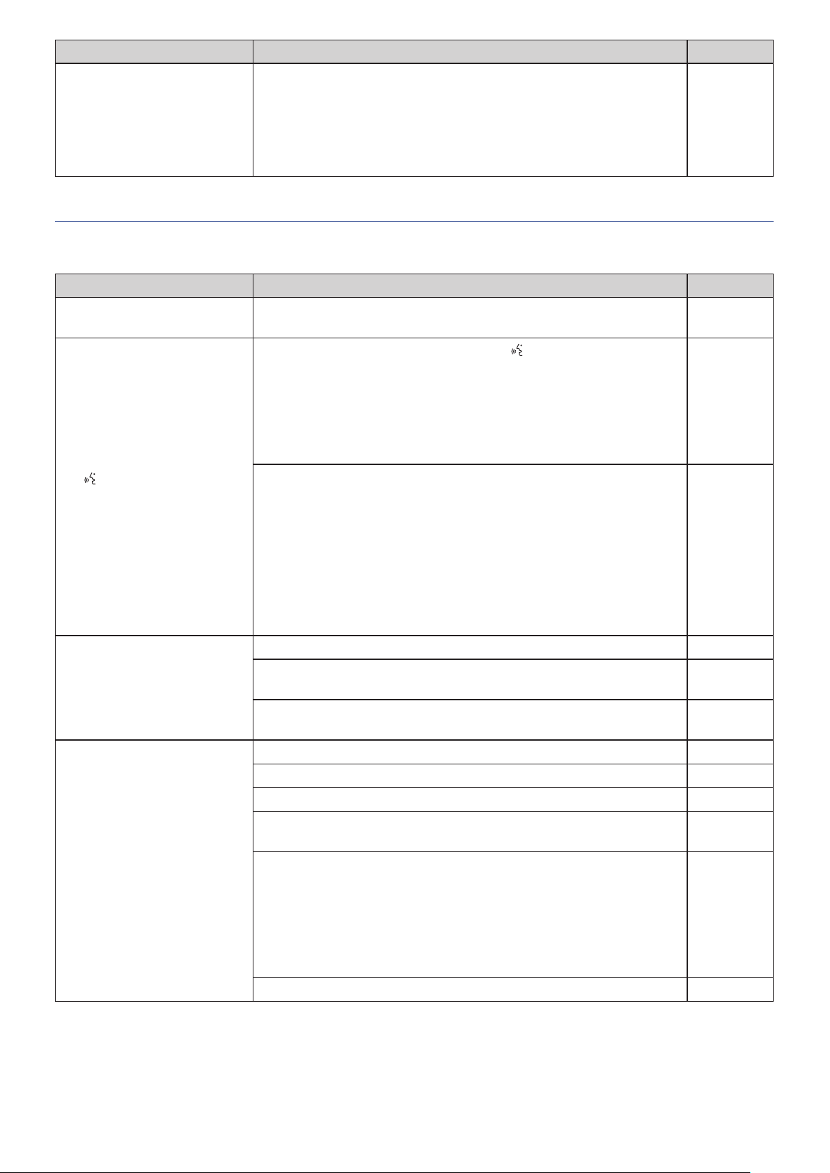
Symptom Cause/Solution Page
Follow the procedure below to reset the password.
Display the HOME screen of the CU display and then while pressing the BACK
①
You forget the password.
button on the CU front panel, rotate the jog dial clockwise until it clicks 3 times.
While pressing the BACK button, rotate the jog dial counterclockwise until it
②
clicks 3 times.
While pressing the BACK button, press the ENTER button.
③
ATUC‑50DU/INT
Symptom Cause/Solution Page
Cannot turn on the power. Check the connection to the CU or other DUs/INTs.
page 9
pages 26,
27
The
(talk) button does not
function.
No sound is output from the
headphone jack.
No sound is output from the built-in
speaker.
Depending on the conference mode or setting, the
Check the conference mode settings.
To check from Web Remote:
[Settings & Maintenance] → [Install Settings] → [Conference] → [Conference Mode]
To check on the CU display:
Set
→ Log in as
The settings of the interpretation unit(s) may cause speech to be output incorrectly,
even if the talk button is pressed to speak. Check the settings of the interpretation
unit(s).
[Settings & Maintenance] → [Install Settings] → [Interpretation]
Settings] → [Interpretation Mode]
and
[Settings & Maintenance] → [Install Settings] → [Interpretation]
Settings] → [Interpretation Languages]
Insert the headphone plug all the way in. -
Raise the volume with the + button.
Use the monitor channel selection button(s) of the DU/INT to confirm that you can
monitor speech from the channel you want.
Check the connection of the DUs. page 27
Plug the Ethernet cable all the way in. -
Check that the cables are not damaged. -
From [Settings & Maintenance] → [Install Settings] → [DU/IU] → [DU/IU Detail
Settings], check that the [Speaker] setting is set to [Enabled].
Adjust the speaker level.
Administrator
Operator
or
Conference Mode
→
To check from Web Remote:
[Settings & Maintenance] → [Install Settings] → [DU/IU] → [Global DU Settings] →
[Speaker Level]
(talk) button may not function.
→
[Interpretation
→
[INT Unit
page 45
page 10
page 51
pages 12,
13
pages 12,
13
page 48
page 46
To check on the CU display:
Set
→ Log in as
Speech is not output from the built-in speaker of the INTs. -
Administrator
Operator
or
Audio Setting
→
DU SP Output Lvl
→
page 10
60
Page 61

Symptom Cause/Solution Page
The ATUC-M does not operate.
Insert the ATUC-M connector into the microphone jack on the DU/INT until a
clicking sound is heard.
From [Settings & Maintenance] → [Install Settings] → [DU/IU] → [DU/IU Detail
Settings], check the setting of [Microphone].
From [Settings & Maintenance] → [Install Settings] → [Interpretation] → [INT Unit
Settings] → [INT Unit Detail Settings] check the setting of [Microphone].
• Check that [Phantom Power] is not set to [Off ].
• Check that [Input Gain] is not too low.
page 30
page 48
page 52
If you read the preset, the settings
changed from the last settings.
Web Remote
Symptom Cause/Solution Page
“Locate” does not recognize the CU
that you want to control via Web
Remote.
The CU you want to control via Web
Remote is grayed out on “Locate.”
Cannot start Web Remote on your
control device such as a tablet or iPad.
You forget the password.
Check that the preset data is correct. page 54
Check that the number and topology of the DUs/INTs have not changed since the
last time.
Check the connections of units including the CU and the control device such as a
computer.
Check that the CU and the control device such as a computer are connected to the
same network.
When multiple CUs are cascaded and CU LINK is functioning, the CU(s) is grayed
out on “Locate” while it is set to [Extension] from [General] → [CU Link Settings] →
[Primary/Extension].
Check the setting again.
Check that the control device is connected to a correct access point. -
Check that the CU and the control device such as a tablet or iPad are connected to
the same network.
Follow the procedure below to reset the password.
Display the HOME screen of the CU display and then while pressing down the
①
BACK button on the CU front panel, rotate the jog dial clockwise until it clicks 3
times.
While pressing down the BACK button, rotate the jog dial counterclockwise until
②
it clicks 3 times.
While pressing the BACK button, press the ENTER button.
③
page 54
page 31
-
page 37
-
page 9
ATUC‑50IU
Symptom Cause/Solution Page
Cannot turn on the power. Check the connection to the CU or other DUs/INTs.
ATLK‑EXT165
Symptom Cause/Solution Page
Cannot turn on the power.
Check that the AC power cord is connected properly. page 30
61
pages 26,
27
Page 62

Error messages
• Error messages displayed on the Web Remote screen and CU displays are as follows.
• The states of the CU LED error indicators are described together with the CU display error messages.
• If the same error persists even after the following remedies are taken, or when the unit(s) requires repair or parts replacement, contact our
sales representative.
Web Remote
Resume Data Error Resume Data Err Failed to read the resume information.
1
Preset Data Error Pst Data Err Failed to read the preset data.
2
DU Power Error DU Power Err
(DU CHAIN: blinks green)
3
DU Communication Error DU Comm Err
4
DU Ring to Daisy DU Ring to Daisy
5
DU Daisy to Ring DU Daisy to Ring
6
Number of DU Decreased DU Number Decrease
7
DU Exceeds 100 Units DU Exceeds 100pcs
8
INT Unit Exceeds 6 Units INT Exceeds 6pcs
9
DU A/B: Exceeds 50 Units DU A/B Exceeds 50pcs
10
DU C/D: Exceeds 25 Units DU C/D Exceeds 25pcs
11
CU Communication Error CU Comm Err
12
CU Link OFF CU Link OFF
13
Network Communication
Error
14
(DU CHAIN: blinks green)
(DU CHAIN: blinks green)
(DU CHAIN: blinks green)
(DU CHAIN: blinks green)
(DU CHAIN: blinks green)
(DU CHAIN: blinks green)
(DU CHAIN: blinks green)
(DU CHAIN: blinks green)
(CU LINK: blinks green)
(CU LINK: blinks green)
Network Comm Err
(REMOTE: blinks green)
CU display
(LED indicators)
State/remedies
• The unit was started up using the second from the last setting or default
setting. Although there is no functional limitation, be sure to restart the unit
to check that the same error does not occur again.
• This error may occur when you recall the default preset or the preset which
you successfully recalled last time. Although there is no functional
limitation, be sure to restart the unit to check that the same error does not
occur again.
An error occurred when power was supplied to the DU.
• Voltage may fall at the 48V output.
After disconnecting all DUs from the CU, restart the CU. If the same error
①
occurs again, the CU requires repair.
If the same error does not occur again in ① but the error occurs again after
②
connecting the DUs, there may be a damaged cable or DU. Identify the
damaged cable or DU for replacement or repair.
DU individual settings cannot be configured.
• Check that there is no DU connection error.
The DU topology has been changed (from ring to daisy).
• If this error occurs even though you did not change the DU connection,
check that there is no DU connection error.
The DU topology has been changed (from daisy to ring).
• If this error occurs even though you did not change the DU connection,
check that there is no DU connection error.
The number of connected DUs decreased.
• If this error occurs even though you did not change the DU connection,
check that there is no DU connection error.
More than 100 DUs are connected to the DU CHAIN A/B/C/D terminals in
total.
• Connect 100 DUs or less to each CU.
More than 6 INTs are connected to the DU CHAIN A/B/C/D terminals in
total.
• Connect 6 INTs or less to CU.
More than 50 DUs are connected to the DU CHAIN A/B terminals in total.
• Connect 50 DUs or less to the DU CHAIN A/B terminals in total.
More than 25 DUs are connected to the DU CHAIN C/D terminals in total.
• Connect 25 DUs or less to the DU CHAIN C/D terminals in total.
A communication error occurred between the CUs.
• Check that there is no CU connection error.
CU Link is cancelled.
• If this error occurs unexpectedly, check that there is no CU connection error.
(1) A network communication error occurred.
(2) An IP command communication error occurred.
• Check that there is no network connection error.
62
Page 63

Web Remote
USB Access Error USB Access Err An error occurred when accessing the USB device (mass storage device).
15
USB Format Error USB Format Err There is a problem with the USB device (mass storage device).
16
Failed Failed (1) The setting cannot be configured due to some system errors.
17
File Export Failed (4) The preset data cannot be exported.
18
File Import Failed (5) The preset data cannot be imported.
19
USB Write Error USB Write Err The data log cannot be saved onto the USB device (mass storage device).
20
Failed. Please turn power OFF. CU FW Update Err
21
Failed. Please turn power OFF. DU FW Update Err
22
Failed. Please turn power OFF. INT FW Update Err
23
Please Turn Pwr OFF
Please Turn Pwr OFF
Please Turn Pwr OFF
CU display
(LED indicators)
State/remedies
• Check that the USB device (mass storage device) has no problems.
• Check that the same error does not occur with another USB device (mass
storage device).
• Check the format of the USB device (mass storage device).
• Use a USB device (mass storage device) formatted with FAT16 or FAT32.
• Try to configure the setting again and check whether the same error occurs
again.
(2) Playback operation cannot be performed.
• Check that the USB device (mass storage device) is connected properly.
• Check that the file you want to play is in the USB device (mass storage
device).
• Check that the format of the file you want to play is correct. (You can check
by, for example, playing the file with another playback device.)
(3) Recording operation cannot be performed.
• Check that the USB device (mass storage device) is inserted in the CU.
• Check that write protection is disabled on the USB device (mass storage
device).
• Check the space available on the USB device (mass storage device).
• Check that the USB device (mass storage device) has no problems.
• Check that the same error does not occur with another USB device (mass
storage device).
• Check that the USB device (mass storage device) has no problems.
• Check that the same error does not occur with another USB device (mass
storage device).
• Check that the USB device (mass storage device) has no problems.
• Check that the same error does not occur with another USB device (mass
storage device).
• Check that the USB device (mass storage device) is inserted to the CU.
• Check that write protection is disabled on the USB device (mass storage
device).
• Check the space available on the USB device (mass storage device).
• Check that the USB device (mass storage device) has no problems.
• Check that the same error does not occur with another USB device (mass
storage device).
An error occurred during the CU firmware update.
• Turn off the power and restart the CU.
An error occurred during the DU firmware update.
• Turn off the power and restart the CU.
(When the update cannot be performed for the 1st DU, or an error occurs
during the update process and the update cannot be continued.)
An error occurred during the INT unit firmware update.
• Turn off the power and restart the CU.
(When the update cannot be performed for the 1st INT, or an error occurs
during the update process and the update cannot be continued.)
63
Page 64

Web Remote
Failed. Please turn power OFF. IU FW Update Err
24
Completed except serial
numbers below.
Please turn power OFF.
XXXXXXXX
25
XXXXXXXX
(Displays a list of 8-digit serial
numbers of DUs for which the
update cannot be performed.)
Completed except serial
numbers below.
Please turn power OFF.
XXXXXXXX
26
XXXXXXXX
(Displays a list of 8-digit serial
numbers of INTs for which the
update cannot be performed.)
Completed except serial
numbers below.
Please turn power OFF.
XXXXXXXX
27
XXXXXXXX
(Displays a list of 8-digit serial
numbers of IUs for which the
update cannot be performed.)
Data acquisition error. Data Acquisition Err Failed to acquire data through operation via Web Remote or the CU display.
28
Unable to Set Unable to Set (1) Unusable characters are contained in the string of letters you have entered.
29
Please Turn Pwr OFF
Part of DU Failed
Please Turn Pwr OFF
Part of INT Failed
Please Turn Pwr OFF
Part of IU Failed
Please Turn Pwr OFF
Can’t.ReducePriority
CU display
(LED indicators)
State/remedies
An error occurred during the IU firmware update.
• Turn off the power and restart the CU.
(When the update cannot be performed for the 1st IU, or an error occurs
during the update process and the update cannot be continued.)
The DU firmware update has been completed but the update cannot be
performed for some DUs.
The serial numbers of DUs for which the update cannot be performed will
①
be listed on the pop-up screen. Write them down.
Turn off the power.
②
Disconnect the DUs with the serial numbers you wrote down.
③
Perform emergency update for the DUs you disconnected in step ③.
④
For details on how to perform the emergency update, contact our sales
representative.
The INT unit firmware update has been completed but the update cannot be
performed for some INTs.
The serial numbers of INTs for which the update cannot be performed will
①
be listed on the pop-up screen. Write them down.
Turn off the power.
②
Disconnect the INTs with the serial numbers you wrote down.
③
Perform emergency update for the INTs you disconnected in step ③.
④
For details on how to perform the emergency update, contact our sales
representative.
The IU firmware update has been completed but the update cannot be
performed for some IUs.
The serial numbers of IUs for which the update cannot be performed will
①
be listed on the pop-up screen. Write them down.
Turn off the power.
②
Disconnect the IUs with the serial numbers you wrote down.
③
Perform emergency update for the IUs you disconnected in step ③.
④
For details on how to perform the emergency update, contact our sales
representative.
• Perform the operation again and check whether the same error occurs.
• Delete unusable characters.
(2) The change cannot be applied because the entered values are out of the
permitted range or the change is not allowed.
• Enter values within the permitted range.
• Check that the unit is in a state where changes are allowed and then perform
the operation again and check whether the same error occurs.
(3) The setting of [Number of Open Mics] (
the current number of priority DUs.
• Set a different number for [Number of Open Mics] (
number of priority DUs.
All DUs will be turned off to
apply the changes. Do you wish
to proceed?
30
Unable to control. Unable to Ctrl (1) Since recording, recording pause, or file reading process is under way, the
31
Turn OFF All DU?
(4) Since recording, recording pause, or file reading process is under way, any
recording-related settings cannot be configured.
• Stop recording and then perform the operation again.
(5) You must turn off the microphones for all of the DUs in order to change
the settings.
• Selecting [Yes] forces the microphones for all of the DUs off and changes the
settings.
operation cannot be performed.
(2) Due to other reasons, the operation cannot be performed. (Operations
except changing settings cannot be performed.)
• Stop recording and then perform the operation again.
NOM
) cannot be changed due to
NOM
) or change the
64
Page 65

Web Remote
Number of priority units
exceeds maximum. Reduced
32
priority channels.
Unable to set. Number of
priority channels exceeds
33
maximum.
Recording Failed
34
35 -
36 -
37 -
38 -
CU display
(LED indicators)
-
-
-
Boot Error XXX An error occurred while booting the CU. (XXX indicate an error code.)
Chg to FreeTalk Mode Since a communication error occurred with the control device, the conference
Forcible FW Update Emergency update executes for the CU.
Connect USB Device
with FW Update File
State/remedies
The number of DUs which are set as priority DUs exceeded the limit due to
CU Link. Decrease the number of priority DUs. (Deactivate the priority
setting for some DUs.)
• Check the priority DUs and change the setting as necessary.
The maximum number of DUs that can be designated as priority DU is 1 unit
less than the specified value for [Number of Open Mics] (
DUs can be designated as a priority DU.
• Change the setting value for the NOM or DU priority setting.
A recording function error occurs such as a recording error not due to
recording operations via Web Remote.
• Check that no error occurs during recording on the CU. If an error occurs,
solve the problem according to the error.
• Restart the CU and check whether the same error occurs. If the same error
occurs again, the CU requires repair.
mode will be switched to Free Talk Mode where you do not need the control
device.
• Check that there is no network connection problem.
• Follow the message displayed and do not turn off during the update.
Emergency update executes (for the CU or the DU).
• Insert a USB control device (mass storage device) where the firmware is
stored to the CU.
NOM
). No more
65
Page 66

Specifications
ATUC-50CU specifications
General specifications
Inputs Mic/Line×2, AUX (ST)×1, INTERPRETATION RETURN×2
I/O Connectors
Outputs BAL.×4, UNBAL.×1
LINK/CHAIN DU A/B terminals, CU A/B terminals (DU C/D terminals)
Recording(*1)
Playback(*1)
Signal delays
Frequency response +1.0, –2.0dB 20Hz - 20kHz, refer to +4dBu output @1kHz.
Dynamic range 110dB A-Weighted
Signal to noise 90dB A-Weighted
Headroom 20dB
Equivalent input noise Mic/Line 1-2 Less than –126dBu Rs=150ohm
Residual noise Less than –86dBu A-Weighted
Total harmonic distortion Less than 0.03% 1kHz unity
Crosstalk @1kHz Less than –80dB
OLED display 20 × 2 Character type, Color: Yellow
Phantom power DC+48V
Power requirement AC 100V-240V 50/60Hz
Power consumption
Operation guaranteed temperature range 0-40°
Via USB storage device
MP3 bit rate 64kbps/128kbps/192kbps/256kbps/320kbps
Data length 16bit, 24bit
WAV
Sampling frequency 48kHz
Bit rate 32-320kbps
MP3(*2)
Sampling frequency 48kHz
Maximum file size 2GB
Maximum number of files 30files
1/2/3/4 track (WAV) (BWF standard)
1/2 track (MP3) (Original format)
MIC Input to Output: 1ms
DU to CU: 1.2ms
20W-175W (max.), Connecting 50 ATUC-50DUs is equivalent to
2.55A.
C
Operation guaranteed humidity range 25-85%
External dimensions (W × D × H) 482.6mm × 331.6mm × 44mm
Net Weight 3.4kg
Finish
Included Accessories
*1 Supported file systems: FAT16/FAT32
*2 Supported format: MPEG-1 Audio Layer-3.
Front panel Black
Top & Rear Black
AC power cord, Quick Setup Guide ×2, Euroblock connectors ×9,
Warranty
66
Page 67

Input/output specifications
Analog input specifications
Input Terminals Gain
MIC/LINE
Input 1-2
AUX Input LR (Mono ×2) - 10k ohm -
INTERPRETATION
RETURN 1-2
* Default setting
Mic 15-59dB 5k ohm –60dBu –40dBu –16dBu Euroblock Balanced
Line 15-59dB 20k ohm –40dBu
- 20k ohm -
Load
Impedance
Minimum Unity Maximum
Input Level
+4dBu*/
0dBu
0dBV*/
–10dBV/
–20dBV
+4dBu*/
0dBu
+24dBu*/
+20dBu
+20dBV*/
+10dBV/
0dBV
+24dBu*/
+20dBu
Connector
Euroblock Balanced
RCA Pin Unbalanced
Euroblock Balanced
Balanced/
Unbalanced
Analog output specifications
Output Terminals Load Impedance
BAL. (Balanced) Output 1-4 150ohm - +4dBu +24dBu RCA Pin Balanced
UNBAL. (Unbalanced)
Output 1
300ohm - 0dBV +20dBV Euroblock Unbalanced
Minimum Unity Maximum
Output Level
Connector
Balanced/
Unbalanced
Digital input/output specifications
Terminals Format
USB USB 24bit/48kHz Playback: MP3 or WAV/Record: MP3 or WAV USB (A type)
DU CHAIN A/B (C/D) Original format 24bit/48kHz Floor, Return, Interpretation language, Active Mic R J-45
CU LINK A/B Original format 24bit/48kHz Floor, Return, Interpretation language, Active Mic RJ-45
Data length/Sampling
Frequency
Audio Connector
Control I/O specifications
Terminals Format Level Connector
NETWORK IEEE802.3 10BASE-T/100BASE-TX RJ-45
67
Page 68

ATUC-50DU/INT specifications
General specifications
Inputs Microphone jack×1
I/O connectors
Sampling frequency 24bit/48kHz
Frequency response +1.0, –2.0dB 20Hz - 20kHz, refer to +4dBu output @1kHz.
Dynamic range 107dB A-Weighted
Signal to noise 87dB A-Weighted
Headroom 20dB
Equivalent input noise Less than –121dBu Rs=150ohm
Total harmonic distortion Less than 0.07% 1kHz unity
Phantom power DC+24V
Power requirement DC+48V
Power consumption 2.2W
Operation guaranteed temperature range 0-40°C
Operation guaranteed humidity range 25-85%
External dimensions (W × D × H) 135mm × 148.3mm × 84.2mm
Net Weight 570g (900g including the optional bottom weight)
Outputs Headphone jack×1
CHAIN DU/CU connection terminals
Finish
Included Accessories Quick Setup Guide, Warranty
Top panel Gun metal
Enclosure Black
68
Page 69

Input/output specifications
Analog input specifications
Input Terminals Gain
MIC Input 7-47dB 5k ohm –60dBu –40dBu –20dBu XLR female Balanced
Load
Impedance
Minimum Nominal Maximum
Input Level
Connector
Analog output specifications
Output Terminals Load Impedance
Minimum Nominal Maximum
Headphones 32ohm - 1.5mW 15mW φ3.5mm Stereo
Speaker 8ohm - 50mW 100mW -
Output Level
Connector
Digital input/output specifications
Terminals Format
DU CHAIN A/B Original format 24bit/48kHz Floor, Return, Interpretation language, Active Mic RJ-45
Data length/Sampling
Frequency
Audio Connector
Control I/O specifications
Terminals Format Level Connector
Option port UART +5V, TX, RX, GND RJ-11
Balanced/
Unbalanced
69
Page 70

ATUC-50IU specifications
General specifications
Inputs
I/O connector
Data length/Sampling frequency 24bit/48kHz
Frequency response +1.0 - 2.0 dB, 20 Hz - 20 kHz (+4 dBu output at 1 kHz)
Dynamic range 106 dB, A-Weighted
S/N ratio 86 dB, A-Weighted
Headroom 20 dB
Noise equivalent input Less than –125 dBu, Rs = 150 Ω
Total harmonic distortion Less than 0.07%, 1 kHz unity
Phantom Power DC+48V
Power requirement DC+48V
Power Consumption 3.4 W
Operation guaranteed temperature range 0 - 40°C
Operation guaranteed humidity range 25 - 85%
External dimensions (W × D × H) 116 mm × 173 mm × 25 mm
Weight 440g
Included Accessories
Outputs
CHAIN DU/CU connection terminals
Euroblock connector: microphone input terminal × 1 set, operation input
terminal × 6 sets, and general purpose input terminal (GPI) × 8 sets
Euroblock connector: speaker output terminal × 1 set, headphone output
terminal × 1 set, status output terminal × 6 sets, power supply terminal × 1 set,
general output terminals (GPO) × 8
Quick Start Guide, Euroblock connecters × 13 (green × 3, black × 10),
warranty
70
Page 71

Input/output specifications
Analog input specifications
Input Terminals Gain
MIC Input 7 - 47 dB 4k ohm -60 dBu -40 dBu -20 dBu Euroblock Balanced
Load
Impedance
Minimum value Nominal value Maximum value
Input Level
Connector
Analog output specifications
Output Terminals Load Impedance
Minimum value Nominal value Maximum value
Headphones 32 ohm - 1.5 mW 15 mW Euroblock
Speaker 8 ohm - 50 mW 100 mW Euroblock
Output Level
Connector
Digital input/output specifications
Terminals Format
DU CHAIN A/B Original format 24 bit/48 kHz Floor, Return, Interpretation language, Active Mic RJ-45
Data length/Sampling
frequency
Audio Connector
Control I/O specifications
Terminals Connector
Operation input terminal Euroblock
Status output terminal Euroblock
General purpose input/output terminal Euroblock
Balanced/
unbalanced
71
Page 72

ATLK-EXT165 specifications
General specifications
I/O connector
Power supply 100 - 240 VAC, 50/60 Hz
Power Consumption 15 - 160 W (max.); 50 ATUC-50DUs is equivalent to 2.55 A
Operation guaranteed temperature range 0 - 40 °C
Operation guaranteed humidity range 25 - 85%
External dimensions (W × D × H) 217 mm × 325 mm × 40.5mm
Weight 2.1 kg
Included Accessories Quick Start Guide, Euroblock connector × 1 (black), table mount, warranty
LINK POWER STATUS Euroblock connector (3 pins)
CHAIN DU/CU connecter terminals (RJ-45 × 2)
72
Page 73

ATUC-M specifications
ATUC-M43H ATUC-M58H
Type Back electret type
Directional characteristics Hyper-cardioid
Frequency characteristics 100-15,000Hz
Sensitivity (0dB=1V/1Pa, 1kHz) –40dB
Maximum input sound pressure level
(1kHz, THD1%)
Signal-to-Noise ratio (1kHz, 1Pa) 64dB or more
Output impedance 250ohms balanced
Finish Mat black baking paint finish
External dimensions 18.9mm diameter×430mm 18.9mm diameter×580mm
Weight Approx. 82g Approx. 92g
134dB S.P.L.
73
Page 74

Audio-Technica Corporation
http://www.audio-technica.com/world_map/
©2017 Audio-Technica Corporation
2017.10
 Loading...