

Page 1
SPECIAL PURPOSE MICROPHONES
Description
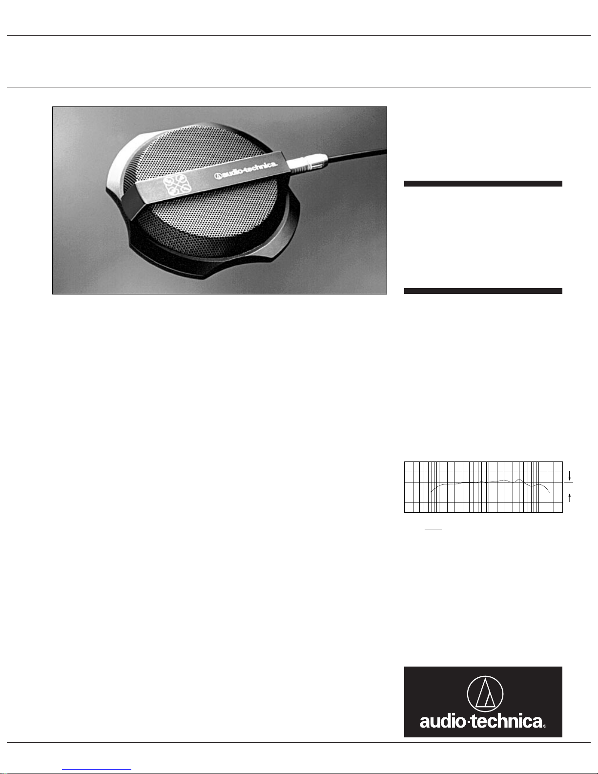
The AT854R is a multi-channel boundary
microphone with four cardioid condenser
elements mounted in a single housing. It is
ideal for high-quality sound reinforcement and
a variety of video and audio conferencing
applications, especially when used with an
Audio-Technica automatic SmartMixer
®
. Its
low-profile design makes the AT854R suitable
for use in applications where minimum visibility is required.
The four channels of the AT854R, mounted in
quadrants, are separate and independent.
They can be powered and used individually or
in any combination. This permits system
integrators to use their own proprietary DSP
algorithms for microphone control when
incorporating the AT854R into an existing system.
Positioning a properly designed boundary
microphone centrally on a large, flat, unobstructed surface yields several distinct advantages. Directionality of the individual
elements is increased by 3 dB, promoting
enhanced gain before feedback and further
suppression of ambient noise. Sensitivity is
increased for improved signal-to-noise ratio.
Phase distortion due to reflected sound energy
from the boundary itself is eliminated.
The AT854R requires 9-52V DC phantom
power for each operating channel. A 30'
(9.1 m) cable with a miniature multi-contact
metal-body plug for connecting to the microphone is included. The cable is custommanufactured with four separate shielded and
jacketed pairs inside a rugged overall jacket.
Its output end has four XLRM-type connectors for plugging into a mixer, allowing individual control of each channel.
The microphone is enclosed in a rugged case
and protected by two layers of perforated
steel. The combination of heavy case and rubber non-slip bottom pad minimizes mechanical coupling of surface vibrations to the
microphone. The low-profile housing has a
low-reflectance black finish.
Installation and Operation
The symmetry and area of the mounting surface directly affect the sensitivity of the
boundary microphone at low frequencies.
Ideally, the mounting surface should be circular;
however, square or rectangular surfaces are
most often used. If the mounting surface is
rectangular, the smaller dimension tends to
determine low-frequency cutoff. The microphone should be centered on the surface and
positioned with the microphone elements facing the sound sources. The sound sources
should not be below, or higher than 60˚ above,
the plane of the mounting surface.
Channel numbers are as shown on the top of
the mic housing. Outputs are low impedance
balanced. The balanced signal appears across
the MiniCon connector’s Pins 2 and 3 for Mic
1, Pins 4 and 5 for Mic 2, Pins 6 and 7 for Mic
3 and Pins 8 and 9 for Mic 4. The ground
(shield) connection for all microphones is
Pin 1. Output is phased so that positive
acoustic pressure produces positive voltage
at the even-numbered pins, which correspond
to Pin 2 of each XLR connector of the supplied
cable. A table on the back of this sheet summarizes cable connections.
While a modern condenser microphone is not
unduly sensitive to the environment, temperature extremes can be harmful. Exposure to
high temperatures can result in gradual and
permanent reduction of the output level.
Avoid leaving the microphone in the open sun
or in areas where temperatures exceed 110˚ F
(43˚ C) for long periods of time. Extremely
high humidity should also be avoided.
Architects and Engineers Specifications
The microphone shall be a four-channel fixedcharge condenser with cardioid polar patterns
designed for use in surface-mount boundary
and conferencing applications. The frequency
response shall be 70 Hz to 16,000 Hz. The
microphone shall operate from an external 9V
to 52V DC phantom power source. Nominal
open-circuit output voltage shall be 14.1 mV at
1 kHz, 1 Pascal. Output shall be low impedance balanced (100 ohms).
A 30' (9.1 m) cable with a miniature multi-contact plug at one end and four XLRM-type connectors at the other shall be supplied for connection between the microphone and electronics inputs. The microphone shall have a
maximum width of 5.91" (150.0 mm), and a
height of 1.09" (27.6 mm). Weight shall be
16.4 oz (465 grams). The microphone shall be
housed in a die-cast case with a two-layer perforated steel grille. Finish shall be lowreflectance black.
The Audio-Technica AT854R is specified.
Frequency Response - Each Channel
Frequency in Hertz
Response in dB
10 dB
20k
10k
5k
2k
1k
500
200100
50
LEGEND
12" or more on axis
AT854R
MULTI-CHANNEL
CONDENSER
BOUNDARY
MICROPHONE
Page 2
AT854R SPECIFICATIONS
†
ELEMENT Fixed-charge back plate
permanently polarized condenser
POLAR PATTERN (EACH CHANNEL) Half-cardioid (cardioid in hemisphere
above mounting surface)
FREQUENCY RESPONSE 70-16,000 Hz
OPEN CIRCUIT SENSITIVITY –37 dB (14.1 mV) re 1V at 1 Pa*
IMPEDANCE 100 ohms
MAXIMUM INPUT SOUND LEVEL 134 dB SPL, 1 kHz at 1% T.H.D.
SIGNAL-TO-NOISE RATIO
1
65 dB, 1 kHz at 1 Pa*
DYNAMIC RANGE (TYPICAL) 105 dB, 1 kHz at Max SPL
PHANTOM POWER REQUIREMENTS 9-52V DC, 2 mA typical (each channel)
WEIGHT 16.4 oz (465 grams)
DIMENSIONS 5.91" (150.0 mm) maximum diameter,
1.09" (27.6 mm) high
OUTPUT CONNECTOR Neutrik MiniCon (9 pins used)
CABLE 30' (9.1 m) long, 0.28" (7.0 mm) diameter
shielded cable with a miniature multi-contact
plug at microphone end and four independent
XLRM-type output connectors
†
In the interest of standards development, A.T.U.S.
offers full details on its test methods to other industry
professionals on request.
* 1 Pascal = 10 dynes/cm2= 10 microbars = 94 dB SPL
1
Typical, A-weighted, using Audio Precision System One.
Optional Accessories:
• CP8201 line matching transformer (Lo-Z to 50,000 ohms).
• AT8202 adjustable in-line attenuator for use with balanced Lo-Z microphones.
• AT8314 2-conductor, shielded, vinyl-jacketed, broadcast-type cable with XLRF-type connector at
microphone end, XLRM-type connector at equipment end. Available in 10', 20', 25', 30', 50' & 100'
lengths.
• CP8506 four-channel 48V phantom power supply (AC powered).
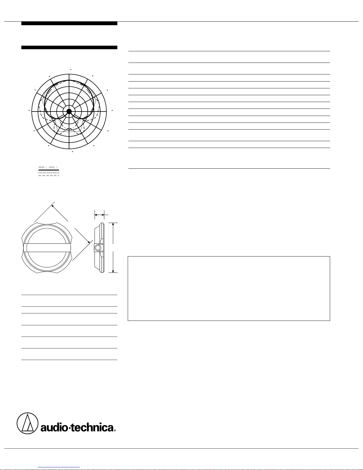
Polar Pattern - Each Channel
Dimensions
LEGEND
8 kHz
5 kHz
1 kHz
200 Hz
SCALE IS 5 DECIBELS PER DIVISION
90
60
120
30
150
210
240
270
300
330
180
0
AT854R
One-Year Limited Warranty
Audio-Technica microphones and accessories purchased in the U.S.A. are warranted for one year from date of purchase
by Audio-Technica U.S., Inc. (A.T.U.S.) to be free of defects in materials and workmanship. In event of such defect, product
will be repaired promptly without charge or, at our option, replaced with a new product of equal or superior value if delivered
to A.T.U.S. or an Authorized Service Center, prepaid, together with the sales slip or other proof of purchase date.
Prior
approval from A.T.U.S. is required for return.
This warranty excludes defects due to normal wear, abuse, shipping damage, or failure to use product in accordance with instructions. This warranty is void in the event of unauthorized repair or
modification.
For return approval and shipping information,
contact the Service Department, Audio-Technica U.S., Inc., 1221
Commerce Drive, Stow, Ohio 44224.
Except to the extent precluded by applicable state law,
A.T.U.S. will have no liability for any consequential, incidental,
or special damages; any warranty of merchantability or fitness for particular purpose expires when this warranty
expires.
This warranty gives you specific legal rights, and you may have other rights which vary from state to state.
Outside the U.S.A., please contact your local dealer for warranty details.
Form No. 0308-0854-00- B/W P50989 © 1997 Audio-Technica U.S., Inc. Printed in U.S.A.
Audio-Technica U.S., Inc., 1221 Commerce Drive, Stow, Ohio 44224
Audio-Technica Limited, Old Lane, Leeds LS11 8AG England
1.09"
27.6 mm
DATA SHEET P10953 / REV. A
5.51"
140.0 mm
5.91"
150.0 mm
Summary of Cable Connections
Wire Color MiniCon XLRM - Pin
Pin No.
Shields All to 1 All XLRMs - Pin 1
Black 2 XLRM 1 - Pin 2
White 3 XLRM 1 - Pin 3
Blue 4 XLRM 2 - Pin 2
Red 5 XLRM 2 - Pin 3
Green 6 XLRM 3 - Pin 2
Gray 7 XLRM 3 - Pin 3
Brown 8 XLRM 4 - Pin 2
Yellow 9 XLRM 4 - Pin 3
 Loading...