

Page 1
Professional
Microphone Accessories
AT8416
MICROPHONE SHOCK MOUNT
Description
The Audio-Technica AT8416 shock mount
effectively isolates mounted microphones
from impact vibration and shock handling
noise. It is intended for use with microphones
mounted on lecterns, pulpits, conference
tables and similar surfaces. Designed especially for UniPoint®gooseneck microphones,
it may be used with other lightweight microphones as well.
The use of a shock mount is particularly
important in any application where wide-range
sound equipment is used, and where highlevel low-frequency sounds can be expected.
The AT8416 shock mount system utilizes two
oversize chloroprene rings, similar to rubber
bands. The rings are
mounted transversely.
An aluminum mounting
stud with 5/8"-27 threads
is held in the central cavity
formed by the opposing
bands, thereby “floating”
the shock mount assembly,
and isolating it from
mechanical coupling to
the resonating surface.
A slot is provided in the
mounting flange to allow
a small-diameter cable to
pass down the mounting
hole. A cable channel
secures the cable in the
flush mount assembly and
helps to further deaden the
transmission of vibration.
When properly installed,
the AT8416 isolates the
microphone from contact with the mounting
surface, and eliminates pickup of low-frequency
resonances caused by mechanical coupling.
This generally allows higher sound reinforcement levels and higher gain-before-feedback.
One-Year Limited Warranty
Audio-Technica microphones and accessories
purchased in the U.S.A.are warranted for one year from
date of purchase by Audio-Technica U.S., Inc. (A.T.U.S.)
to be free of defects in materials and workmanship. In
event of such defect, product will be repaired promptly
without charge or, at our option, replaced with a new
product of equal or superior value if delivered to A.T.U.S.
or an Authorized Service Center, prepaid, together with
the sales slip or other proof of purchase date.
Prior
approval from A.T.U.S. is required for return.
This
warranty excludes defects due to normal wear, abuse,
shipping damage, or failure to use product in accordance with instructions.This warranty is void in the event
of unauthorized repair or modification.
For return approval and shipping information,
contact the Service Department, Audio-Technica U.S.,
Inc., 1221 Commerce Drive, Stow, Ohio 44224.
Except to the extent precluded by applicable state law,
A.T.U.S. will have no liability for any consequential,
incidental, or special damages; any warranty of
merchantability or fitness for particular purpose
expires when this warranty expires.
This warranty gives you specific legal rights, and you
may have other rights which vary from state to state.
Outside the U.S.A., please contact your local dealer for
warranty details.
AT8416 SPECIFICATIONS
DEPTH
MOUNTING FLANGE 0.08" (2 mm)
BODY 1.26" (32 mm)
DIAMETER
MOUNTING FLANGE 2.01" (51 mm)
BODY 1.34" (34 mm)
MOUNTING STUD 0.71" (18 mm)
WEIGHT 2.5 oz (71 grams)
SUSPENSION SYSTEM 2 chloroprene
rings
Audio-Technica U.S.,Inc., 1221 Commerce Drive, Stow, Ohio 44224
Audio-Technica Limited, Old Lane, Leeds LS11 8AG England
Form No.0315-0705-02-B/W © 1996 Audio-Technica U.S., Inc. Printed in U.S.A.
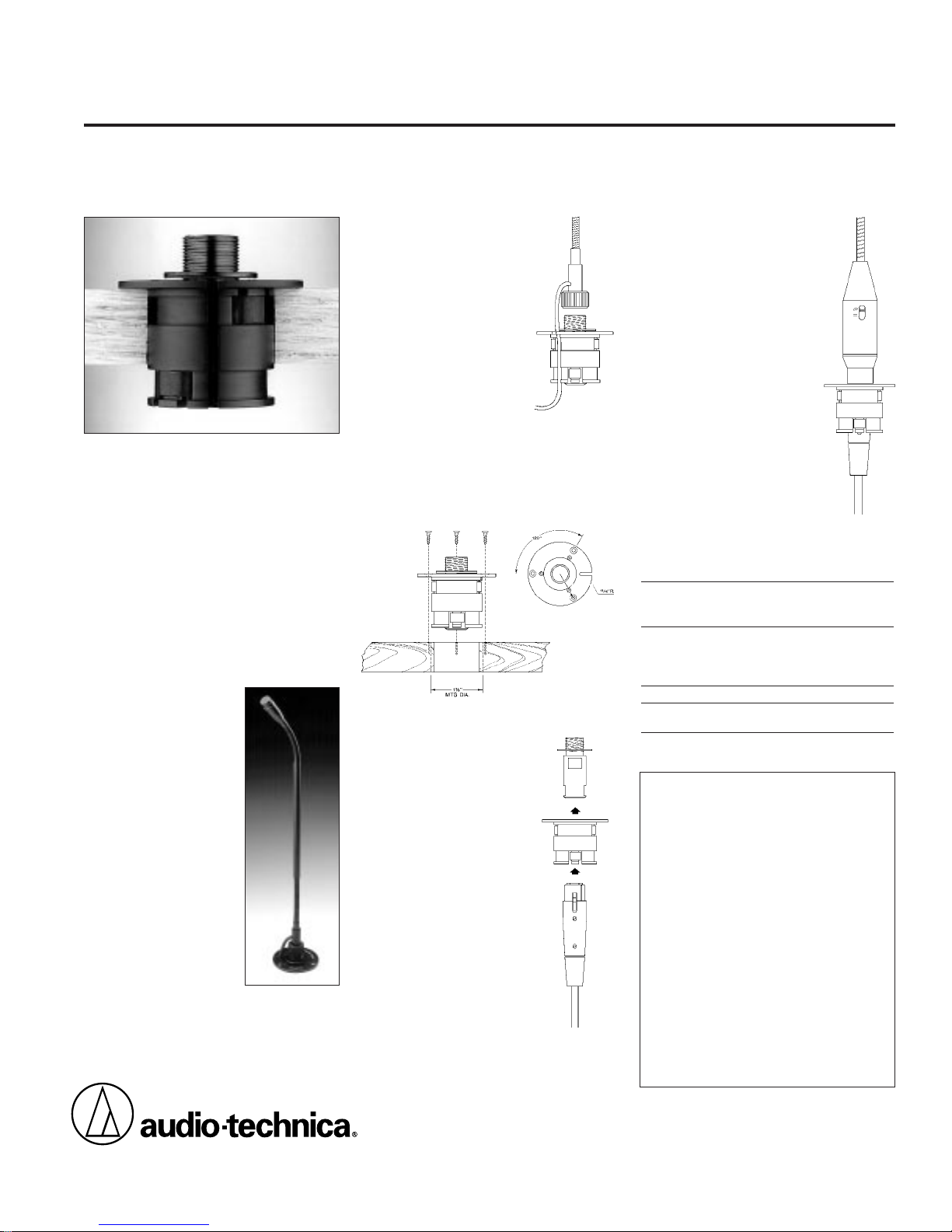
Installation
5
/8"-27 Mount: Drill a 13/8"
hole at the desired point in
the mounting surface. Screw
the base of the microphone
onto the threads of the
mounting stud. Drop the
microphone cable down
through the hole in the
mounting surface, making
certain the cable is captured
by the slot in the mounting
flange and is in place in the
cable channel along the side
of the shock mount (Fig. 1).
Leave some slack in the cable between the
mic and the mounting flange;
pulling the
cable snug will “bypass” the suspension.
Set the shock mount in place, with the cable
slot away from the “front,” and secure with
the three screws provided (Fig 2).
Plug-in Mount: Drill a 13/8"
hole at the desired point in
the mounting surface. Run
the XLRF connector of the
microphone cable up through
the hole. Remove the mounting stud from the AT8416 and
insert the XLRF connector up
through the chloroprene rings
(Fig. 3). Secure the shock
mount with the three screws
provided (as in Fig. 2). Attach
the XLRF connector to the
microphone and work the
connector body back down
into the shock mount (Fig. 4).
Fig. 1
Fig. 2
Since the design of the shock
mount “floats” the microphone,
with no rigid, fixed position, take
care to center the mounting
stud (or connector) in the shock
mount cavity. This will ensure
that the microphone stands
upright. If the microphone
still leans to one side after
installation, the mounting
stud or connector can be
repositioned without damage.
Fig. 3
Fig. 4
Remove
Insert
 Loading...