

Page 1
AEW-R4100
Frequency-agile True Diversity UHF Receiver
Features
• IntelliScan™ automatic frequency scanning and selection on all
linked receivers
• Two compatible frequency bands with 996 selectable channels each
• 25 kHz frequency spacing makes it easier to nd a clear, open
frequency in crowded RF environments
• True diversity receiver with dual IF design for dropout free and
silent, automatic switching
• Up to 40 systems compatible using both bands
• High efciency dual companding system for awless audio
• Digital Tone Lock™ squelch that communicates transmitter data
to the receiver
• Adjustable receiver squelch
• Receiver internal function menu with soft-touch controls
• High visibility white-on-blue LCD receiver status display
• All components store up to ve preset congurations
including names
• Rear panel, front panel or external antenna mount options with
12-volt antenna power
• Balanced and unbalanced outputs with three-position attenuator
• Ground lift switch on balanced output
• Headphone output
• Flexible 1/2 wave antennas supplied for superior range
• Receiver mounts in a single rack space (1 or 2 units)
Description
The AEW-R4100 receiver operates on one of two UHF bands with 996
selectable frequencies. 25 kHz frequency spacing enables the systems
to easily nd an open frequency in crowded RF environments. It is
equipped with IntelliScan® automatic channel assignment system, which
greatly simplies the selection of usable frequencies in a multi-channel
wireless system and eliminates the need for searching for clear channels.
The receiver features true diversity reception with two antennas feeding
two completely independent RF sections. Automatic logic circuitry
continuously compares and selects the superior received signal providing
better sound quality and reducing the potential for dropouts. A unique
dual compander design extends the audio bandwidth of the system and
an advanced digital Tone Lock™ squelch helps minimize interference. In
addition, the Tone Lock signal from the transmitter also conveys information on the transmitter’s battery condition, mute status, and transmitter
name back to the receiver for display. All receiver functions are accessed
via front panel soft-touch controls with lockout capability to prevent
unauthorized access. The receiver’s front panel display provides continuous indication of RF signal strength along with the audio modulation level
of the received signal. Features not often found on other receivers
include high pass lter, meter hold function, adjustable squelch, alert
indicators on the front panel and 12V DC power on the antenna connections for powered RF accessories. A front panel headphone connection
4000 Series artist elite® wireless systems
with level control is provided for audio condence monitoring. Four user
selectable, namable presets allow the ability to store and recall commonly used settings increasing the exibility of the receiver in multi-use
venues. Designed to operate from mains AC, the receiver incorporates a
universal self selecting internal power supply with standard IEC power
connector eliminating the need for a wall wart. Each receiver incorporates
rear-panel connections for balanced XLR and unbalanced 1/4" outputs with
adjustable gain along with detachable BNC 1/2 wave antennas. The
receiver is halfwidth for a standard 1U 19" rack space and includes
rack-mount adapters.
Architect’s and Engineer’s Specications
The frequency-agile automatic scanning FM wireless receiver shall be
designed to operate in UHF bands of either 541.500–566.375 MHz or
655.500–680.375 MHz and shall be capable of operating on any of 996
PLL-synthesized channels per band. The all-metal receiver shall provide an
intelligent automatic scanning and frequency plan building function to select
and coordinate appropriate local usable channels for proper wireless system
operation for all linked receivers. All receiver functions shall be controlled by
soft-touch controls on the receiver front panel. It shall be a true diversity
receiver with two independent internal tuner sections, automatically
selecting the highest quality signal for the receiver’s output. The receiver
shall incorporate a dual compander system for processing high and low
audio frequencies separately. The system will be equipped with an advanced
Tone Lock™ digital identication system to ensure that only the desired wireless microphone transmitter allows the receiver to be un-muted. The receiver
shall have four operator indicators on the front panel: transmitter low battery
warning, signal loss, input overload and transmitter power setting. The receiver shall continuously monitor and display the battery life indicator of the
associated wireless transmitter, the RF signal strength and the selection of
internal dual tuner sections (A&B). A high-visibility white-on-blue receiver
display shall be provided to visually monitor receiver functions and shall be
visible in both bright and low light conditions. The display in conjunction with
front panel soft-touch controls shall be used to congure and set up the
receiver’s operating parameters. It shall be possible to show the receiver or
transmitter name on the display in alphanumeric characters. Four selectable,
namable user presets shall be provided to store and recall receiver parameters. It shall be possible to lock out all receiver front panel controls to
prevent unauthorized operation. A front panel headphone connection with
independent output level control shall be provided for audio condence
monitoring. The receiver shall have a rear panel selector to lift the ground
connection from pin 1 of the XLR-type output connector to prevent ground
loops. A three-position audio output attenuator shall be located on the rear
panel to match the receiver output to ancillary equipment. The receiver shall
be powered by 100–240V AC 50–60 Hz and incorporate a detachable power
cable assembly using standard IEC connections. Antennas shall be located
on the rear of the receiver and shall utilize standard BNC-type connectors to
allow them to be detached from the receiver to facilitate the receiver being
used with external antennas or antenna distribution devices. Switchable 12V
DC antenna power shall be provided to power external active antenna
system devices. The receiver’s design shall provide totally silent audio output
muting when the wireless transmitter is turned off or signal is lost. The
wireless receiver and the supplied metal rack-mounting brackets shall be
industrial black. The receiver shall be rackmountable singly or in pairs in a
single rack space.
The wireless receiver shall be an Audio-Technica AEW-R4100 or equivalent.
Page 2
AEW-R4100
47
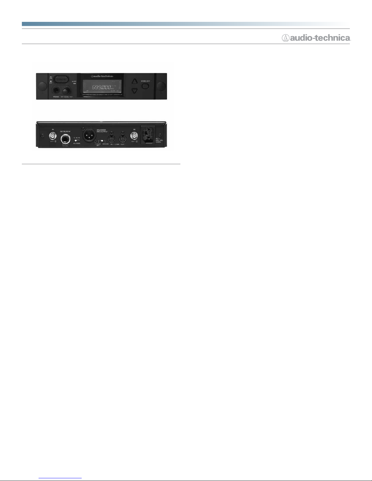
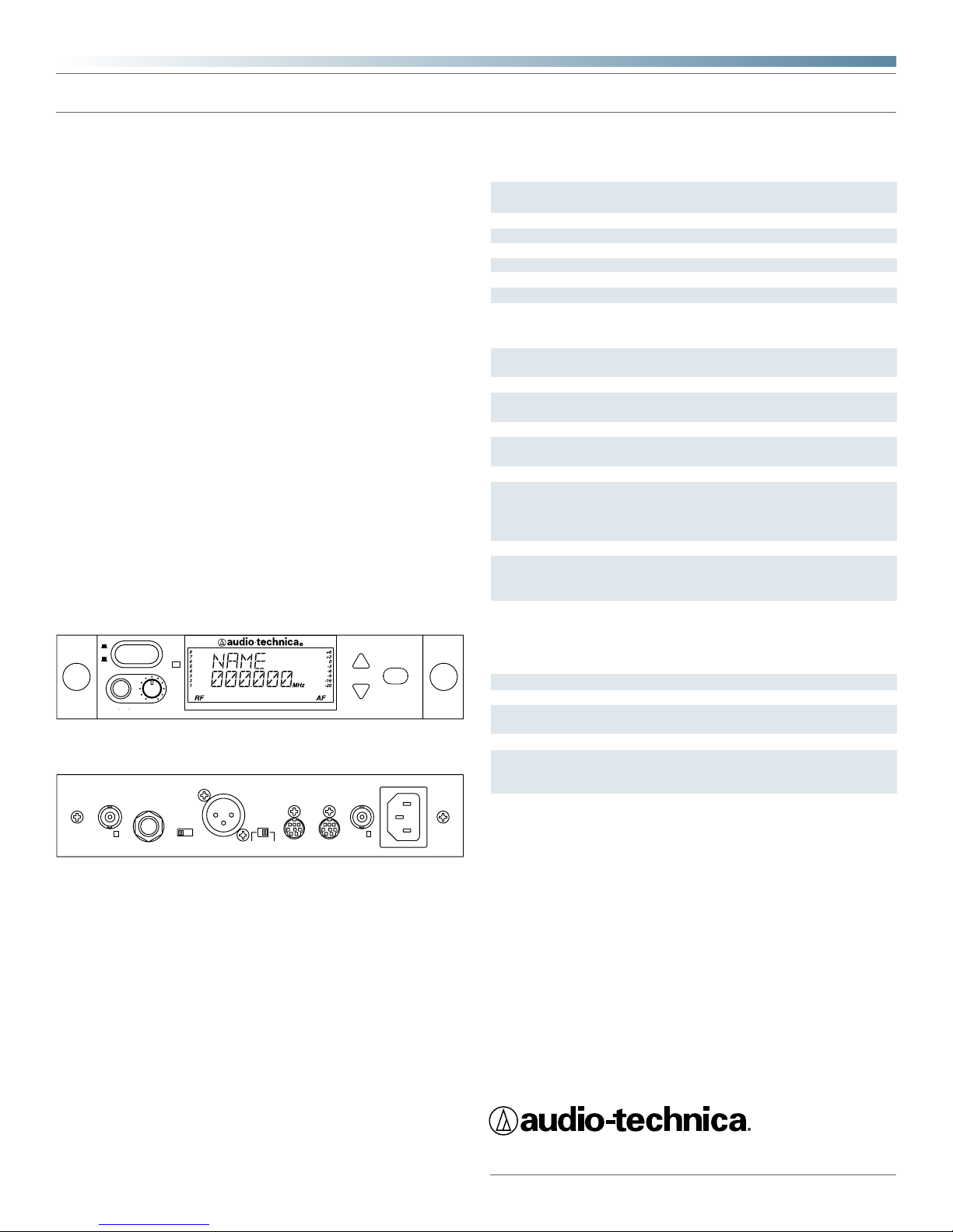
front
back
ON
OFF
ANT. B
IN
PHONES
POWER
INSTRUMENT
MIN–
LEVEL
OUTPUT
(UNBAL.)
ALERT
–MAX
UHF SYNTHESIZED DIVERSITY RECEIVER AEW-R4100
BALANCED
MIC OUTPUT
0/-6/-12
ATTN (dB)
GROUND
LIFT
GROUND IN
RX NAME
–
LINK – OUT
MODE/SET
IN
ANT. A
WARNING:
THIS APPARATUS MUST BE EARTHED.
AC
˜
100V-240V
50/60Hz
Specications
UHF operating frequencies
Number of frequencies
Frequency stability
Modulation mode
Normal deviation
Operating range
Operating temperature range
Frequency response
Receiving system
Image rejection
Signal-to-noise ratio
Total harmonic distortion
Sensitivity
Intermediate frequency
Audio output (attn switch at “0”)
Audio output attenuator (ATTN)
Output connectors
Headphone output
Antenna power
Power supply
Dimensions
Net weight
Accessories included
In the intere st of standards develo pment, A.T.U.S. offers full
details on it s test methods to othe r industry
Specications are subject to change without notice.
professionals on request.
Overall system
Band C: 541.500–566.375 MHz;
Band D: 655.500–680.375 MHz
996 total per band (25 kHz increments)
±0.005%, Phase Lock Loop frequency control
FM
±5 kHz
300' typical
5° C (41° F) to 45° C (113° F)
70 Hz to 15 kHz
AEW-R4100 receiver
Dual independent RF sections, automaticswitching diversity
60 dB typical
115 dB at 40 kHz deviation (IEC-weighted),
75 kHz maximum modulation
≤1% (10 kHz deviation at 1 kHz)
20 dBµV (S/N 70 dB at 5 kHz deviation,
IEC-weighted)
65.75 MHz, 10.7 MHz
Microphone: 25 mV (at 1 kHz, ±5 kHz deviation, 10k ohm load),
Instrument: 50 mV (at 1 kHz, ±5 kHz deviation, 10k ohm load)
Three-position switch: 0 / –6 / –12 dB
Microphone: XLRM-type, (balanced);
Instrument: 6.3 mm (
1
/4") TS unbalanced
phone jack
Connector: 6.3 mm (1/4") TRS (“stereo”)
phone jack; Power output: 10 mW + 10 mW
at 1 kHz, ±5 kHz deviation into 32 ohms;
maximum output, 220 mW + 220 mW into
32 ohms
DC 10V-12V, 20 mA (BNC-type jack)
100-240V AC 50/60 Hz, 8W
211.0 mm (8.31") W x 44.0 mm (1.74") H x
235.0 mm (9.26") D
1.7 kg (3.8 lbs) (without accessories)
Detachable IEC-type AC power cable; two
exible UHF half-wave antennas; link cable;
rack-mount adapters
Audio-Technica U.S., Inc., 1221 Commerce Drive, Stow, Ohio 44224
Audio-Technica Limited, Old Lane, Leeds LS11 8AG England
©2010 Audio-Technica U.S., Inc. audio-technica.com 0001-0017-01
 Loading...