

Page 1

Professional UHF Wire less Systems
AEW-DA550C Diversity UHF Antenna Distribution System, 540-565 MHz
AEW-DA660D Diversity UHF Antenna Distribution System, 655-680 MHz
Installation and Operation
Page 2
Prior to use of this product, review all safety markings and instructions.
POWER
ON
OFF
CCAAUUTTIIOON
SSHHOOCCK
N
C
K
N
RRIISSKK OOFF EELLEECCTTRRIIC
DDOO NNOOTT OOPPEEN
To prevent electric shock, do not remove the cover. There are no
user-serviceable parts inside. Internal adjustments are for qualified
professionals only. Refer all servicing to qualified service personnel.
Pour prévenir un choc électrique, ne pas ouvrir le couvercle. Il n’y
aucune pièces de rechanges à l’intérieur. Tout ajustement interne
doit être fait par une personne qualifié seulement. Référez tout
réparation au personnel qualifié.
Warning/Attention:
To prevent fire or shock hazard, do not
expose this appliance to rain or moisture.
Pour prévenir feu ou choc électrique, ne pas
exposé l’appareil à la pluie ou à l’humidité.
AAVVIIS
RRIISSQQUUEE DDEE CCHHOOC
S
ÉÉLLEECCTTRRIIQQUUE
NNEE PPAASS OOUUVVRRIIR
E
C
R
AEW-DA550C and AEW-DA660D Installation and Operation
The AEW-DA550C and AEW-DA660D are UHF active unity-gain
diversity antenna distribution systems. Identical in all other
respects, the AEW-DA550C operates over a nominal 540-565
MHz range, while the AEW-DA660D operates over a nominal
655-680 MHz range. These units are designed to complement
wireless systems operating in the Audio-Technica “C” Band
(541.500 - 566.375 MHz) or “D” Band (655.500 - 680.375
MHz), as well as other wireless systems operating
in the same frequency ranges.
For conciseness, only the AEW-DA550C model is mentioned
in the following instructions. All information in this manual
applies to both models, except as noted.
The AEW-DA550C provides two identical sections, one
for each antenna of a UHF diversity wireless system.
Each section in the unit comprises an antenna input, four
bandpassed, isolated receiver outputs, and a bandpassed
“cascade” directional coupler to supply signal to additional
AEW-DA550C units. All RF connectors are BNC-type. Ten
BNC-to-BNC RF interconnect cables are included with the unit.
WARNING: This apparatus must be grounded.
This product is a safety class 1 product. There must be an
uninterruptible safety earth ground from the main power
source to the product’s AC input. Whenever it is likely that
the protection has been impaired, disconnect the power cord
until the ground has been restored.
ATTENTION: Cet appareil doit être mise à la terre.
Cet appareil est de classe de sûreté 1. Il doit y avoir un
ininterrompable de mise à la terre de sécurité provenant de
la source principale de courant de l’appareil de l’entrée du
courant alternatif. Quand la protection a été affaiblie, débrancher
le fil de courant jusqu’à la mise à terre a bien été réétablie.
The detachable IEC type power input cord supplied is intended for
use in regions with mains voltage in the range of 100–125VAC
only. Use only the furnished power cord that includes the
appropriate NEMA 5-15P/ANSI C73.11 type attachment plug.
For use in geographical areas with mains voltage outside of the
range 100–125VAC, it is necessary for the user to utilize a power
cord rated and configured for operation in their region. Replace the
supplied power cord with a cord rated for correct voltage operation.
Antennas can be remotely located from the unit. However,
due to signal loss in cables at UHF frequencies, use the
lowest-loss RF cable type(s) practical for any cable runs over
25 feet. RG-8 is a good choice. Use only copper-shielded
cable, not CATV-type foil-shielded wire.
Either passive or active antennas may be used. Both antenna
input jacks offer switchable +12V DC output on their center
pins to operate Audio-Technica powered antennas or other
in-line RF devices, if desired. Up to 250 mA can be drawn
from each antenna input jack.
Additionally, four jacks on the rear panel provide 12V DC
(center positive) to power as many as four receivers operating
on 12 volts at up to 500 mA each. Included with the unit are
four DC cables appropriate for use with ATW-R310 (or likepowered) receivers.
The 12-volt supplies for powering receivers and in-line devices
are short-circuit protected.
The unit features a steel case with steel-reinforced front
panel and rear rack-mount supports for extreme durability.
An included set of RF cables and connectors permits
front-panel antenna mounting.
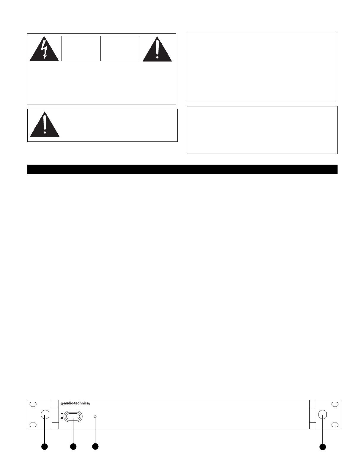
Front Panel Controls and Functions (Fig. A)
1. POWER SWITCH: Press switch to apply AC power to unit. Press again to turn unit off.
2. POWER INDICATOR: Shortly after power is applied, the indicator will light.
3. FRONT-MOUNT ANTENNAS: Cables and panel connectors are included to permit attaching antennas at the front panel.
Figure A Front Panel
2
3
1
2
3
Page 3

Power Connections
The switching power supply is designed to operate properly
from any AC power source 100–240V, 50/60 Hz without user
adjustment. Simply connect the receiver to a standard AC
ower outlet, using only an IEC 320-type input cordset
p
approved for the country of use. Power to the unit is
controlled by the front-panel Power switch.
An auxiliary AC “jumper” (pass-through) outlet is provided
on the rear panel, and a ”jumper” power cordset is included,
to simplify power connections by “daisy-chaining” together
an array of AEW receivers and antenna distribution units.
Maximum output from the auxiliary AC outlet is 500 watts;
it is fused internally. Do not exceed the 500W power limit.
o not connect high-current devices, such as power
D
amplifiers, to this outlet.
Rear Panel Controls and Functions (Fig. B)
4. CHANNEL “B” ANTENNA INPUT: Attach the “B” antenna here, or extend it with a low-loss antenna cable. (Antenna and
cable not included.) The antenna input jack also is capable of providing +12V DC output on its center pin at up to 250 mA to
power in-line RF devices.
5. CHANNEL “B” ANTENNA POWER SWITCH: Enables or disables +12V DC on the Channel “B” Antenna Input connector
(#4).
6. CHANNEL “B” CASCADE OUTPUT: Directional coupler provides RF output to additional distribution systems operating in
the same frequency band. Each cascade output should be connected to only one other unit’s input, and no more than three
distribution units total should be “daisy-chained.”
Front-mount Antennas
NC-to-BNC connectors and jumper cables are included with
B
the unit to permit mounting antennas on the front panel.
• BNC-BNC through-panel connectors: Remove the nut and
lock-washer from each connector. Install the connectors
from the front into the two panel holes. Note that the flat
on the threaded section must be aligned with the flat in
each panel hole. Secure each connector from the back
with its lock-washer and nut, tightening the nut firmly.
• BNC-BNC cable jumpers: Connect the jumpers to the
rear antenna jacks first; then attach them to the BNC
connectors on the front panel. Make certain the bayonet
twist-rings are fully latched on the connectors at both
ends.
7. CHANNEL “B” DISTRIBUTION OUTPUTS: Four jacks provide RF distribution to receivers operating in the same frequency
band. Each output should be connected to only one other antenna input, without “daisy-chaining.” Unused outputs do not
require termination.
8. CHANNEL “A” ANTENNA INPUT: See #4 above.
9. CHANNEL “A” ANTENNA POWER SWITCH: Enables or disables +12V DC on the Channel “A” Antenna Input connector
(#8).
10. CHANNEL “A” CASCADE OUTPUT: See #6.
11. CHANNEL “A” DISTRIBUTION OUTPUTS: See #7.
12. DC OUTPUT JACKS: Provides 12V DC (center positive) at up to 500 mA from each jack to power receivers. Connect the
included ATW-RDCN cables here to supply 12V DC to up to four ATW-R310 (or like-powered) receivers.
13. AUXILIARY AC OUTLET: An auxiliary AC pass-through outlet and included IEC “jumper” power cordset simplify making
power connections to an array of AEW receivers and antenna distribution units. Maximum output from the auxiliary AC
outlet is 500 watts; it is internally fuse-protected.
14. AC POWER INPUT: IEC-type connector for 100V–240V AC, 50/60 Hz power input. No adjustment for mains voltage/
frequency is necessary.
15. REAR RACK MOUNT: Mounts are provided at the rear of the side panels to permit attachment to rear rack rails in racks so
equipped.
Figure B Rear Panel
15 4
14
6
7 12 155
8 119
10
13
3
Page 4

Nominal Frequency Range
AEW-DA550C 540-565 MHz
AEW-DA660D 655-680 MHz
Nominal Amplifier Gain 0 dB, ±3 dB
Nominal Cascade Gain –3 dB, ±3 dB
Input Impedance 50 ohms
Output Impedance 50 ohms
In-line Antenna Power +12V DC on RF input jacks,
250 mA maximum per jack
External Receiver Power 12V DC, center positive,
500 mA maximum per jack (4 total)
Extensive information about using wireless systems and accessories is available on the Audio-Technica Web site at
Specifications
Power Input 100-240V AC, 50/60 Hz, auto-adjusting,
500W maximum. (Includes AC
pass-through load.)
Dimensions 19.00" (480.0 mm) W x 1.92" (48.8 mm)
H x 11.00" (280.0 mm) D
Weight 5.9 lbs (2.7 kg)
Accessories Included IEC 320-type 120V power cordset;
IEC 320-type AC pass-through cable;
10 BNC-to-BNC 1.5' RF interconnect
cables; front-mount antenna cables and
connectors; 4 ATW-RDCN DC power
interconnect cables; 4 plastic feet with
screws.
www.audio-technica.com
To reduce the environmental impact of a multi-language printed document, product
information is available online at www.audio-technica.com in a selection of languages.
Afin de réduire l’impact sur l’environnement de l’impression de plusieurs, les informations
concernant les produits sont disponibles sur le site www.audio-technica.com dans une large
sélection de langue.
Para reducir el impacto al medioambiente, y reducir la producción de documentos en varios
leguajes, información de nuestros productos están disponibles en nuestra página del
Internet: www.audio-technica.com.
Para reduzir o impacto ecológico de um documento impresso de várias linguas, a
Audio-Technica providência as informações dos seus produtos em diversas linguas na
www.audio-technica.com.
Per evitare l’impatto ambientale che la stampa di questo documento determinerebbe, le
informazioni sui prodotti sono disponibili online in diverse lingue sul sito
www.audio-technica.com.
Der Umwelt zuliebe finden Sie die Produktinformationen in deutscher Sprache und weiteren
Sprachen auf unserer Homepage: www.audio-technica.com.
Om de gevolgen van een gedrukte meertalige handleiding op het milieu te verkleinen, is
productinformatie in verschillende talen “on-line” beschikbaar op: www.audio-technica.com.
Audio-Technica U.S., Inc., 12 21 Commerce Drive, Stow, Ohio 44224 330/686-2600
Audio-Technica Limited, Old Lane, Leeds LS11 8AG England (0)113 277 144 1
P51621-01 ©2011 Audio-Technica U.S., Inc. Printed in U.S.A.
 Loading...