

Page 1

High-Performance
Car- amplifier
designed and engineered by audio system Germany
owner‘s manual
X 75. 4 D
X 120.2 D
the sound
R
since 1988
Page 2

X 120.2 D
X 75.4 d.
Congratulation on your purchase of your new X Series amlifier.
- 2-Channel High-Power Full-Range Digital amplifier
- Stable into 2 ohm stereo per channel and 4 ohm bridged mode
- Variable switchable Low Pass Filter from 50 to 300 Hz
- Variable switchable High Pass Filter from 25 to 175 Hz
- Input Sensitivity: variable 200 mV maximum to 8 V minimum
- Multi-Way Protection Circuitry: overheating, overcurrent, short circuitry and
speaker DC protection
- Operating Voltage : DC 10 ~ 16 V power input
- Wired Remote Control RTC (optional)
- High-Power-Input (normally originial radio) with automatically „Turn-On“
- Adaptercable HLAC and rca hi (optional)
- 4-Channel High-Power Full-Range Digital amplifier
- Stable into 2 ohm stereo per channel and 4 ohm bridged mode
- Variable switchable Low Pass Filter from 50 to 3500 Hz
- Variable switchable High Pass Filter from 50 to 3500 Hz
- Input Sensitivity: variable 200 mV maximum to 8 V minimum
- Multi-Way Protection Circuitry: overheating, overcurrent, short circuitry and
speaker DC protection
- Operating Voltage : DC 10 ~ 16 V power input
- Wired Remote Control RTC (optional)
- High-Power-Input (normally originial radio) with automatically „Turn-On“
- Adaptercable HLAC and rca hi (optional)
IMPORTANT: Before installation your power amplifier, we recommend to read the
ownder´s manual carefully and to follow the instructions regarding connection and
fitting exactly.
ATTENTION: Pay attention to advices and instructions of the car manufacturer.
IMPORTAN: Ihr Kaufbeleg dient als Garantienachweis für etwaige Reparaturen
oder Austausch. Bewahren Sie Ihren Kaufbeleg, Bedienungsanleitung und
Originalver-packung auf.
ATTENTION: Use of sound components can impair your ability to hear necessary
traffic sounds and may constitute a hazard while driving your automobile.
Audio SystemGermany accepts no liability for hearing loss, bodily injury or
property damage as a result of use or misuse of our products.
We recommend installing the equipment by an authorized service center or dealer. A
professional fitting and connection is the requirement for further warranty and perfect
sound.
features
2
Page 3
X 120.2 D / X 75.4 D.
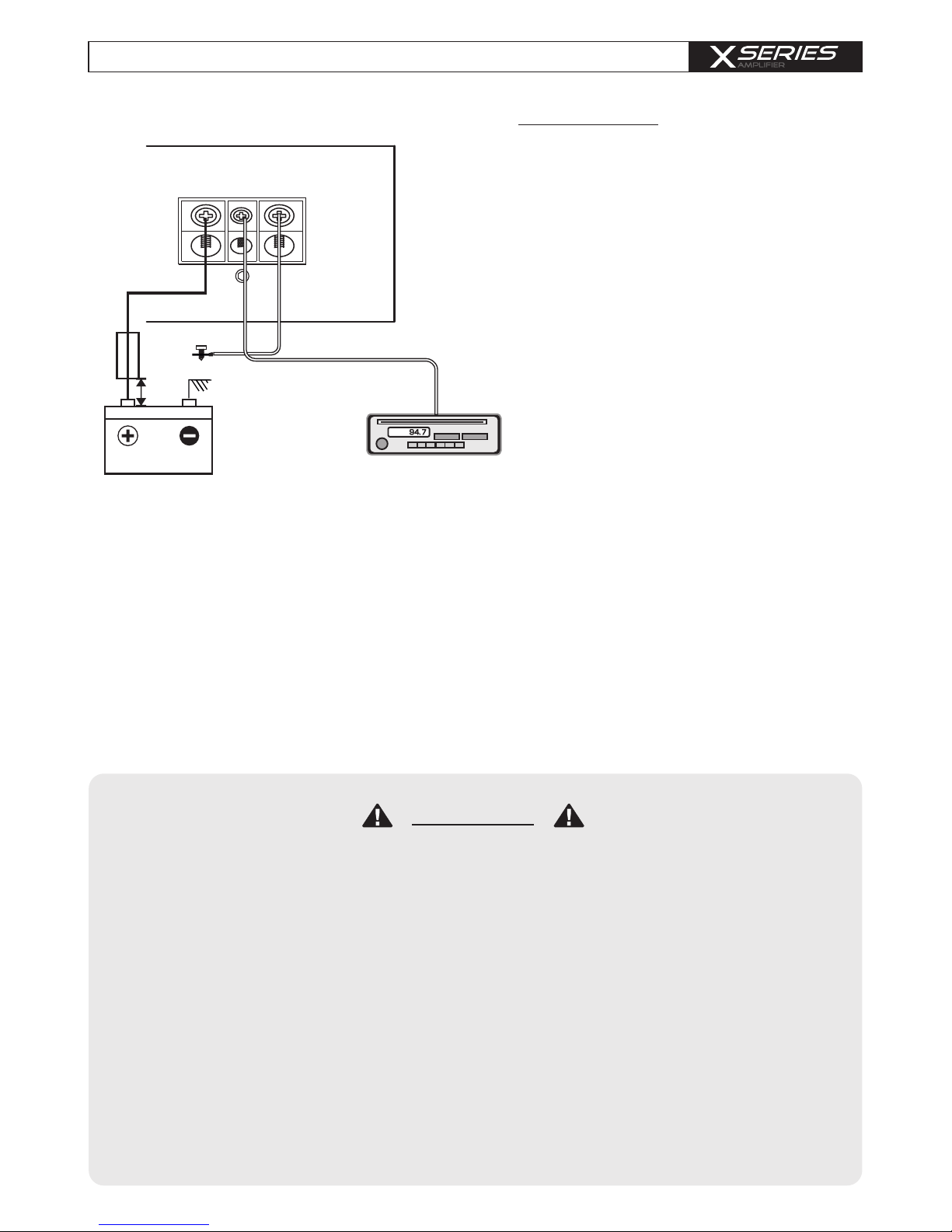
3. +12 V Power connection
Connect the +12 V contact of the amplifier with the supply cable via a fuse directly to the
vehicle battery. Keep in mind, that the length of the cable from fuseholder to vehicle battery
has to be a maximum of 30 cm.
Requirement for a perfect function of the amplifier is a qualitative high end fuse holder as well
as a suitable cable cross section (AWG sice 8 - 6). This fuse protects the amplifier and the
vehicle against the possibility of a short circuit in the power cable.
4. Remote connection
Connect the REM-terminal of the amplifier to the remote-output (automatic 12 V antennaoutput) of the head unit. Therefore use a 0,5 - 1,5 mm power cable.
a) Take care of a professional attachement. Pay attention, that no electrical cable, gas
tank, hydraulic breakes or other components get damaged.
b) There has to be enough cooling and air circulation. Avoid the installation in small
closed boxes or close to heatening parts.
c) Protect the amplifier from fluids, wetness, heat and foreign material as well as from
other influences.
d) The amplifier is only to be built into vehicles with a 12 V DC power supply.
e) Never install the power supply cable with other original wires of the vehicle
(gas cables), fan motors, brand control moduls etc.
f) Install the signal cable (cinch cable) as well as the speaker cable far away of the
power cables to avoid troubles with the music signal.
g) The cables of your amplifier have to be installed, so that there is no danger of binding,
squeezing or breaking.
+12V
REM
GND
BATTERY
GROUND
ATTENTION:
1. Battery disconnection
First disconnect the power supply of the
vehicle. This works out the best by
removing the ground cable of the battery.
2. Ground connection
Connect the GND (ground) connection of
the amplifier with the car chassis. Keep
this cable as short as possible (not longer
than 50 cm) and use a suitable cross
section (AWG sice 8 - 6).
Make sure, that the connection with the
vehicle chassis is free of paint, dirt and
dust.
remote connection
HEAD UNIT
fuse
Max .
30 cm
3
POWER CONNECTIOn
Please follow the instructions during the installation of your amplifier:
Achtung
Page 4

X 120.2 D
The X Series amplifier offers RCA-Inputs, which are connected through cinch cables with
the preamplifier-outputs of the head unit. If the head unit (OEM-RADIO) has no RCA-Output,
than it is possible to connect the speaker output direct to RCA/Cinch-Input. Important: the
Gain-Controller has to be adjusted to minimum, then carfully turn up the volume. Input Mode
has to be switched on „HI“. If signal is presented, the amplifier automacally turns on.
Adaptercable HLAC and RCA HI can be purchased at your specialized dealer. The RCAoutputs provide the possibility to transfer the signal of the head unit to a 2. amplifier via a cinch
cable (not possible for x 75. 4 D).
With the aid of the shiftable high- and lowpassfilter, the gain-controller and the bassbost you
are able to adjust the amplifier on to your prefered taste of hearing, the circumstances of the
vehicle and to the speakers.
In this regard, AUDIO SYSTEM germany recommends to adjust your amplifier
through a specialized service center, dealer or a specialist.
X 75.4 D.
RCA connection
HEAD U NI T
HEAD U NI T
4
Wired Remote Control
RTC (optional)
Wired Remote Control
RTC (optional)
for channel 3 + 4
to INP UT of
addi tiona l
AMPL IFIER S
the sound
R
since 1988
the sound
R
since 1988
Page 5

X 120.2 D
1-Channel Bridged
Tri-Mode
2-Channel Stereo
speaker
impedance
4 ~ 8 Ohm
speaker
impedance
2 ~ 8 Ohm
speaker
impedance
4 ~ 8 Ohm
speaker connection
CH 1
CH 1
CH 2
CH 2
coil
5
the sound
R
since 1988
the sound
R
since 1988
the sound
R
since 1988
Page 6

X 75.4 D.
speaker connection
2-Channel Mono
2-Channel Stereo + 1-Channel Mono Bridged
4-Channel Stereo
6
CH 1
CH 1
CH 1/2 CH 3/4
CH 3/4
CH 3
CH 2
CH 2 CH 4
speaker
impedance
4 ~ 8 Ohm
speaker
impedance
2 ~ 8 Ohm
speaker
impedance
4 ~ 8 Ohm
Page 7

This power amplifier is featured with a efficient protection system to prevent any damages
like over-heating, overvoltage, short-circuit and DC at the loudspeaker output.
Occuring an error the protection-LED will light in red.
In order to check the problem, first turn down all levels of the head unit, afterwards turn it
off.
AMPLIFIER IS NOT
POWERED UP, NO
LED IS LIGHTENING
- ground connection professional connected?
- +12V powercable professional connected?
- remote cable professional connected?
- fuses inserted and alright?
- analyze voltage on the amplifier.
PROTECTION LED
ILLUMINATES GREEN
WHILE AMPLIFIER IS
SOUNDLESS
- cinch cable alright and professional connected?
- loudspeaker professional connected?
- head unit alright?
PROTECTION LED
ILLUMINATES RED
WHEN AMPLIFIER IS
POWERED UP
- amplifier too hot?
- short-circuit at the loudspeaker output?
- short-circuit caused by loudspeaker cable with vehicle
chassis (ground)?
- input voltage too high (e.g.faulty lighting dynamo)?
ERROR IN
AMPLIFIER FUSE
- ground professional connected?
- loudspeaker impedance alright?
! CAUTION !
Make sure when changing fuses to use the same value.
SOUND TOO LOW
OR
LOW-DISTORTED
SOUND
- input level control “GAIN” is set to match the head unit?
- output level control of the head unit alright?
- loudspeaker error?
- loudspeaker cable checked?
- crossover frequencies has been properly set?
(Check head unit, amplilfier, DSP, soundprozessor,
equalizer,
HIGH HISS-ENGINE
NOISE IN SPEAKERS
- ground connection professional connected?
- short-circuit caused by loudspeaker cable with vehicle
chassi (ground)?
- cinchcable (RCA) and/or loudspeaker cabel installed too
close to the power connection cable?
- cinch ground (RCA) of the head unit alright?
Please contact your specialist dealer if the amplifier is still not working after it has
been checked with the error list!
For warranty adjustement / repairs the original invoice has to be attached!
Opening the power amplifier is leading to a lost of warranty in either case!
ATTENTION
OVERHEATING
(PROTECTION LED
ILLUMINATES RED WHEN
AMPLIFIER IS POWERED
UP)
- impedance alright?
- loudspeaker error?
- adequate airflow of the amplifier?
! CAUTION !
After cooling down, the amplifier turns on
TROUBLE SHOOTING
7
Page 8

X 120.2 D
10 - 16 V
4x 75 W
4x 125 W
2x 250 W
>96 dB
50 ~ 3500 Hz
25 ~ 3500 Hz
10 Hz ~ 50 KHz (+/-1 dB)
< 0,031%
75 dB
40 A x 1
200 mV ~ 8 V (+/- 5%)
150(W) x 47(H) x 170(L) mm
Power Supply Voltage
Rated Power Output at 14,4 V
-RMS power @ 4 ohm stereo
-RMS power @ 2 ohm stereo
-RMS power @ 4 ohm bridged
Signal to Noise Ratio
Low Pass Crossover
High Pass Crossover / Subsonic filter
Frequency Response
THD@RMS Watts
Channel Separation
Fuse Rating
Input Sensitivity
Dimensions
10 - 16 V
2x 120 W
2x 200 W
1x 400 W
>96 dB
50 ~ 300 Hz
25 ~ 175 Hz
10 Hz ~ 50 KHz (+/-1 dB)
< 0,028%
75 dB
40 A x 1
200 mV ~ 8 V (+/- 5%)
150(W) x 47(H) x 170(L) mm
X 75.4 D.
--------------------------------------------------------------
----------------------------------------
----------------------------------------
-------------------------------------
-----------------------------------------------------------
----------------------------------------------------------------------
---------------------------------------------
---------------------------------------------------------
-------------------------------
-------------------------------------------------------------------
-------------------------------------------------------------------------
------------------------------------------------------
-----------------------------------------------------------------------
Power Supply Voltage
Rated Power Output at 14,4 V
-RMS power @ 4 ohm stereo
-RMS power @ 2 ohm stereo
-RMS power @ 4 ohm bridged
Signal to Noise Ratio
Low Pass Crossover
High Pass Crossover / Subsonic Filter
Frequency Response
THD@RMS Watts
Channel Separation
Fuse Rating
Input Sensitivity
Dimensions
--------------------------------------------------------------
----------------------------------------
----------------------------------------
------------------------------------
-----------------------------------------------------------
----------------------------------------------------------------------
---------------------------------------------
--------------------------------------------------------
-------------------------------
-------------------------------------------------------------------
-------------------------------------------------------------------------
------------------------------------------------------
-----------------------------------------------------------------------
SPECIFICATIONS
8
 Loading...