

Page 1

X 100.2
X 70.4
X 75.6
designed and engineered by audio system Germany
High-Performance
Car- amplifier
owner‘s manual
Page 2
features
-2-
2-Channel High Power Class-AB amplifier with SMD technology
Full MOS-FET Power amplifier
Stable into 2 ohm stereo per channel and 4 ohm bridged mode
Variable switchable Low Pass Filter from 50 to 300 Hz
Variable switchable High Pass Filter from 25 to 175 Hz
Variable switchable Band Pass Filter from 25 to 175 Hz and from 50 to 300 Hz (LPF)
High-Level-Input with automatically „TURN ON“
Input Sensitivity: variable 200 mV maximum to 8 V minimum
Multi-Way Protection Circuitry: overhead, over current, short circuitry and speaker DC protection
Operating Voltage: DC 10 ~ 16 V Power Input
Massive heavy aluminum-heatsink with fan cooling on top
Wired Remote Controller RTC (Optional)
FSA Front Stage adjuster for analog phase correction for the left front channel
X 100.2
6-Channel Full MOS-FET High Power Class-AB amplifier with SMD technology
Phaseshift from 0-180° (channel 5+6)
Stable into 2 ohm stereo per channel and 4 ohm bridged mode
Variable switchable Low Pass Filter from 50 to 300 Hz (channel 5 + 6)
Variable switchable High Pass Filter from 20 to 6000 Hz (channel 1 + 2)
Variable switchable filter (channel 3 + 4) from 25 to 200 Hz (HP) and from 50 to 5000 Hz (LP)
High-Level-Input with automatically „TURN ON“
Input Sensitivity: variable 200 mV maximum to 8 V minimum
Multi-Way Protection Circuitry: overhead, over current, short circuitry and speaker DC protection
Operating Voltage: DC 10 ~ 16 V Power Input
Massive heavy aluminum-heatsink with fan cooling on top
Wired Remote Controller RTC (Optional)
FSA Front Stage adjuster for analog phase correction for the left front channel
X 75.6
4-Channel High Power Class-AB amplifier with SMD technology
Full MOS-FET Power amplifier
Stable into 2 ohm stereo per channel and 4 ohm bridged mode
Variable switchable Low Pass Filter from 50 to 300 Hz (channel 3 + 4)
Variable switchable High Pass Filter from 20 to 6000 Hz (channel 1 + 2)
Variable switchable Band Pass Filter (channel 3 + 4) from 20 to 200 Hz (HP)
and from 50 to 5000 Hz (LP)
High-Level-Input with automatically „TURN ON“
2- or 4-channel mode switchable
Input Sensitivity: variable 200 mV maximum to 8 V minimum
Multi-Way Protection Circuitry: overhead, over current, short circuitry and speaker DC protection
Operating Voltage: DC 10 ~ 16 V Power Input
Massive heavy aluminum-heatsink with fan cooling on top
FSA Front Stage adjuster for analog phase correction for the left front channel
X 70.4.
Congratulations on your purchase of your new
xseries amplifier.
Before installation your power amplifier, we recommend to read the
manual's owner carefully and to follow the instructions regarding connection and
fitting exactly.
We advice to accomplish the installation by an authorized service center, because
a professional fitting and connection is the requirement for further warranty
adjustments.
Page 3
GND
REM
+12V
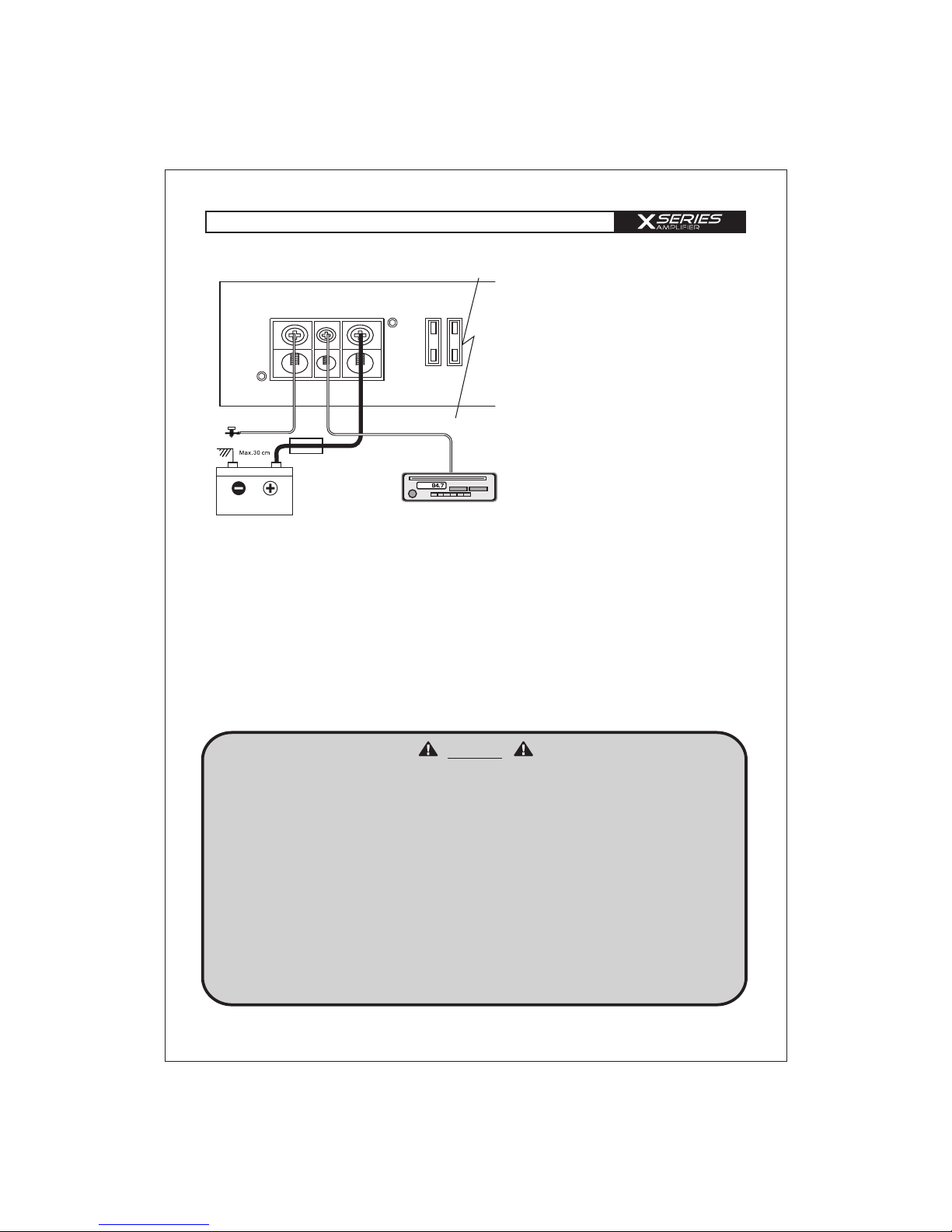
X 100.2 / X 75.6 / X 70.4 .
Powe r CO NNECTI O N
-3 -
3. +12 V Power connection
Connect the +12 V contact of the amplifier with the supply cable via a fuse directly to the vehicle
battery. Keep in mind, that the length of the cable from fuseholder to vehicle battery has to be
maximum 30cm. For the amplifier to function at its best, use a high quality fuse holder and suitable
cable preferably AWG 5 - 3 cable. This fuse protects the amplifier and the vehicle against the possibility
of a short circuit in the power cable.
4. Remote connection
Connect the REM-terminal of the amplifier to the remote-output (automatic 12 V antenna-output) of
the head unit. Use a 0,5 - 1,5 mm² power cable.
5. HI/LOW selectable button
If the radio (normally original radio) has no RCA output and remote output (automatic 12 V antenna
output) it is possible to connect the speaker output from headunit direct in RCA input. The HI/LOW
button must be switched to „HI“ (picture on page 4). If the X SERIES amplifier get a signal from
head unit output, the amplifier will turn on.
1. Battery disconnection
First, disconnect the power supply of the
vehicle by removing the ground cable of
the battery.
2. Ground connection
Connect the GND (ground) connection
of the amplifier with the car chassis.
Keep this cable as short as possible (not
longer than 50 cm) and use a suitable
cross section (AWG size 5 - 3).
Make sure, that the connection with the
vehicle chassis is free of paint, dirt and
dust.
BATTERIE
MASSE
Sicherung
Remote Anschluss
Steuergerät (Radio)
a) Take extra care when making the connections. Make sure that no electrical cable, gas tank,
hydraulic brakes or other components get damaged.
b) Allow enough cooling and air circulation and avoid installing the unit in small closed boxes
or close to parts that heats up easily.
c) Keep the amplifier away from liquid, moisture, heat and foreign materials.
d) This amplifier can only be used in vehicles with 12V DC power supply.
e) Never install the power supply cable with other original vehicle wires (gas cables), fan motors,
control modules etc.
f) Install the signal cable (cinch cable) as well as speaker cable far away from the power cables
to avoid interference with music signals.
g) To avoid dangers of cables binding, squeezing or breaking, use the cables supplied with
your amplifier.
Please take the following precautions when installing your amplifier:
Caution
Page 4

-4 -
RCA con n ection
X 75.6 (channel 5 + 6)
HEAD UNIT
Wired Remote
Control RTC
(optional)
HEAD UNIT HEAD UNIT
X 70.4 / X 75.6 . (channel 1 - 4)
RCA INPUT
mode
4 CH / 6 CH
RCA INPUT
mode
4 CH / 6 CH
The x series amplifier offers RCA-Inputs, which are connected through cinch cables with the
preamplifier-outputs of the head unit.
With the aid of the variable high- and lowpassfilter and the gain-controller you are able to adjust the
amplifier on to your prefered taste of hearing, the circumstances of the vehicle and to the speakers.
Another special feature is the FSA (Front Stage Adjuster). Ths is a analog phase correction for the left
front channel. By adjusting the FSA volume you can set the sound and voices in front of you.
In this regard, AUDIO SYSTEM Germany recommends to adjust your amplifier through a
specialized service center, dealer or a specialist.
Optional the x 75.6 und X 100.2 can be installed to a wire remote controller RTC, which allows you
to rule the amplifier in front of the car (only if the LPF is switched „ON“).
.
FSA
volume
FSA on/off
switch
FSA on/off
switch
HI / LOW
switch
HI / LOW
switch
LPF
on/off
1x o. 20x
switch
LPF
switch
on/off
LPF
switch
on/off
HPF
switch
on/off
Variable
phase-shift
HP
filter
1x o. 40x
X 100.2
HP
filter
FSA
volume
Page 5

spe a ker conn e ction
-5 -
1-Channel Bridged
2-Channel Stereo
Tri-Mode
Speaker
Impedance
4 ~ 8 ohm
Speaker
Impedance
2 ~ 8 ohm
Speaker
Impedance
4 ~ 8 ohm
X 100.2 / X 75.6 (channel 5 + 6)
Protection
Power
REMOTE
+ BRIDGE -
CH1/L CH2/R
ON
OFF
HERTZ
50 300
LPF
90 225
Protection
Power
REMOTE
+ BRIDGE -
CH1/L CH2/R
ON
OFF
HERTZ
50 300
LPF
90 225
Protection
Power
REMOTE
+ BRIDGE -
CH1/L CH2/R
ON
OFF
HERTZ
50 300
LPF
90 225
coil
Page 6

+ BRIDGE -
+ BRIDGE -
CH1/L CH2/R
CH3/L
CH4/R
Protection
Power
Channel 3 / 4
Channel 1 / 2
LPF
LPF
HERTZ
HERTZ
5050300
300
ON
ON
OFF
OFF
9090225
225
HPF
HPF
2525175
175
HERTZ
HERTZ
ON
ON
OFF
OFF
40
40
120
120
REMOTE
+ BRIDGE -
+ BRIDGE -
CH1/L CH2/R
CH3/L
CH4/R
Protection
Power
Channel 3 / 4
Channel 1 / 2
LPF
LPF
HERTZ
HERTZ
5050300
300
ON
ON
OFF
OFF
9090225
225
HPF
HPF
2525175
175
HERTZ
HERTZ
ON
ON
OFF
OFF
40
40
120
120
REMOTE
+ BRIDGE -
+ BRIDGE -
CH1/L CH2/R
CH3/L
CH4/R
Protection
Power
Channel 3 / 4
Channel 1 / 2
LPF
LPF
HERTZ
HERTZ
5050300
300
ON
ON
OFF
OFF
9090225
225
HPF
HPF
2525175
175
HERTZ
HERTZ
ON
ON
OFF
OFF
40
40
120
120
REMOTE
-6 -
2-Channel Bridged
4-Channel Stereo
2-Channel Stereo + 1-Channel Mono Bridged
X 70.4 / . X 75.6 (channel 1 + 2 und 3 + 4)
CH1/2-MONO
Speaker
Impedance
4 ~ 8 ohm
Speaker
Impedance
2 ~ 8 ohm
CH2
CH1
CH3
CH4
Speaker
Impedance
4 ~ 8 ohm
CH3/4-MONO
CH3/4-MONO
CH2
CH1
spe a ker conn e ction
Page 7

trou b le shooti n g
-7-
This power amplifier is featured with a efficient protection system to prevent any damages like
over-heating, overvoltage, short-circuit and DC at the loudspeaker output.
Occuring an error the protection-LED will light in red.
In order to check the problem, first turn down all levels of the head unit, afterwards turn it off.
AMPLIFIER IS NOT
POWERED UP, NO LED
IS LIGHTENING
- ground connection professional connected?
- +12V powercable professional connected?
- remote cable professional connected?
- fuses inserted and alright?
- analyze voltage on the amplifier.
PROTECTION LED
ILLUMINATES GREEN
WHILE AMPLIFIER IS
SOUNDLESS
- cinch cable alright and professional connected?
- loudspeaker professional connected?
- head unit all right?
PROTECTION LED
ILLUMINATES RED
WHEN AMPLIFIER IS
POWERED UP
- amplifier too hot?
- short-circuit at the loudspeaker output?
- short-circuit caused by loudspeaker cable with vehicle
chassis (ground)?
- input voltage too high (e.g.faulty lighting dynamo)?
ERROR IN AMPLIFIER
FUSE
- ground professional connected?
- loudspeaker impedance alright?
! CAUTION !
Make sure when changing fuses to use the same value
SOUND TOO LOW OR
LOW-DISTORTED SOUND
- input level control “GAIN” is set to match the head unit?
- output level control of the head unit alright?
- loudspeaker error?
- loudspeaker cable checked?
- crossover frequencies has been properly set?
(Check head unit, amplilfier, DSP, soundprozessor,
equalizer, frequency bandpassfilter...)
HIGH HISS-ENGINE NOISE
IN SPEAKERS
- ground connection professional connected?
- short-circuit caused by loudspeaker cable with vehicle
chassi (ground)?
- cinchcable (RCA) and/or loudspeaker cabel installed too
close to the power connection cable?
- cinch ground (RCA) of the head unit alright?
Please contact your specialist dealer if the amplifier is still not working after it has been
checked with the error list!
For warranty adjustement / repairs the original invoice has to be attached!
Opening the power amplifier is leading to a lost of warranty in either case!
CAUTION
OVERHEATING
(PROTECTION LED
ILLUMINATES RED WHEN
AMPLIFIER IS POWERED UP)
- impedance alright?
- loudspeaker error?
- adequate airflow of the amplifier?
! CAUTION !
After cooling down, the amplifier turns on automatically.
Page 8

specifications
10 -16 V
2x 100 W
2x 190 W
2x 250 W
1x 380 W
1x 500 W
>90 dB
50 Hz ~ 300 Hz
25 Hz ~ 175 Hz
10 Hz ~ 50 KHz (+/-1dB)
< 0.02%
75 dB
2 x 30 A
200 mV ~ 8V (+/- 5%)
258(W) x 58(H) x 185(L)mm
10 - 16 V
4x 75 W + 2x 100 W
4x 90 W + 2x 190 W
2x 180 W + 1x 380 W
>90 dB
50 Hz ~ 5000 Hz
25 Hz ~ 6000 Hz
10 Hz ~ 50 KHz (+/-1dB)
< 0.02%
75 dB
3
200 mV ~ 8 V (+/- 5%)
447(W) x 58(H) x 185(L)mm
x 30 A
10 -16 V
4x 70 W
4x 90 W
2x 180 W
> 90 dB
50 Hz ~ 5000 Hz
20 Hz ~ 6000 Hz
10 Hz ~ 40 KHz (+/-1dB)
< 0.02%
75 dB
1x 40 A
200 mV ~ 8 V (+/- 5%)
258(W) x 58(H) x 185(L)mm
Power Supply Voltage
Rated Power Output at 14,4 V
-RMS power @ 4 ohm stereo
-RMS power @ 2 ohm stereo
-RMS power @ 1 ohm stereo
-RMS power @ 4 ohm bridged
-RMS power @ 2 ohm bridged
Signal to Noise Ratio
Low Pass Crossover
High Pass Crossover / Subsonic filter
Frequency Response
THD@RMS Watts
Channel Separation
Fuse Rating
Input Sensitivity
Dimensions
X 100.2
X 70.4 .
X 75.6
-8 -
Power Supply Voltage
Rated Power Output at 14,4 V
-RMS power @ 4 ohm stereo
-RMS power @ 2 ohm stereo
-RMS power @ 4 ohm bridged
Signal to Noise Ratio
Low Pass Crossover
High Pass Crossover / Subsonic filter
Frequency Response
THD@RMS Watts
Channel Separation
Fuse Rating
Input Sensitivity
Dimensions
 Loading...