

Page 1

Owner's manual
High-END
amplifier
HX 360.2
HX 80..4
po we re d by
Audio System Germany
Fal ltorstr. 6 - 7 6707 Ha mbrücken
Page 2
Congratulations on your purchase of your new
Hxseries amplifier.
features
Before installation your power amplifier, we recommend to read the
manual's owner carefully and to follow the instructions regarding connection and
fitting exactly.
We advice to accomplish the installation by an authorized service center, because
a professional fitting and connection is the requirement for further warranty
adjustements.
-2-
HX 3 60.2
2-Channel High Power Class-AB amplifier with SMD technology
Full MOS-FET Power amplifier
Stable into 1 ohm stereo per channel and 2 ohm bridged mode
Variable switchable Low Pass Filter from 50 to 300 Hz with on/off button
Variable switchable High Pass Filter from 25 to 175 Hz with on/off button
Variable Band Pass Filter from 25 to 300 Hz
Variable Phase Shift Filter from 0 to 360 degrees
Stereo / Mono select switchable button
12dB / 24dB Slope select switchable button
Input Sensitivity: variable 200 mV maximum to 8 V minimum
Multi-Way Protection Circuitry: overhead, over current, short circuitry and speaker DC protection
Operating Voltage: DC 10 ~ 16 V Power Input
Massive heavy aluminum-heatsink with fan cooling
Wired Remote Controller RTC HX (Optional)
DIRECT INPUT controlling
HX CARD ports for individual crossover
Automatically „TURN-ON“ with High Level Input
HX 80..4
4-Channel High Power Class-AB amplifier with SMD technology
Full MOS-FET Power amplifier
Stable into 1 ohm stereo per channel and 2 ohm bridged mode
Variable switchable Low Pass Filter from 50 to 300 Hz with on/off button (Input-A)
Variable switchable High Pass Filter from 35 to 175 Hz with on/off button and the possibility
to multiply the frequency 40 times for High Pass Filterfrom 1400 to 7000 Hz (Tweeter)
Variable switchable Low Pass Filter from 50 to 300 Hz with on/off button and the possibility
to multiply the frequency 20 times for Low Pass from 1000 to 6000 Hz (Midrange)
Variable switchable High Pass Filter from 35 to 250 Hz with on/off button (Input-B)
LPF / HPF select switchable button
Variable Phase Shift Filter from 0 to 360 degrees
Stereo / Mono select switchable button
12dB / 24dB Slope selectable button
2 IN / 4 IN selectable button
Input Sensitivity: variable 200 mV maximum to 8 V minimum
Multi-Way Protection Circuitry: overhead, over current, short circuitry and speaker DC protection
Operating Voltage: DC 10 ~ 16 V Power Input
Massive heavy aluminum-heatsink with fan cooling
Wired Remote Controller RTC HX (Optional)
DIRECT INPUT controlling
Automatically „TURN-ON“ with High Level Input
Page 3
Please follow the instructions during the installation of your amplifier:
a) Take care of a professional attachement. Pay attention, that no electrical cable, gas tank, hydraulic breakes or
other components get damaged.
b) There has to be enough cooling and air circulation. Avoid the installation in small closed boxes or close to
heatening parts.
c) Protect the amplifier from fluids, wetness, heat and foreign material as well as from other influences.
d) The amplifier is only to be built into vehicles with a 12 V DC power supply.
e) Never install the power supply cable with other original wires of the vehicle (gas cables), fan motores, brand
control moduls etc.
f) Install the signal cable (cinch cable) as well as the speaker cable far away of the power cables to avoid
troubles with the music signal.
g) The cables of your amplifier have to be installed, so that there is no danger of binding, squeezing or breaking.
Caution
1. Battery disconnection
First disconnect the power supply of the vehicle. This works out the best by removing the ground cable of the battery.
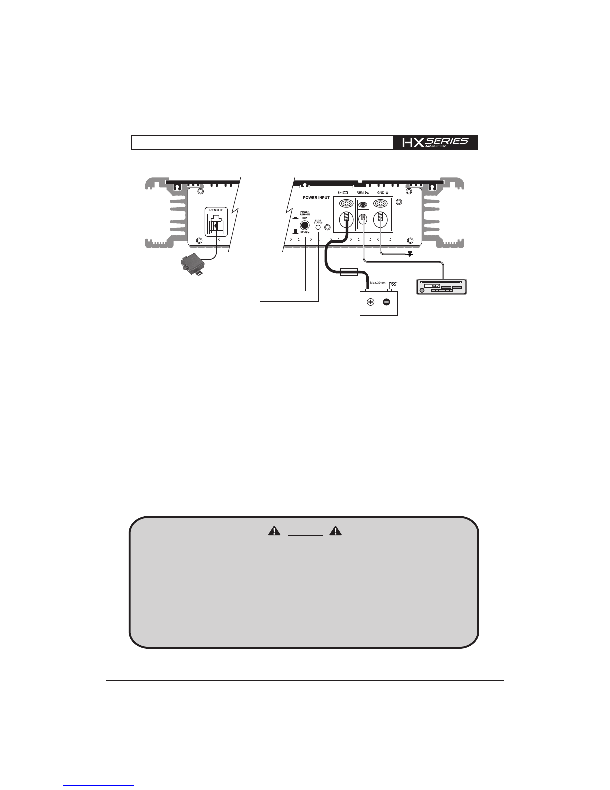
2. Ground connection (GND)
Connect the GND (ground) connection of the amplifier with the car chassis. Keep this cable as short as possible
(not longer than 50 cm) and use a suitable cross section (AWG sice 4 - 2).
Make sure, that the connection with the vehicle chassis is free of paint, dirt and dust.
3. +12 V Power connection (B+)
Connect the +12 V contact of the amplifier with the supply cable via a fuse directly to the vehicle battery.
Keep in mind, that the length of the cable from fuseholder to vehicle battery has to be a maximum of 30 cm.
Requirement for a perfect function of the amplifier is a qualitative high end fuse holder as well as a suitable cable
cross section (AWG sice 4 - 2). This fuse protects the amplifier and the vehicle against the possibility of a short
circuit in the power cable.
4. REM connection by cable
Connect the REM-terminal of the amplifier to the remote-output (automatic 12 V antenna-output) of the head unit.
Therefore use a 0,5 - 1,5 mm power cable and push the button „POWER REMOTE“ to „REM“
5. POWER REMOTE selectable button
If the radio (normally original radio) has no RCA output and remote output (automatic 12V antenne output) it is possible
to connect the speaker output from headunit direct in RCA input. The power remote button must be switched to „RCA“.
If the HX amp get a signal from headunit output, the amplifier will turn on.
6. FUSE STATUS LED
If the LED is shining the fuse is damaged.
HX 360.2 / HX 80..4
Power CONNECTION
to REMOTE Turn-on
from HEAD UNIT
BATTERY
GROUND
Fuse
-3 -
HEAD UNIT
Power remote selectable button
Fuse status LED
Wired Remote
Control RTC
(optional)
HX
Page 4

The HX series amplifier offers RCA-Inputs, which are connected through cinch cables with the
preamplifier-outputs of the head unit. The RCA-outputs provide the possibility to transfer the signal of
the head unit to a 2. amplifier via a cinch cable (for HX 360.2).
HX 360.2 | If the DIRECT INPUT button is pushed all features are disabled. Otherwise you can
use all features (Crossover, Phase Shift, Gain, RTC HX, HX Card, ...). The PHASE/RTC HX
button allows to select Phase Shift 0-360 ° or RTC HX Remote (optional) to control the amplifier
from the front of the car.It is possible to use three different crossover sections: High Pass, Low Pass
or Band Pass from 25-300 Hz. For the HX 360.2 you can also use HX Card.
HX 80.4 | If the DIRECT INPUT button is pushed all features are disabled. Otherwise you can use
all features (Crossover, Phase Shift, Gain, RTC HX, ...). The PHASE/RTC HX button allows to
select Phase Shift 0-360° or RTC HX Remote (optional) to control the amplifier from the front of the
car. It is possible to use two different crossover sections: HP 35-250 Hz/LP 50-300 Hz by pressing
FILTER FREQUENCY x1 of the front side, high pass frequency range will be increased 40 times from
35Hz~175Hz to 1400Hz~7000Hz. Likewise, by pressing FILTER FREQUENCY BUTTON of the rear
side, low pass frequency range will be increased 20 times from 50Hz~300Hz to 1000Hz~6000Hz.
In this regard, AUDIO SYSTEM Germany recommends to adjust your amplifier through a
specialized service center, dealer or a specialist.
.
-4 -
RCA CONNECTION
HX 360.2
HX 80..4
LPF HX card selectable button
12dB/24dB Slope selectable button
HX card port
PHASE/RTC HX selectable button
HPF HX card selectable button
INPUT selectable button
12dB/24dB Slope selectable button
LPF FILTER on/off button
PHASE/RTC HX selectable button
2 IN/4 IN selectable button
INPUT selectable button
HPF FILTER on/off button
HPF frequency x1, x40 selectable button
LPF frequency x1, x20 selectable button
25HZ 175Hz 50HZ 300Hz
Page 5

CH1
CH1/2-MONO
SUBWOOFER
Speaker connection
-5 -
HX 360.2
1-Channel Bridged
2-Channel Stereo
Tri-Mode
Speaker
Impeadance
2 ~ 8 ohm
Speaker
Impeadance
1 ~ 8 ohm
Speaker
Impeadance
4 ~ 8 ohm
Coil
CH1/2-MONO
SUBWOOFER
CH2
Page 6

CH3/4-MONO
SUBWOOFER
Speaker connection
2-Channel Bridged
CH1/2-MONO
SUBWOOFER
4-Channel Stereo
2-Channel Stereo + 1-Channel Mono Bridged
Speaker-
impedance
2 ~ 8 ohm
Speaker-
impedance
1 ~ 8 ohm
CH2
CH1
CH3
CH4
Speaker-
impedance
2 ~ 8 ohm
CH2
CH1
CH3/4-MONO
SUBWOOFER
-6 -
HX 80..4
Speaker-
impedance
1 ~ 8 ohm
Page 7

- ground connection professional connected?
- short-circuit caused by loudspeaker cable with vehicle
chassi (ground)?
- cinchcable (RCA) and/or loudspeaker cabel installed too
close to the power connection cable?
- cinch ground (RCA) of the head unit alright?
- ground connection professional connected?
- +12Vpowercable professional connected?
- remote cable professional connected?
- fuses inserted and alright?
- analyze voltage on the amplifier.
- cinch cable alright and professional connected?
- loudspeaker professional connected?
- head unit alright?
- amplifier too hot?
- short-circuit at the loudspeaker output?
- short-circuit caused by loudspeaker cable with vehicle
chassis (ground)?
- input voltage too high (e.g.faulty lighting dynamo)?
- impedance alright?
- loudspeaker error?
- adequate airflow of the amplifier?
! CAUTION !
After cooling down, the amplifier turns on automatically.
- ground professional connected?
- loudspeaker impedance alright?
! CAUTION !
Make sure when changing fuses to use the same value.
- input level control "GAIN" is set to match the head unit?
- output level control of the head unit alright?
- loudspeaker error?
- loudspeaker cable checked?
- crossover frequencies has been properly set?
(Check head unit, amplilfier, DSP, soundprozessor,
equalizer, frequency bandpassfilter...)
PROTECTION LED
ILLUMINATES GREEN
WHILE AMPLIFIER IS
SOUNDLESS
PROTECTION LED
ILLUMINATES RED
WHEN AMPLIFIER IS
POWERED UP
OVERHEATING
(PROTECTION LED
ILLUMINATES RED WHEN
AMPLIFIER IS POWERED UP)
ERROR IN AMPLIFIER
FUSE
SOUND TOO LOW OR
LOW-DISTORTED SOUND
HIGH HISS-ENGINE NOISE
IN SPEAKERS
trouble shooting
This power amplifier is featured with a efficient protection system to prevent any damages like over-heating,
overvoltage, short-circuit and Dc at the loudspeaker output.
Occurring an error the protection-LED will light in red.
In order to check the problem, first turn down all levels of the head unit, afterwards turn it off.
AMPLIFIER IS NOT
POWERED UP, NO LED
IS LIGHTENING
Please contact your specialist dealer if the amplifier is still not working after it has been
checked with the error list!
For warranty adjustement / repairs the original invoice has to be attached!
Opening the power amplifier is leading to a lost of warranty in either case!
CAUTION
-7-
Page 8

Power Supply Voltage
Rated Power Output at 14,4 V
-RMS power @ 4 ohm stereo
-RMS power @ 2 ohm stereo
-RMS power @ 1 ohm stereo
-RMS power @ 4 ohm bridged
-RMS power @ 2 ohm bridged
Signal to Noise Ratio
Low Pass Crossover
Low Pass Filter (HX CARD)
High Pass Crossover
High Pass Filter (HX CARD)
Phase Shift Control
Frequency Response
THD@RMS Watts
Channel Separation
Fuse Rating
Input Sensitivity
Dimensions
SpeCIFICATIONS
HX 360.2
10 -16 V
2x 360 W
2x 700 W
2x 1250 W
1x 1400 W
1x 2500 W
> 90 dB
50 Hz ~ 300 Hz
Optional
25 Hz ~ 175 Hz
Optional
0 ~ 360 degrees
10 Hz ~ 110 KHz (+/-1dB)
0.02%
75 dB
250 A
200 mV ~ 8 V (+/- 5%)
240(W) x 53(H) x 706(L)mm
Power Supply Voltage
Rated Power Output at 14,4 V
-RMS power @ 4 ohm stereo
-RMS power @ 2 ohm stereo
-RMS power @ 1 ohm stereo
-RMS power @ 4 ohm bridged
-RMS power @ 2 ohm bridged
Signal to Noise Ratio
Low Pass Crossover
High Pass Crossover
Phase Shift Control
Frequency Response
THD@RMS Watts
Channel Separation
Fuse Rating
Input Sensitivity
Dimensions
HX 80..4
10 -16 V
4x 80 W
4x 145 W
4x 250 W
2x 290 W
2x 500 W
> 90 dB
50 Hz ~ 300 Hz (Input-A)
50 Hz ~ 6 KHz (Input-B)
35 Hz ~ 7 KHz (Input-A)
35 Hz ~ 250 Hz (Input-B)
0 ~ 360 degrees
10 Hz ~ 80 KHz (+/-1dB)
0.02%
75 dB
100A
200 mV ~ 8 V (+/- 5%)
240(W) x 53(H) x 416(L)mm
 Loading...