

Page 1

MANUALE D’USO
I
Amplificatore di potenza audio
a due canali per auto
GB
USER'S GUIDE
Two-channel car audio
power amplifier
MANUEL D'UTILISATION
F
Amplificateur de puissance
audio à deux canaux pour
automobile
D
BEDIENUNGSANLEITUNG
Zweikanal-AudioLeistungsverstärker für das
Auto
E
MANUAL DE USO
Amplificador de potencia audio
de dos canales para
automóvil.
Page 2

Page 3

high pass low pass .
20222635150
off
off
hertz
hertz
on
on
preamplifierCrossover
L
455570
110
300
(mono)
4.3
0.7
0.4
0.26
0.17
l/r
rem
volt
mono
on
R
prt
speakers
L R
bridge
supply
gnd 12
fuses
30 A 30 A 30 A
SERIES
high pass low pass .
20222635150
off
off
hertz volt
hertz
on
on
preamplifierCrossover
L
455570
110
300
(mono)
4.3
0.7
0.4
0.26
0.17
l/r
rem
mono
on
R
prt
speakers
bridge
L R
supply
gnd 12
fuses
30 A
30 A
SERIES
crossover
lp
455570
hp
hertz volt
preamplifiercrossover
L
110
300
(mono)
4.3
0.7
0.4
0.26
0.17
l/r
off
on
mono
R
prt
supply
speakers
L
rem
bridge
on
cap
R
gnd
12
fuse
40 A
SERIES
preamplifiercrossover
L
lp
455570
110
300
hp
hertz
(mono)
4.3
0.7
0.4
0.26
0.17
l/r
off
volt
on
mono
R
prt
supply
speakers
L
rem
bridge
on
cap
R
gnd
12
fuse
25 A
Page 4

E D F
INTRODUCCIÓN
GTtrading le agradece su
elección, felicitándole por haber
elegido los productos
AUDIOSYSTEM.
Los amplificadores Twister
garantizan prestaciones
superiores en el plano eléctrico,
mecánico y sonoro,
manteniendo las características
anunciadas constantes en el
tiempo. GTtrading les desea
una feliz escucha.
EINLEITUNG
G.T. Trading bedankt sich für
den Vorzug ihrer Produkte, und
beglückwünscht Sie zur Wahl
der Produkte von
AUDIOSYSTEM.
Die Twister-Verstärker
garantieren hervorragende
Leistungen unter elektrischen,
mechanischen und klanglichen
Gesichtspunkten, und behalten
diese Eigenschaften im Verlauf
ihrer Lebensdauer konstant bei.
G.T. Trading wünscht gutes
Hörvergnügen.
INTRODUCTION
GTtrading vous remercie de
votre confiance et se félicite de
ce que vous ayez choisi un
produit AUDIOSYSTEM.
Les amplificateurs Twister
garantissent des performances
supérieures au niveau
électrique, mécanique et
acoustique. En outre, ils
conservent longuement les
caractéristiques qui sont
déclarées.
GTtrading vous souhaite une
bonne audition.
El manual de uso
Ha sido realizado para facilitar
una correcta instalación con el
fin de obtener el máximo de las
prestaciones del amplificador.
Contiene información y
procedimientos fundamentales
para el buen funcionamiento del
producto y de los dispositivos
conectados al mismo. Es
indispensable observar todas las
indicaciones con el fin de que se
garantice la seguridad de quien
efectúe la instalación y/o quien
utilice el producto.
El “Manual de uso” está dividido
en cuatro partes:
PARTE A:
REQUISITOS DE
SEGURIDAD
PARTE B:
DESCRIPCIÓN DEL
PRODUCTO
PARTE C:
INSTALACIÓN Y
CONEXIONES
PARTE D:
AJUSTES Y
UTILIZACIÓN
Benutzerhandbuch
Das vorliegende
Benutzerhandbuch wurde so
konzipiert, dass es Ihnen eine
korrekte Installation ermöglicht,
bei der die Leistungen des
Verstärkers bestmöglich zur
Geltung kommen. Es enthält
Informationen und grundsätzliche
Vorgehensweisen für die korrekte
Funktionsweise des Produkts und
der daran angeschlossenen
Vorrichtungen. Es ist unerlässlich,
alle Anweisungen zu befolgen,
sodass die Sicherheit desjenigen
gewährleistet ist, der die
Installation ausführt und/oder das
Produkt bedient.
Das Benutzerhandbuch ist in vier
Teile unterteilt:
TEIL A:
SICHERHEITSVORSCHRIFTEN
TEIL B:
PRODUKTBESCHREIBUNG
TEIL C:
INSTALLATION UND
ANSCHLÜSSE
TEIL D:
EINSTELLUNGEN UND
HANDHABUNG
Le manuel d'utilisation
Il est conçu pour assurer une
installation correcte qui
permettra à l'amplificateur de
vous fournir les meilleures
performances. Il présente des
informations et des procédures
fondamentales pour garantir le
bon fonctionnement du produit
et des dispositifs qui lui sont
raccordés.
Il est indispensable de respecter
toutes ses indications de façon
à garantir la sécurité de ceux qui
effectuent l'installation et de
ceux qui utilisent le produit.
Le « Manuel d'utilisation » se
partage en quatre parties:
PARTIE A :
CONSIGNES DE
SÉCURITÉ
PARTIE B :
DESCRIPTION DU
PRODUIT
PARTIE C:
INSTALLATION ET
CONNEXIONS
PARTIE D :
RÉGLAGES ET
UTILISATION
ES IMPORTANTE LEER ESTE
“MANUAL DE USO” Y
COMPRENDER BIEN TODAS
LAS PARTES.
4
DIE GEBRAUCHSANWEISUNG
SOLLTE UNBEDINGT
VOLLSTÄNDIG. DURCHGELESEN
UND VERSTANDEN WERDEN.
IL EST IMPORTANT QUE CE
“MANUEL D'UTILISATION”
SOIT LU ENTIÈREMENT ET
PARFAITEMENT ASSIMILÉ.
Page 5

GB I
INTRODUCTION
GTtrading thanks you for your
purchase, and would like to
congratulate you on choosing an
AUDIOSYSTEM product.
Twister amplifiers guarantee
superior performance levels in
terms of electrics, mechanics
and sound, keeping the
characteristics stated constant
through time.
GTtrading wishes you happy
listening.
INTRODUZIONE
GTtrading ringrazia per la
preferenza accordatale,
congratulandosi per aver scelto i
prodotti AUDIOSYSTEM.
Gli amplificatori T
garantiscono p
wister
restazioni
superiori sotto l’aspetto elettrico,
meccanico e sonoro,
mantenendo le caratteristiche
dichiarate costanti nel tempo.
GTtrading Vi augura un buon
ascolto.
The User's Guide
The user's guide was devised to
facilitate the correct installation
procedure so that you get the
most out of your new amplifier. It
contains information and vital
procedures for the correct
operation of the product and any
devices connected to it.
We recommend you follow the
instructions carefully, in order to
guarantee the safety of the
person in charge of installing
and/or using the product.
The “User's Guide” is divided
into four parts:
PART A:
SAFETY
PRECAUTIONS
PART B:
PRODUCT
DESCRIPTION
PART C:
INSTALLATION AND
CONNECTIONS
Il manuale d’uso
È stato realizzato in modo da
permetterVi una corretta
installazione al fine di ottenere il
massimo delle prestazioni
dall’amplificatore. Contiene
informazioni e procedure
fondamentali per il buon
funzionamento del prodotto e
dei dispositivi ad esso collegati.
E’ indispensabile osservarne
tutte le indicazioni, affinché
possa essere garantita la
sicurezza di chi opera
l’installazione e/o di chi utilizza il
prodotto.
Il “Manuale d’uso” e suddiviso in
quattro parti:
PARTE A:
PRESCRIZIONI DI
SICUREZZA
PARTE B:
DESCRIZIONE DEL
PRODOTTO
PARTE C:
INSTALLAZIONE E
COLLEGAMENTI
PART D:
ADJUSTMENTS AND
USE
THIS “USER'S GUIDE” MUST
BE READ AND
UNDERSTOOD IN FULL.
PARTE D:
REGOLAZIONI ED
UTILIZZO
E’ IMPORTANTE CHE
QUESTO “MANUALE D’USO”
VENGA LETTO E COMPRESO
IN OGNI SUA PARTE.
5
Page 6

E D F GB
Símbolos convencionales
En algunas de las imágenes
incluidas en este “Manual de uso”
se han introducido los
“SÍMBOLOS NORMALIZADOS”
descritos a continuación, con el
fin de subrayar las operaciones
que necesitan mayor atención.
Konventionelle Symbolik
In manchen Abbildungen, die in
diesem Benutzerhandbuch
aufgeführt wurden, sind
„GENORMTE SYMBOLE“
eingefügt worden, die im
Folgenden beschrieben werden.
Sie sollen Arbeiten unterstreichen,
bei denen größtmögliche
Aufmerksamkeit erforderlich ist.
Symbologie conventionnelle
Des « SYMBOLES
NORMALISÉS » ont été insérés
dans certaines des images qui
sont présentées dans ce «
Manuel d'utilisation » de façon à
insister sur les opérations qui
réclament une attention
particulière. Ces symboles
seront décrits par la suite.
REFERENCIA DE PÁGINA
Indica las páginas del manual
en las que se trata el tema
correspondiente.
PRECAUCIÓN ¡PELIGRO
GENERAL!
Indica que la operación descrita
presenta, si no se efectúa según
las normativas de seguridad, el
riesgo de provocar daños,
especificados en cada caso en
el texto y en el símbolo.
a) PRECAUCIÓN: ¡PELIGRO
DE INCENDIO!
b) PRECAUCIÓN: ¡PELIGRO
DE SUFRIR
QUEMADURAS!
c) PRECAUCIÓN: ¡PELIGRO
DE EXPLOSIÓN!
SEITENVERWEIS
Gibt dem Personal die Seiten
an, in denen im Handbuch
Themen behandelt werden, die
miteinander in Beziehung
stehen.
ACHTUNG! ALLGEMEINE
GEFAHR!
Weist das betreffende Personal
darauf hin, dass die
beschriebene Arbeit ein
Schadensrisiko darstellt, wenn
sie nicht unter Beachtung der
Sicherheitsnormen durchgeführt
wird, die von Fall zu Fall im Text
und beim Symbol erläutert
werden.
a) ACHTUNG
BRANDGEFAHR!
b) ACHTUNG
VERBRENNUNGSGEFAHR!
c) ACHTUNG
EXPLOSIONSGEFAHR!
RÉFÉRENCE PAGE
Signale a l’utilizateur les pages
du manuel qui traitent des sujets
corrélés.
ATTENTION DANGER
GÉNÉRAL!
Ce symbole indique au
personnel concerné que
l'opération décrite implique, si
elle n'est pas effectuée
conformément aux consignes de
sécurité, un risque de
dommages, précisés cas par
cas dans le texte et par le
symbole.
a) ATTENTION RISQUE
D'INCENDIE!
b) ATTENTION RISQUE DE
BRÛLURES!
c) ATTENTION RISQUE
D'EXPLOSION!
¡ADVERTENCIA!
Indica la información referida a
elementos que, en caso de no
ser respetados, pueden
ocasionar daños personales y/o
materiales.
¡NOTA!
Indica la información cuyo
contenido es de especial
consideración y/o importancia.
6
WARNUNG!
Diese Information weist das
betreffende Personal darauf hin,
dass Schäden an der Person
und/oder am Produkt
hervorgerufen werden können,
wenn der Inhalt nicht befolgt wird.
HINWEIS!
Weist das betreffende Personal
auf Informationen hin, dessen
Inhalt beachtet werden muss
und/oder wichtig ist.
AVERTISSEMENT!
Ce symbole fournit au personnel
concerné des informations dont
le contenu, s'il n'est pas
respecté, peut provoquer des
problèmes aux personnes et
et/ou au produit.
REMARQUE!
Ce symbole fournit au personnel
concerné des informations dont
le contenu est d'une importance
et/ou d'une teneur
fondamentale.
Page 7

Conventional symbols
Some of the diagrams included
in this “User's Guide” feature the
“STANDARDISED SYMBOLS”
described below, to highlight
operations that require more
caution.
I
Simbologia convenzionale
In alcune delle immagini
riportate in questo “Manuale
d’uso” sono stati inseriti i
“SIMBOLI NORMALIZZATI”
descritti in seguito, in modo da
sottolineare operazioni che
necessitano di maggiore
attenzione.
PAGE REFERENCE
This symbol warns about the
manual pages which describe
the same topic.
GENERAL HAZARD
WARNING!
This symbol warns the
technician that the operation
described - when not performed
in compliance with safety
standards - involves the risk of
causing damage, specified in
each symbol description.
a) FIRE HAZARD WARNING!
b) BURNS HAZARD
WARNING!
c) EXPLOSION HAZARD
WARNING!
RIFERIMENTO PAGINA
Segnala al personale le pagine
del manuale in cui si trattano
argomenti correlati.
ATTENZIONE
PERICOLO
GENERICO!
Segnala al personale
interessato che l’operazione
descritta presenta - se non
effettuata nel rispetto delle
normative di sicurezza - il rischio
di provocare danni, specificati di
volta in volta nel testo e nel
simbolo.
a) ATTENZIONE PERICOLO DI
INCENDIO!
b) ATTENZIONE PERICOLO DI
USTIONI!
c) ATTENZIONE PERICOLO DI
ESPLOSIONE!
a
b
c
CAUTION!
This symbol provides the
technician with information, the
contents of which - when not
observed - may cause personal
discomfort and/or product
malfunctions.
NOTE!
This symbol provides the
technician with information, the
contents of which are of
significant consideration and/or
importance.
AVVERTENZA!
Segnala al personale
interessato, informazioni il cui
contenuto - se non rispettato può provocare inconvenienti alla
persona e/o al prodotto.
NOTA!
Segnala al personale
interessato, informazioni il cui
contenuto è di rilevante
considerazione e/o importanza.
7
Page 8

ÍNDICE
INTRODUCCIÓN
El manual de uso
Simbología convencional
ÍNDICE
INHALTSVERZEICHNIS
EINLEITUNG
Das Benutzerhandbuch
Konventionelle Symbolik
INHALTSVERZEICHNIS
INTRODUCTION
Le manuel d'utilisation
Symbologie conventionnelle
SOMMAIRE
REQUISITOS DE SEGURIDAD
Antes de comenzar
Colocación
Fijación
Cableado
Alimentación
Conexiones y ajustes
DESCRIPCIÓN PRODUCTO
Embalaje y contenido
Descripción general
Entrada
Filtros
Salida
Alimentación
Sistema de protección
Supresor de interferencias
Refrigeración
ESPECIFICACIONES TÉCNICAS
Condiciones de medida
Diagrama esquemático
Dimensiones
PANEL DE CONTROL
CONEXIONES EN LA INSTALACIÓN
NORMAS GENERALES
Tipología de instalación
Selección del filtro
Impedancia de carga de salida
Filtros pasivos
EJEMPLOS DE CONFIGURACIONES
Estéreo
Mono
Trimode
ALIMENTACIÓN
SICHERHEITSVORSCHRIFTEN
Vor der Inbetriebnahme
Installation
Befestigung
Verkabelung
Stromversorgung
Anschlüsse und Einstellungen
PRODUKTBESCHREIBUNG
Verpackung und Inhalt
Allgemeine Beschreibung
Eingang
Filter
Ausgang
Stromversorgung
Sicherheitssystem
Entstörung
Kühlung
TECHNISCHE EIGENSCHAFTEN
Messbedingungen
Blockdiagramm
Abmessungen
STEUERUNG
INSTALLATION UND ANSCHLÜSSE
ALLGEMEINE REGELN
Anlagentypen
Filterauswahl
Impedanz Ausgangsladung
Passive Filter
KONFIGURATIONSBEISPIELE
Stereo
Mono
Trimode
STROMVERSORGUNG
CONSIGNES DE SÉCURITÉ
Avant de commencer
Emplacement
Fixation
Câblage
Alimentation
Connexions et réglages
DESCRIPTION DU PRODUIT
Confection et contenu
Description générale
Entrée
Filtrage
Sortie
Alimentation
Systeme de protection
Antiparasite
Refroidissement
SPÉCIFICATIONS TECHNIQUES
Conditions de mesure
Diagramme à blocs
Dimensions
PANNEAU DE COMMANDE
INSTALLATION CONNEXIONS
REGLES GENERAL
Typologies d'installation
Sélection du filtre
Impédance de la charge en sortie
Filtres passifs
EXEMPLES CONFIGURATIONS
Stéréo
Mono
Trimode
ALIMENTATION
AJUSTES, UTILIZACIÓN
Primera utilización
T estigos de funcionamiento
Regulación sensibilidad
Regulación crossover
Mantenimiento
ANOMALÍAS Y SOLUCIONES
Servicio Técnico Italia
Identificación del producto
DISTRIBUCIÓN CONTROLES
Referencia de página
Diagramas
REGULIERUNG UND GEBRAUCH
Erste Inbetriebnahme
Signalisierungen Betriebsanzeige
Einstellung der Empfindlichkeit
Regulierung des Crossover
Wartung
STÖRUNGEN UND LÖSUNG
T echnischer Kundendienst Italien
Identifizierung des Produkts
ANORDNUNG BEDIENELEMENTE
Seitenverweise
Schaltpläne
RÉGLAGES, UTILISATION
Premiere utilization
Voyants de fonctionnement
Réglage de la sensibilité
Réglages du répartiteur
Entretien
ANOMALIES ET SOLUTIONS
Assistance technique Italie
Identification du produit
DISPOSITION DES COMMANDES
Référence page
Schémas
Page 9
GB IE D F
INTRODUCTION
User's Guide
Conventional symbols
CONTENTS
INDICECONTENTSSOMMAIRE
INTRODUZIONE
Il manuale d’uso
Simbologia convenzionale
INDICE
4
4
6
8
SAFETY PRECAUTIONS
Before you begin
Positioning
Fastening
Wiring
Power supply
Connections and adjustments
PRODUCT DESCRIPTION
Packaging and contents
General description
Input
Crossovers
Output
Power supply
Protection system
Noise suppressor
Cooling
TECHNICAL SPECIFICATIONS
Measurement conditions
Block diagram
Dimensions
CONTROL PANEL
INSTALLATION CONNECTIONS
MAIN TIPS
System types
Filter selection
Output load impedance
Passive filters
CONFIGURATION SUGGESTIONS
Stereo
Mono
Trimode
POWER SUPPLY
PRESCRIZIONI DI SICUREZZA
Prima di iniziare
Collocazione
Fissaggio
Cablaggio
Alimentazione
Collegamenti e regolazioni
DESCRIZIONE PRODOTTO
Confezione e contenuto
Descrizione generale
Ingresso
Filtri
Uscita
Alimentazione
Sistema di protezione
Antidisturbo
Raffreddamento
SPECIFICHE TECNICHE
Condizioni di misura
Schema a blocchi
Dimensioni
PANNELLO DI CONTROLLO
INSTALLAZIONE COLLEGAMENTI
REGOLE GENERALI
Tipologie di impianto
Selezione del filtro
Impedenza carico in uscita
Filtri passivi
CONFIGURAZIONI D’ESEMPIO
Stereo
Mono
Trimode
ALIMENTAZIONE
10
12
14
16
18
20
22
24
24
24
26
26
28
28
28
30
32
32
32
34
44
44
44
46
46
48
48
50
52
54
ADJUSTMENTS, USE
First usage
Indicator LEDs
Sensitivity adjustment
Crossover adjustment
Maintenance
TROUBLESHOOTING
After-sales Service Italy
Product identification
CONTROLS LAYOUT
Page references
Diagrams
REGOLAZIONI, UTILIZZO
Primo utilizzo
Spie di funzionamento
Regolazione sensibilità
Regolazione crossover
Manutenzione
ANOMALIE E RIMEDI
Assistenza tecnica Italia
Identificazione prodotto
DISPOSIZIONE COMANDI
Riferimenti pagina
Schemi
56
56
58
60
62
64
70
70
72
74
98
Page 10

E D F GB
REQUISITOS DE
SEGURIDAD
Antes de comenzar
SICHERHEITSVORSCHRIFTEN
Vor der Inbetriebnahme
SÉCURITÉ
SAFETY PRECAUTIONSCONSIGNES DE
¡NOTA!
La instalación y la
puesta a punto del
amplificador debe
llevarla a cabo
exclusivamente
personal cualificado,
que debe haber leído y
comprendido el Manual
de Uso.
¡NOTA!
Durante la instalación y
los ajustes del
amplificador consultar
el “Manual de uso”
manteniendo la última
página abierta, donde
se representa el Panel
de Control al completo
y la numeración de
cada dispositivo que lo
compone.
¡ADVERTENCIA!
Antes de efectuar la
conexión de
dispositivos externos al
amplificador, consultar
la documentación
facilitada por el
fabricante de dichos
dispositivos.
HINWEIS!
Die Installation und
Einstellung des
Verstärkers darf nur von
qualifiziertem Personal
vorgenommen werden,
das dieses
Benutzerhandbuch
gelesen und verstanden
hat.
HINWEIS!
Schlagen Sie während
der Installation und
Regulierung des
Verstärkers im
„Benutzerhandbuch“
nach. Auf der letzten
Seite ist die gesamte
Steuerung mit der
Nummerierung aller
vorhandenen
Vorrichtungen
abgebildet.
WARNUNG!
Bevor Sie externe
Geräte anschließen, die
nicht zum Verstärker
gehören, ziehen Sie
bitte die vom
Gerätehersteller
ausgehändigte
Dokumentation zu
Rate.
REMARQUE!
L'installation et la mise
au point de
l'amplificateur doivent
être exécutées
exclusivement par du
personnel qualifié qui
devra avoir lu et
assimilé le Manuel
d'utilisation.
REMARQUE !
Pendant l'installation et
les réglages de
l'amplificateur, consulter
le Manuel d'utilisation et
laisser sa dernière page
ouverte: Cette page
représente le panneau
de commande complet
et la numérotation de
tous les dispositifs qui
le composent.
AVERTISSEMENT !
Avant de passer au
raccordement des
dispositifs externes,
consulter la
documentation fournie
par le fabricant du
dispositif en question.
NOTE!
The amplifier should be
installed and tuned only
by a Qualified
Technician, who has
read and understood
this User's Guide in full.
NOTE!
During the installation
and adjustment of the
amplifier, consult the
“User's Guide” while
keeping the last page
open: it contains a
detailed diagram of the
Control Panel and the
numbering of each
device it comprises.
CAUTION!
Before connecting any
external devices to the
amplifier, consult the
documentation provided
by the manufacturer of
the device itself.
¡ADVERTENCIA!
No abrir el amplificador,
no intentar repararlo.
En caso de necesidad,
dirigirse exclusivamente
al Distribuidor (punto de
venta), quien activará la
prestación del Servicio
Técnico. Cualquier tipo
de uso indebido
significa la pérdida
inmediata de la
garantía.
10
WARNUNG!
Öffnen Sie den
Verstärker nicht und
versuchen Sie nicht,
diesen zu reparieren.
Wenden Sie sich bei
Bedarf ausschließlich
an Ihren Händler, der
den Technischen
Kundendienst
informieren wird. Jede
unbefugte Änderung
bringt einen
unverzüglichen
Garantieverfall mit sich.
AVERTISSEMENT !
Ne pas ouvrir
l'amplificateur, ne pas
essayer de le réparer
soi-même. En cas de
besoin, s'adresser
directement au point de
vente qui contactera le
service d’Assistance
Technique.
Toute altération quelle
qu'elle soit provoquera
l'annulation immédiate
de la garantie.
CAUTION!
Do not open the
amplifier, on no account
should you attempt to
repair it. If repair work is
necessary, contact the
Retailer you purchased
it from, to activate the
Technical Service.
All tampering
immediately invalidates
the Warranty.
Page 11

I
PRESCRIZIONI DI
SICUREZZA
Prima di iniziareBefore you beginAvant de commencer
NOTA!
L’installazione e la
messa a punto
dell’amplificatore
devono essere eseguite
esclusivamente da
Personale Qualificato,
che deve avere letto e
compreso il Manuale
d’uso.
NOTA!
Durante l’installazione e
le regolazioni
dell’amplificatore
consultare il “Manuale
d’uso” mantenendo
l’ultima pagina aperta:
vi è raffigurato il
Pannello Comandi al
completo e la
numerazione di ogni
dispositivo che lo
compone.
AVVERTENZA!
Prima di effettuare
collegamento di
dispositivi esterni
all’amplificatore,
consultare la
documentazione fornita
dal costruttore del
dispositivo stesso.
AVVERTENZA!
Non aprire
l’amplificatore, non
tentare riparazioni. In
caso di necessità,
rivolgersi
esclusivamente al
Punto Vendita che
attiverà il servizio di
Assistenza Tecnica.
Ogni tipo di
manomissione
comporta il
decadimento immediato
della Garanzia.
11
Page 12

E D F GB
SEGURIDAD
SICHERHEITSVORSCHRIFTENREQUISITOS DE
InstallationColocación
SÉCURITÉ
Emplacement
SAFETY PRECAUTIONSCONSIGNES DE
¡ADVERTENCIA!
Los amplificadores
Twister están
construidos para
funcionar
exclusivamente en el
interior de vehículos
alimentados a 12
Voltios CC, en entornos
cuya temperatura varíe
entre 0 y +60 °C.
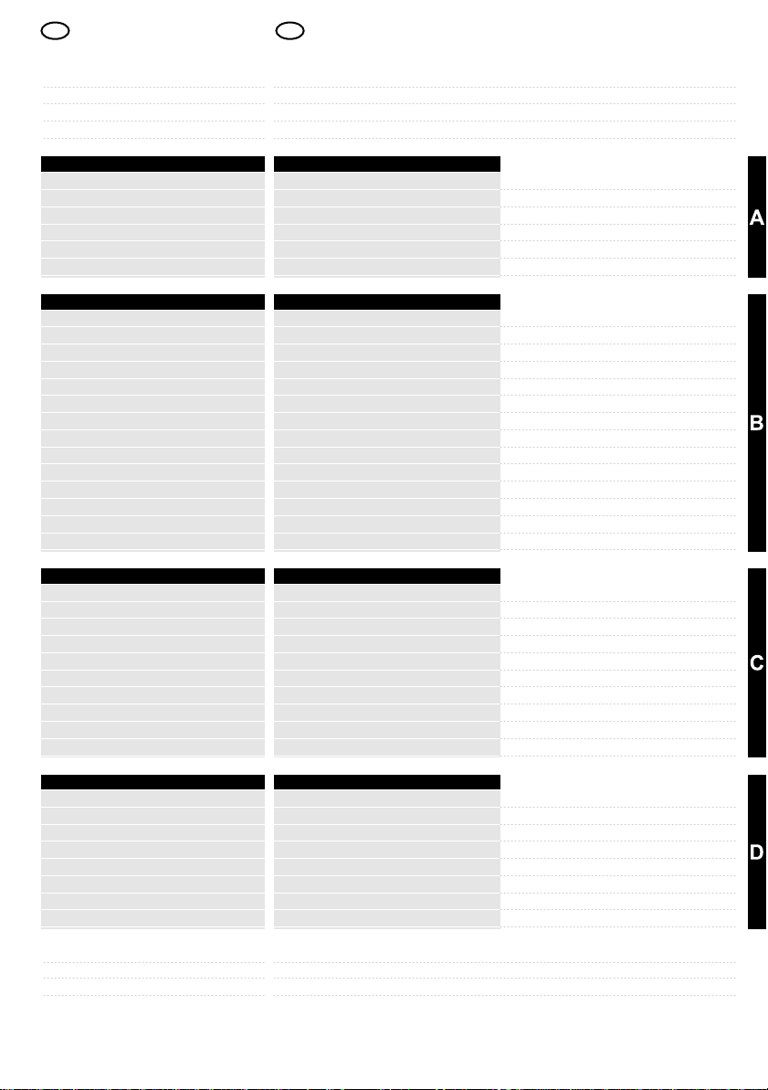
¡PRECAUCIÓN!
Instalar el amplificador
exclusivamente en el
interior del habitáculo o
del maletero. No
instalar el amplificador
en la zona del motor.
ADVERTENCIA!
No cubrir ni comprimir
el amplificador
WARNUNG!
Die Verstärker Twister
sind ausschließlich für
den Innenbereich von
Fahrzeugen konzipiert,
die eine
Stromversorgung von
12 Volt DC aufweisen.
Betriebstemperatur: 0
bis +60 °C.
ACHTUNG!
Installieren Sie den
Verstärker nur im
Wageninneren oder im
Kofferraum. Installieren
Sie den Verstärker nicht
im Motorraum.
WARNUNG!
Der Verstärker darf
keinem Druck
ausgesetzt sein und
nicht verdeckt werden.
AVERTISSEMENT !
Les amplificateurs
Twister sont
exclusivement
fabriqués pour opérer à
l'intérieur de véhicules
alimentés en 12 Volts
DC et dans des lieux
chent la température
est comprise entre 0 et
+60 °C.
ATTENTION !
Installer l'amplificateur
exclusivement à
l'intérieur de l'habitacle
ou du coffre. Ne pas
installer l'amplificateur
dans le compartiment
du moteur.
AVERTISSEMENT!
Ne pas couvrir, ni
écraser l'amplificateur.
CAUTION!
Twister amplifiers are
built to operate
exclusively inside
vehicles, powered at 12
Volts DC, in settings
with a temperature of
between 0 and +60 °C.
WARNING!
Install the amplifier
inside the passenger
compartment or boot
only. Do not install the
amplifier in the engine
compartment.
CAUTION!
Do not cover or crush
the amplifier.
¡ADVERTENCIA!
No introducir objetos ni
líquidos en el interior
del amplificador; no
impedir la rotación del
ventilador de
refrigeración.
12
WARNUNG!
Achten Sie darauf, dass
keine Fremdkörper oder
Flüssigkeiten in den
Verstärker gelangen.
Der Lüftungsventilator
muss frei drehen
können.
AVERTISSEMENT!
N'introduire ni objets, ni
liquides à l'intérieur de
l'amplificateur. Ne pas
entraver la rotation du
ventilateur de
refroidissement.
CAUTION!
Do not place objects or
pour liquids into the
amplifier and do not
obstruct the rotation of
the cooling fan.
Page 13
I
PRESCRIZIONI DI
SICUREZZA
CollocazionePositioning
AVVERTENZA!
Gli amplificatori Twister
sono costruiti per
operare esclusivamente
all’interno di autoveicoli
alimentati a 12 Volt DC,
in ambienti la cui
temperatura varia tra 0
e +60 °C.
ATTENZIONE!
Installare l’amplificatore
esclusivamente
all’interno dell’abitacolo
o del bagagliaio. Non
installare l’amplificatore
nel vano motore.
12 Volt DC
AVVERTENZA!
Non coprire o
schiacciare
l’amplificatore.
AVVERTENZA!
Non introdurre oggetti o
liquidi all’interno
dell’amplificatore, non
impedire la rotazione
della ventola di
raffreddamento.
13
Page 14

E D F GB
SEGURIDAD
¡ADVERTENCIA!
La colocación óptima
del amplificador es en
vertical, con el
ventilador en la parte
inferior, en una zona del
automóvil que tenga
buena ventilación.
SICHERHEITSVORSCHRIFTENREQUISITOS DE
BefestigungFijación
WARNUNG!
Optimal ist die vertikale
Positionierung des
Verstärkers in einem
Fahrzeugbereich, in
dem der Luftwechsel
möglich ist, wobei der
Ventilator nach unten
ausgerichtet ist.
SÉCURITÉ
Fixation
AVERTISSEMENT!
Le positionnement
optimal de
l'amplificateur est à la
verticale, avec le
ventilateur
en bas, dans une partie
de la voiture où le
renouvellement de l'air
est possible..
SAFETY PRECAUTIONSCONSIGNES DE
CAUTION!
The optimal positioning
of the amplifier is
vertically, with the fan
at the bottom, in an
area of the vehicle
where airing is possible.
¡PRECAUCIÓN!
El disipador puede
alcanzar una
temperatura superior a
los 80 °C; evitar el
contacto del
amplificador con
superficies y materiales
sensibles al calor.
¡PRECAUCIÓN!
Comprobar que, en la
unión de la zona de
fijación, no existan
elementos que puedan
sufrir daños provocados
por los tornillos o por
las operaciones de
fijación.
PROVOCAR
DISFUNCIONES EN EL
AUTOMÓVIL PUEDE
COMPROMETER
GRAVEMENTE LA
SEGURIDAD DEL
MISMO Y DE LAS
PERSONAS
ACHTUNG!
Der Kühlkörper kann
Temperaturen von über
80 °C erreichen.
Vermeiden Sie deshalb,
dass dieser mit
hitzeempfindlichen
Oberflächen oder
Materialien in
Berührung kommt.
ACHTUNG!
Versichern Sie sich,
dass in der Nähe des
Befestigungsbereiches
keine Elemente
vorhanden sind, die
durch die Schrauben
oder während des
Befestigungsvorgangs
beschädigt werden
können.
BESCHÄDIGUNGEN
AM FAHRZEUG
KÖNNEN DESSEN
SICHERHEIT SOWIE
DIE DER INSASSEN
SCHWER
GEFÄHRDEN.
ATTENTION !
Le dissipateur peut
atteindre une
température de plus de
80 °C. Éviter donc tout
contact de
l'amplificateur avec des
surfaces et des
matériaux sensibles à
la chaleur.
ATTENTION !
Veiller à ce que, au
niveau de la zone de
fixation, il n'y ait aucun
élément susceptible
d'être endommagé par
les vis ou par les
opérations de fixation.
ENDOMMAGER LA
VOITURE PEUT
COMPROMETTRE
GRAVEMENT SA
SÉCURITÉ ET
CELLE DES
PASSAGERS
WARNING!
The heat-sink can
reach temperatures in
excess of 80 °C, so try
to prevent any heatsensitive materials or
surfaces from coming
into contact with the
amplifier.
WARNING!
Check that the
fastening area is free
from any items that
could be damaged by
the screws or fastening
operations.
DAMAGE TO THE
CAR COULD
SERIOUSLY
COMPROMISE THE
SAFETY OF THE
VEHICLE AND ITS
PASSENGERS
¡PRECAUCIÓN!
Fijar firmemente el
amplificador en una
superficie que sea
capaz de soportar las
exigencias de su
entorno, utilizando los
cuatro orificios
previstos. Apretar los
tornillos de fijación.
14
ACHTUNG!
Befestigen Sie den
Verstärker mittels der
vier Bohrungen an einer
Oberfläche, die der
Belastung standhalten
kann.
Ziehen Sie die
Sicherheitsschrauben
gut an.
ATTENTION !
Fixer solidement
l'amplificateur sur une
surface à même d'en
supporter les
sollicitations et veiller à
bien utiliser les quatre
trous qui sont prévus.
Serrer les vis de
fixation.
WARNING!
Fasten the amplifier
securely to a surface
designed to withstand
its stresses, using all
four slots foreseen.
Tighten the fastening
screws.
Page 15

I
PRESCRIZIONI DI
SICUREZZA
FissaggioFastening
AVVERTENZA!
Il posizionamento
ottimale
dell’amplificatore è in
verticale, con la ventola
in basso, in una zona
della vettura dove sia
possibile il ricambio
d’aria.
ATTENZIONE!
Il dissipatore può
raggiungere una
temperatura superiore
agli 80 °C, evitare il
contatto
dell’amplificatore con
superfici e materiali
sensibili al calore.
ATTENZIONE!
Verificare che, in
corrispondenza del
zona di fissaggio, non vi
siano elementi che
possano subire danni
provocati dalle viti o
dalle operazioni di
fissaggio.
DANNEGGIARE LA
VETTURA PUÒ
COMPROMETTERE
GRAVEMENTE LA
SICUREZZA DELLA
STESSA E DELLE
PERSONE
ATTENZIONE!
Fissare saldamente
l’amplificatore ad una
superfice in grado di
sopportarne le
sollecitazioni,
utilizzando tutti e
quattro i fori previsti.
Serrare le viti di
fissaggio.
15
Page 16

E D F GB
SEGURIDAD
Cableado
¡PRECAUCIÓN!
Usar cables de
alimentación de sección
adecuada a la corriente
que circula por ellos y a
la longitud de la
conexión. La tabla
adjunta indica la
sección mínima que
se debe utilizar para un
funcionamiento con
seguridad.
Es una buena norma
usar siempre cables de
sección lo más grande
posibles.
SICHERHEITSVORSCHRIFTENREQUISITOS DE
Verkabelung
ACHTUNG!
Benutzen Sie nur
Stromversorgungskabel
mit Querschnitt und
Länge, die dem
zugeführten Strom und
der Verbindung
entsprechen. In der
nebenstehenden
Tabelle sind die
minimalen
Querschnitte für die
Gewährleistung der
Arbeitssicherheit
aufgeführt. Generell
wird empfohlen, Kabel
mit einem
SÉCURITÉ
ATTENTION !
Utiliser des câbles
d'alimentation d'une
section appropriée au
courant qui y passe et à
la longueur du
raccordement. Le
tableau ci-contre
indique la section
minimale à utiliser pour
opérer en toute
sécurité.
Il convient toujours
d'utiliser des câbles
présentant la plus
grande section
possible.
größtmöglichen
Durchmesser zu
verwenden.
¡NOTA!
El terminal de conexión
a MASA debe ser de
sección igual o superior
al usado para la
alimentación positiva.
HINWEIS!
Der Durchmesser des
ERDUNGSKABELS
muss mindestens
ebenso groß sein wie
das Pluskabel der
Stromversorgung.
REMARQUE !
Le câble de
raccordement à la
MASSE doit être d'une
section identique ou
supérieure à ce lui qui
est utilisé pour
l'alimentation positive.
¡ADVERTENCIA!
Efectuar las conexiones
y el ajuste de los
extremos
perfectamente. Utilizar
terminales adecuados y
fundas aislantes (no
suministradas). No
conectar el cable
pelado.
WARNUNG!
Nehmen Sie die
Verbindungen und
Abschlüsse jedes
einzelnen Kabels
fachgerecht vor.
Verwenden Sie
zweckmäßige
Kabelschuhe und
Isolierhüllen (nicht
mitgeliefert).
Verbinden Sie keine
AVERTISSEMENT !
Exécuter les
raccordements et les
extrémités de tous les
câbles dans les règles
de l'art.
Utiliser des cosses
appropriées et une
gaine isolante (non
fournis).
Ne pas brancher avec
un fil dé nudé.
abisolierten Drähte.
SAFETY PRECAUTIONSCONSIGNES DE
WARNING!
Use power supply
cables with a crosssection suitable for the
current load and
connection length. The
table opposite indicates
the minimum cross-
section to use for safe
operation.
It is good practice to
always use cables with
the largest possible
cross-section.
NOTE!
The connection cable to
GROUND should have
a cross-section that is
equal to or more than
that used for the
positive power supply.
CAUTION!
Make the connections
and terminations of
each cable according to
good practice.
Use suitable cable
terminals and an
insulating sheath (field
supply).
Do not connect to bare
wires.
¡ADVERTENCIA!
No colocar los cables
en ángulo recto, evitar
el contacto con chapas
que puedan cortar o
superficies, con el fin
de asegurar un buen
aislamiento. En caso
necesario usar gomas o
juntas protectoras (no
suministradas).
16
WARNUNG!
Positionieren Sie die
Kabel nicht rechtwinklig
gebogen. Vermeiden
Sie den Kontakt zu
scharfen Blechen oder
Oberflächen, die die
Isolierung beschädigen
können.Benutzen Sie
bei Bedarf Gummi- oder
Schutzdichtungen (nicht
mitgeliefert).
AVERTISSEMENT !
Ne pas positionner les
câbles à angle droit,
éviter le contact avec
des tôles coupantes ou
des surfaces qui
pourraient nuire à son
isolation. Si besoin est,
utiliser des caoutchoucs
ou des joints de
protection (non fournis).
CAUTION!
Do not place cables at
a right angle, avoid all
contact with sharp
sheet metal or surfaces
that may wear away the
insulation. If necessary,
use rubber washers or
protective seals (field
supply).
Page 17

I
PRESCRIZIONI DI
SICUREZZA
CablaggioWiringCâblage
ATTENZIONE!
Usare cavi di
alimentazione di
sezione adeguata alla
corrente che vi transita
ed alla lunghezza del
collegamento. La
tabella a fianco indica la
sezione minima da
utilizzare per operare in
sicurezza.
E’ buona regola usare
sempre cavi di sezione
più grande possibile.
NOTA!
Il cavo di collegamento
a MASSA deve essere
di sezione uguale
o superiore a quello
usato per
l’alimentazione positiva.
0-20
20-35
35-50
50-65
65-85
CURRENT (A)
85-105
105-125
125-150
MIN. SECTION (AWG/mm )
14/2 12/4
12/4 10/6
10/6
8/9 8/9
8/9 8/9
6/14
6/14
6/14
6/14
2/34 2/34 2/34
0-1.2 1.2-2.1 2.1-3.1 3.1-4.0 4.0-4.9 4.9-5.8 5.8-6.7
10/6 10/612/4 8/9 8/9 8/9
8/9 8/9
6/14
4/21
4/21
4/214/214/21
6/14
6/146/14
4/21
4/21 4/21 4/21
4/21
2/34 2/34 2/34
2/34 2/34
2/34 2/34
2/34
0/54 0/54
LENGTH (m.)
2
6/14 6/14
4/21 4/21
2/34 2/34
0/54
0/54 0/54
0/54
4/21
4/21
2/34
0/54
0/54
6.7-8.5
AVVERTENZA!
Eseguire le connessioni
e le terminazioni di ogni
cavo a regola d’arte.
Utilizzare capocorda
adatti e guaina isolante
(non forniti).
Non connettere a filo
spellato.
AVVERTENZA!
Non posizionare i cavi
ad angolo retto,
evitarne il contatto con
lamiere taglienti o
superfici in grado di
usurarne l’isolamento.
Se necessario usare
gommini o guarnizioni
di protezione (non
forniti).
17
Page 18

E D F GB
SEGURIDAD
FF
SICHERHEITSVORSCHRIFTENREQUISITOS DE
Stromversorgung Alimentación
SÉCURITÉ
SAFETY PRECAUTIONSCONSIGNES DE
¡ADVERTENCIA!
Antes de cualquier
acción de
mantenimiento, montaje
o desmontaje,
desconectar los bornes
de la batería.
¡PRECAUCIÓN!
Instalar siempre, en el
extremo del cable
positivo de alimentación
procedente de la
batería, un fusible de
valor aproximadamente
20% superior a la suma
de los fusibles
presentes en todos los
aparatos conectados a
dicho cable, lo más
cerca posible del borne
de la batería.
¡PRECAUCIÓN!
Cada vez que se
conecte la batería al
sistema eléctrico del
vehículo, prestar
atención a la polaridad
de los bornes. ¡No
invertir nunca la
polaridad!
WARNUNG!
Trennen Sie vor jedem
Wartungseingriff, jeder
Montage oder
Demontage die
Klemmen der
Stromversorgung von
der Batterie.
ACHTUNG!
Installieren Sie an dem
von der Batterie
kommenden Pluskabel
der Stromversorgung
und so nah wie möglich
an der Batterieklemme
immer eine Sicherung
mit einem Wert, der den
Schutz aller
Sicherungen der an das
Kabel angeschlossenen
Geräte um zirka 20 %
überschreitet.
ACHTUNG!
Achten Sie bitte bei
jedem Anschluss der
Batterie an die
elektrische Anlage des
Fahrzeugs auf die
korrekte Polarität der
Klemmen.
Invertieren Sie nie die
Polaritäten!
AVERTISSEMENT !
Avant toute intervention
d'entretien, de montage
et de démontage,
déconnecter les bornes
d'alimentation de la
batterie.
ATTENTION!
Installer toujours, sur le
câble positif
d'alimentation qui
provient de la batterie,
un fusible d'une valeur
approximativement 20%
supérieure à la somme
des fusibles présents
sur tous les appareils
raccordés au câble en
question, le plus près
possible de la borne de
la batterie.
ATTENTION !
Chaque fois que l'on
raccorde la batterie à
l'installation électrique
de la voiture, prêter
attention aux polarités
des bornes. Ne jamais
inverser les polarités !
CAUTION!
Before performing any
maintenance, assembly
or disassembly work,
disconnect the power
supply terminals from
the battery.
WARNING!
On the positive power
supply cable originating
from the battery, always
install a fuse with near
to 20% higher value
than the total fuses
installed on all the
devices connected to
the cable itself, as close
as possible to the
battery terminal.
WARNING!
Every time the battery is
connected to the
vehicle's electrical
system, pay attention to
the polarity of the
terminals. Never invert
the polarities!
¡PRECAUCIÓN!
Si se prevé conectar un
“Dispositivo de soporte
de alimentación”
(Condensador, etc.),
efectuar la instalación
DE ACUERDO CON
LAS INSTRUCCIONES
DEL CONSTRUCTOR.
SE DECLINA TODA
RESPONSABILIDAD
DERIVADA DEL USO
INDEBIDO DE
DISPOSITIVOS DE
ALIMENTACIÓN
EXTERNOS
18
ACHTUNG!
Ist der Anschluss eines
„externen
Stromversorgungs
systems“ vorgesehen
(Kondensator usw.),
nehmen Sie die
Installation bitte IN
ÜBEREINSTIMMUNG
MIT DEN
ANWEISUNGEN DES
HERSTELLERS vor.
WIR HAFTEN NICHT
FÜR SCHÄDEN, DIE
DURCH DEN
UNSACHGEMÄSSEN
GEBRAUCH
EXTERNER
STROMVERSOR-
GUNGS SYSTEME
VERURSACHT
WERDEN.
ATTENTION !
Si l'on veut raccorder un
« Dispositif de support à
l'alimentation »
(Condensateur, etc.),
exécuter l'installation
CONFORMÉMENT
AUX INSTRUCTIONS
DU FABRICANT.
NOUS DÉCLINONS
TOUTE
RESPONSABILITÉ EN
CAS D'UTILISATION
IMPROPRE DES
DISPOSITIFS
D'ALIMENTATION
EXTERNES.
WARNING!
If you plan to connect a
“Power supply
supporting device”
(such as a Power
Capacitor), install the
same ACCORDING TO
THE
MANUFACTURER'S
INSTRUCTIONS.
THE
MANUFACTURER
WILL NOT BE HELD
LIABLE IN THE
EVENT OF
INAPPROPRIATE USE
OF EXTERNAL
POWER SUPPLY
DEVICES
Page 19

I
PRESCRIZIONI DI
SICUREZZA
AlimentazionePower supplyAlimentation
AVVERTENZA!
Prima di qualsiasi
intervento di
manutenzione,
montaggio e
smontaggio, scollegare i
morsetti di
alimentazione dalla
batteria.
ATTENZIONE!
Installare sempre, sul
cavo positivo di
alimentazione che
proviene dalla batteria,
un fusibile di valore
circa 20% superiore alla
somma dei fusibili
presenti su tutti gli
apparecchi collegati al
cavo stesso, il più vicino
possibile al morsetto
della batteria.
ATTENZIONE!
Ogni volta che si collega
la batteria all’impianto
elettrico della vettura,
prestare attenzione alle
polarità dei morsetti.
Non invertire mai le
polarita!
ATTENZIONE!
Se si prevede di
collegare un
“Dispositivo di supporto
all’alimentazione”
(Condensatore, ecc.),
eseguire l’installazione
IN ACCORDO CON LE
ISTRUZIONI DEL
COSTRUTTORE.
SI DECLINA OGNI
RESPONSABILITÀ
DERIVATA DALL’USO
IMPROPRIO DI
DISPOSITIVI DI
ALIMENTAZIONE
ESTERNI
CAP
19
Page 20

E D F GB
E D F GB
SEGURIDAD
SICHERHEITSVORSCHRIFTENREQUISITOS DE
Anschlüsse und EinstellungenConexiones y regulaciones
SÉCURITÉ
SAFETY PRECAUTIONSCONSIGNES DE
¡ADVERTENCIA!
Efectuar la conexión de
MASA sólidamente,
apretando el terminal a
un punto metálico del
vehículo, limpiando
escrupulosamente
restos de barniz o
residuos.
¡ADVERTENCIA!
Utilizar cables de
longitud adecuada.
Evitar tracciones o
torsiones anormales en
las conexiones del
amplificador.
¡ADVERTENCIA!
Apretar con fuerza
todas las conexiones,
tanto en el amplificador
como en los
dispositivos conectados
al mismo.
WARNUNG!
Achten Sie darauf, dass der
ERDUNGSANSCHLUSS
solide ist. Schließen Sie
das Kabel an einen
metallenen Teil des
Fahrzeugs an, von dem
der Lack und/oder sonstige
Rückstände gewissenhaft
entfernt wurden.
WARNUNG!
Benutzen Sie Kabel mit
zweckmäßiger Länge.
Vermeiden Sie
ungewöhnliche
Dehnungen oder
Verdrehungen an den
Anschlüssen des
Verstärkers.
WARNUNG!
Nehmen Sie jeden
Anschluss am
Verstärker und den mit
diesem verbundenen
Geräten solide vor.
AVERTISSEMENT !
Effectuer la connexion
de MASSE solidement
serrant le câble qui
s'achève sur un point
métallique de la voiture
dont l'on aura éliminé
tous les résidus et ou
traces de peinture.
AVERTISSEMENT !
Utiliser des câbles
d'une longueur
appropriée. Éviter toute
traction ou torsion
anomale sur les
connexions de
l'amplificateur.
AVERTISSEMENT !
Serrer fermement
toutes les connexions,
tant sur l'amplificateur
que sur les dispositifs
qui lui sont raccordés.
CAUTION!
Make the GROUND
connection solid, by
tightening the cable end
to a metal part of the
vehicle, clean and bare
of any paint and/or
residue.
CAUTION!
Use cables of
appropriate length.
Avoid abnormal twisting
or pulling of the
amplifier connections.
CAUTION!
Tighten every
connection fully on both
the amplifier and any
devices connected to it.
¡ADVERTENCIA!
Con el fin de que el
sistema supresor de
interferencias
"E.NO.DE." funcione es
necesario que los
conectores RCA de
CUERPO METÁLICO
de entrada no entren en
contacto entre sí.
¡ADVERTENCIA!
Efectuar todas las
operaciones en los
selectores situados
sobre el Panel de
Control con el
amplificador apagado:
a) Apagar la fuente
b) Manipular
c) Encender la fuente
20
WARNUNG!
Damit das
Entstörsystem
„E.NO.DE.“
funktionieren kann,
dürfen die RCAEingangsanschlüsse
mit METALLGEHÄUSE
nicht miteinander in
Kontakt kommen.
WARNUNG!
Nehmen Sie jeden
Eingriff an den
Wählschaltern der
Steuerung bei
abgeschaltetem
Verstärker vor:
a) Schalten Sie die
Stromquelle ab
b) Führen Sie den
Eingriff aus
c) Schalten Sie die
Stromquelle wieder ein
AVERTISSEMENT!
Afin que le système
antiparasite “E.NO.DE.”
demeure efficace, il est
nécessaire que les
connecteurs à CORPS
MÉTALLIQUE RCA
d'entrée n'entrent pas
en contact les uns avec
les autres.
AVERTISSEMENT !
Effectuer les opérations
inhérentes aux
sélecteurs du Panneau
de Commande après
avoir éteint
l'amplificateur :
a) Isoler la source
b) Intervenir
c) Rétablir la source
CAUTION!
For the “E.NO.DE.”
radio interference
suppresser system to
remain effective, ensure
that the METAL
HOUSING RCA input
connectors do not come
into contact with one
another.
CAUTION!
Perform all settings on
the knobs situated on
the Control Panel with
the amplifier turned off:
a) Turn off the Source
b) Make the setting
c) Turn on the Source
Page 21

I21I
PRESCRIZIONI DI
SICUREZZA
Collegamenti e regolazioniConnections, adjustmentsConnexions et réglages
AVVERTENZA!
Effettuare la
connessione di MASSA
solida, serrando il cavo
terminato ad un punto
metallico della vettura,
ripulito al vivo da
vernice e/o residui.
AVVERTENZA!
Utilizzare cavi di
lunghezza adeguata.
Evitare trazioni o
torsioni anomale sulle
connessioni
dell’amplificatore.
AVVERTENZA!
Serrare con forza ogni
connessione, sia
sull’amplificatore che
sui dispositivi ad esso
collegati.
AVVERTENZA!
Affinché il sistema
antidisturbo “E.NO.DE.”
funzioni correttamente,
è necessario che i
connettori RCA a
CORPO METALLICO
di ingresso non entrino
in contatto tra loro.
AVVERTENZA!
Effettuare ogni
operazione sui selettori
posti sul Pannello
Comandi ad
amplificatore spento:
a) Spegnere la
sorgente
b) Operare
c) Accendere la
sorgente
a
OFF ON
b
c
Page 22

E D F GB
DESCRIPCIÓN DEL
PRODUCTO
PRODUKT-
BESCHREIBUNG
DESCRIPTION DU
PRODUIT
PRODUCT DESCRIPTION DESCRIZIONE DEL
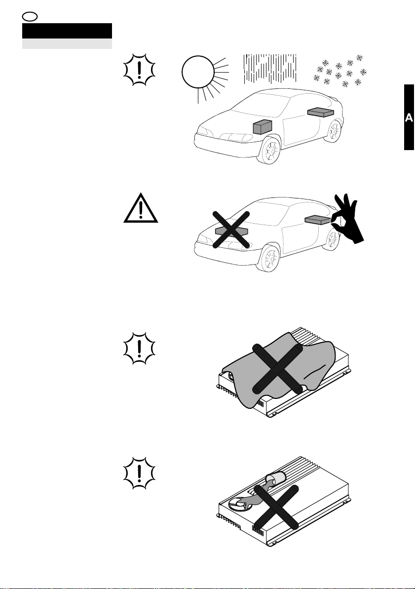
Embalaje y contenido
Los amplificadores
Twister están
embalados en una caja
de cartón diseñada
para proteger el
contenido.
No dañar ni tirar el
embalaje, conservarlo
para utilizaciones
futuras.
AL RECOGERLO
COMPROBAR QUE:
El embalaje esté
íntegro, el contenido
corresponda con el
especificado, el
producto no haya
sufrido daños. En caso
de ausencia de partes,
daños u otras
anomalías, contactar
inmediatamente con el
distribuidor (punto de
venta), citando el
modelo y el número de
serie situado en la parte
inferior del amplificador.
A: Amplificador Twister
F2>130 (1)
F2>190 (1)
F2>300 (1)
F2>500 (1)
Verpackung und Inhalt
Die Verstärker Twister
werden in schützende
Kartons verpackt.
Beschädigen Sie die
Verpackung nicht und
bewahren Sie diese für
die spätere
Verwendung auf.
KONTROLLIEREN SIE
BEI ERHALT DER
LIEFERUNG , DASS:
die Verpackung intakt ist,
der Inhalt den
Spezifikationen der
Dokumentation entspricht
und das Produkt keine
Beschädigungen aufweist.
Bei Fehlen oder
Beschädigung von Teilen
sowie anderen
Abweichungen setzen Sie
sich bitte sofort mit Ihrem
Händler in Verbindung.
Geben Sie hierbei sowohl
das Modell als auch die
Seriennummer an, die am
unteren Teil des Verstärkers
abgelesen werden kann.
A: Verstärker Twister
F2>130 (1)
F2>190 (1)
F2>300 (1)
F2>500 (1)
Confection et contenu
Les amplificateurs
Twister sont emballés
dans une boîte en
carton appropriée à la
protection de son
contenu.
Ne pas endommager, ni
jeter l'emballage. Le
conserver pour les
emplois futurs.
LORS DE LA
RÉCEPTION,
S'ASSURER QUE:
l'emballage est en
parfait état, le contenu
correspond aux
spécifications, le produit
n'a subi aucun
dommage.
En cas d'absence de
pièces et de présence
de dommages ou
d'autres anomalies,
contacter
immédiatement le point
de vente, en indiquant
le modèle et le numéro
de série qui se trouve
dans la partie inférieure
de l'amplificateur.
A: Amplificateur Twister
F2>130 (1)
F2>190 (1)
F2>300 (1)
F2>500 (1)
Twister amplifiers are
packed in a cardboard
box designed to protect
its contents.
Do not damage or
discard the packaging,
but keep it for future
use.
ON RECEIPT OF THE
AMPLIFIER, CHECK
THAT:
the packaging is intact,
the contents
correspond to the
specifications, the
product has not been
damaged in any way.
In the event of missing
parts, damages or other
faults, report the latter
to the Retailer you
purchased it from
immediately, making a
note of the model and
serial number marked
underneath the
amplifier.
A: Twister Amplifier
F2>130 (1)
F2>190 (1)
F2>300 (1)
F2>500 (1)
B: Tornillos de fijación
autorroscantes
3,9x19mm(4)
C: Fusibles de reserva
F2>130: 25A
Blanco(1)
F2>190: 40A
Naranja (1)
F2>300: 30A
Verde(2)
F2>500: 30A
Verde(3)
D: Certificado de
garantía (1)
E: Manual de uso(1)
22
B:Befestigungsschrauben
(selbstschneidend)
3,9x19mm(4)
C: Ersatzsicherungen
F2>130: 25A
Weiß(1)
F2>190: 40A
Orange(1)
F2>300: 30A
Grün(2)
F2>500: 30A
Grün(3)
D: Garantie(1)
E: Benutzerhandbuch(1)
B: Vis de fixation
autotaraudeuses
3,9x19mm(4)
C: Fusibles de secours
F2>130: 25A
Blanc(1)
F2>190: 40A
Orangé(1)
F2>300: 30A
Vert(2)
F2>500: 30A
Vert(3)
D: Certificat de
garantie(1)
E: Manuel d'utilisation(1)
B: Self-tapping
fastening screws
3,9x19mm(4)
C: Spare fuses
F2>130: 25A
White(1)
F2>190: 40A
Orange(1)
F2>300: 30A
Green(2)
F2>500: 30A
Green(3)
D: Warranty certificate(1)
E: User's guide(1)
Page 23
I
PRODOTTO
Confezione e contenutoPackaging and contents
Gli amplificatori Twister
sono confezionati in
una scatola di cartone
adatta a proteggerne il
contenuto.
Non danneggiare e non
gettare l’imballo,
conservarlo per utilizzi
futuri.
AL RICEVIMENTO
CONTROLLARE CHE:
l’imballo sia integro,il
contenuto corrisponda
alle specifiche, il
prodotto non abbia
subito danni.
In caso di parti
mancanti, danni o altre
anomalie, contattare
immediatamente il
Punto Vendita, citando
il modello ed il numero
di serie posto nella
parte inferiore
dell’amplificatore.
A
B
C
A: Amplificatore Twister
F2>130 (1)
F2>190 (1)
F2>300 (1)
F2>500 (1)
B: Viti di fissaggio
autofilettanti
3,9x19mm(4)
C: Fusibili di scorta
F2>130: 25A
Bianco(1)
F2>190: 40A
Arancio(1)
F2>300: 30A
Verde(2)
F2>500: 30A
Verde(3)
D: Certificato di
garanzia(1)
E: Manuale d’uso(1)
D
E
*
23
Page 24

E D F GB I
DESCRIPCIÓN DEL
PRODUCTO
PRODUKT-
BESCHREIBUNG
DESCRIPTION DU
PRODUIT
PRODUCT DESCRIPTION DESCRIZIONE DEL
Descripción general
Los Twister son
amplificadores de
potencia audio estéreo
para uso
automovilístico,
diseñados para
amplificar la señal
reproducida por fuentes
como: sintonizadores,
reproductores de
cassette, lectores de
CD, etc.
Entrada
El amplificador dispone
de una entrada RCA
estéreo, “LEFT”
(izquierda) y “RIGHT”
(derecha), en la que se
conecta la señal que
proviene de la fuente o
de los dispositivos de
procesamiento.
38,48,50,52
El potenciómetro
próximo a los
conectores permite la
regulación de la
sensibilidad
36,58
Allgemeine Beschreibung
Das Gerät Twister ist
ein Audio/StereoLeistungsverstärker für
Fahrzeuge und eignet
sich für die Verstärkung
von Signalen, die von
folgenden Quellen
erzeugt werden:
Tuner, Kassettendeck,
CD-Player usw.
Eingang
Der Verstärker verfügt
über einen RCAStereoeingang, “LEFT”
(links) und “RIGHT”
(rechts), über den der
Anschluss des von der
Quelle oder anderen
signalverarbeitenden
Geräten kommenden
Signals vorgenommen
werden kann.
38,48,50,52
Das Potenziometer
neben den Anschlüssen
ermöglicht die
Regulierung der
Signalempfindlichkeit.
36,58
Description générale
Les Twister sont des
amplificateurs de
puissance audio
stéréophoniques pour
automobiles. Ils sont
conçus pour amplifier le
signal reproduit par les
sources suivantes :
syntoniseurs, les
lecteurs de cassettes,
de CD, etc.
Entrée
L'amplificateur dispose
d'une entrée RCA
stéréophonique, “LEFT”
(Gauche) et “RIGHT”
(Droite), à laquelle doit
être raccordé le signal
qui provient de la
source ou des
éventuels dispositifs
d'élaboration.
38,48,50,52
Le potentiometre a
proximitè des
connecteurs permet le
réglage de la
sensibilité.
36,58
General description
Twisters are stereo
audio power amplifiers
for car use, designed to
amplify the signals
reproduced by sources
such as: tuners,
cassette players, CD
players, etc.
Input
The amplifier has a
stereophonic RCA
input, “LEFT” and
“RIGHT”, for the
connection of the signal
generated by the
source or any
elaboration devices
fitted.
38,48,50,52
The adjustment near
the connectors allow
you to set the
sensitivity.
36,58
Filtros
El amplificador dispone
de dispositivos de filtro
que limitan la banda de
frecuencia de salida. En
función de los ajustes,
se optimiza la señal
según el tipo de
altavoces conectados.
34,36,44,50,52,60
24
Filter
Der Verstärker verfügt
über
Filtervorrichtungen, die
das Frequenzband am
Ausgang beschränken.
Mit der Regulierung
optimieren Sie das
Signal für die
angeschlossenen
Lautsprechertypen.
34,36,44,50,52,60
Filtrage
L'amplificateur dispose
de systèmes de filtrage
qui limitent la bande de
fréquence en sortie. En
fonction des réglages,
on optimise le signal
pour le type de hautparleurs qui sont
raccordés.
34,36,44,50,52,60
Crossovers
The amplifier is fitted
with filter devices that
limit the output
frequency band.
According to the
adjustments made, the
signal is optimised for
the type of
loudspeakers
connected.
34,36,44,50,52,60
Page 25

PRODOTTO
Descrizione generale
I Twister sono
amplificatori di potenza
audio stereofonici per
uso automobilistico,
adatti ad amplificare il
segnale riprodotto da
sorgenti quali:
sintonizzatori,
riproduttori a cassette,
lettori CD ecc.
Ingresso
L’amplificatore dispone
di un ingresso RCA
stereofonico, “LEFT”
(Sinistro) e “RIGHT”
(Destro), al quale
collegare il segnale
proveniente dalla
sorgente o dagli
eventuali dispositivi di
elaborazione.
38,48,50,52
Il potenziometro vicino
ai connettori permette
la regolazione della
sensibilità.
36,58
Filtri
L’amplificatore dispone
di dispositivi filtro che
limitano la banda di
frequenza in uscita. In
base alle regolazioni, si
ottimizza il segnale per
il tipo di altoparlanti
collegati.
34,36,44,50,52,60
+6
LP Crossover
0
-8
-16
Decibel
-24
-32
-40
10 20 50 100 200 500 1k 2k 5k 10k 20k
Hertz
+6
0
-8
-16
Decibel
-24
-32
-40
10 20 50 100 200 500 1k 2k 5k 10k 20k
+6
0
-8
-16
Decibel
-24
-32
-40
10 20 50 100 200 500 1k 2k 5k 10k 20k
BP (band-pass)
HP Crossover LP Crossover
+
Hertz
HP Crossover
Hertz
25
Page 26

E D F GB I
DESCRIPCIÓN DEL
PRODUCTO
PRODUKT-
BESCHREIBUNG
PRODUIT
PRODUCT DESCRIPTIONDESCRIPTION DU
Salida
Los altavoces del
sistema se conectan a
los bornes “+” y “-” de
las salidas de potencia
”LEFT” y “RIGHT”.
40,46,48,50,52
En función de las
conexiones, es posible
obtener las tres
configuraciones base:
ESTÉREO:
Altavoces conectados
en modo Estéreo, en el
canal derecho y en el
canal izquierdo.
MONO PUENTEADO:
Altavoces conectados
en modo Mono,
transmitiendo la señal
"puenteada" en ambos
canales.
TRIMODE:
Altavoces conectados
tanto en modo Mono
como Estéreo.
Ausgang
Die Lautsprecher des
Systems werden an die
Klemmen “+” und “-” der
Leistungsausgänge
”LEFT” und “RIGHT”
angeschlossen.
40,46,48,50,52
Je nach Anschlusstyp
erzielen Sie drei
Basiskonfigurationen:
STEREO:
Die Lautsprecher sind
am rechten und linken
Kanal stereofon
ausgelegt.
MONO ÜBERBRÜCKT:
Die Lautsprecher sind
monofon ausgelegt.
Das
„Überbrückungssignal“
wird von beiden
Kanälen erfasst.
TRIMODE
Die Lautsprecher sind
sowohl monofon wie
stereofon ausgelegt.
Sortie
Le système des hautparleurs est raccordé
sur les bornes « + » et
« - », aux sorties de
puissance « LEFT » et
« RIGHT ».
40,46,48,50,52
En fonction des
connexions, on obtient
trois configurations
possibles:
STÉRÉO
Haut-parleurs
raccordés en mode
stéréophonique, sur le
canal droit et sur le
canal gauche.
MONO À PONT
Haut-parleurs
raccordés en mode
monophonique en
prélevant le signal « À
pont » sur les deux
canaux.
TRIMODE
Haut-parleurs
raccordés aussi bien en
mode Monophonique
qu'en Stéréophonique.
Output
The loudspeaker
system has to be
connected to the
terminals “+” and “-” of
”LEFT” and “RIGHT”
power outputs.
40,46,48,50,52
According to the
connections, the three
basic configurations are
obtained:
STEREO
Loudspeakers
connected in
Stereophonic mode, on
the right channel and
on the left channel.
BRIDGED MONO
Loudspeakers
connected in
Monophonic mode
taking the “bridged”
signal from both
channels.
TRIMODE
Loudspeakers
connected in both
Monophonic and
Stereophonic mode.
Alimentación
En la sección de
alimentación del
amplificador, se
conectan el terminal
POSITIVO procedente
de la batería, el
terminal de MASA y el
terminal REMOTE que
permite sincronizar el
encendido con la
fuente.
Los modelos F2>130 y
F2>190 disponen de un
terminal para la
conexión de
dispositivos accesorios
para apoyo de
alimentación
(CONDENSADORES
etc.).
42,54
26
Stromversorgung
Das von der Batterie
abgeleitete
PLUSKABEL, das
ERDUNGSKABEL und
das REMOTEKABEL,
das die
Einschaltsynchronisieru
ng mit der Quelle
ermöglicht, werden an
die
Stromversorgungseinhe
it des Verstärkers
angeschlossen.
Die Modelle F2>130
und F2>190 verfügen
über einen Anschluss
für Zusatzgeräte zur
Unterstützung der
Stromversorgung
(KONDENSATOR
usw.).
42,54
Alimentation
Sur la section
d'alimentation de
l'amplificateur,
raccorder le câble
POSITIF qui provient
de la batterie, le câble
de MASSE et le câble
REMOTE qui permet de
synchroniser l'allumage
avec la source.
Les modèles F2>130 et
F2>190 disposent d'une
benne pour le
raccordement de
dispositifs accessoires
pour le support de
l'alimentation
(CONDENSATEUR,
etc.).
42,54
Power supply
The POSITIVE cable of
the battery, the EARTH
cable and the REMOTE
cable that allows for
switch-on to be
synchronised with the
source are all
connected to the power
supply section of the
amplifier.
Models F2>130 and
F2>190 feature a
terminal for the
connection of
accessory power supply
supporting devices
(POWER CAPACITOR,
etc.).
42,54
Page 27

DESCRIZIONE DEL
PRODOTTO
Uscita
Gli altoparlanti del
sistema si collegano ai
morsetti “+” e “-” delle
uscite di potenza
”LEFT” e “RIGHT”.
40,46,48,50,52
In base alla
connessione, è
possibile ottenere le tre
configurazioni base:
STEREO
Altoparlanti collegati in
modo Stereofonico, sul
canale destro e sul
canale sinistro.
MONO A PONTE
Altoparlanti collegati in
modo Monofonico
prelevando il segnale “A
ponte” su entrambi i
canali.
TRIMODE
Altoparlanti collegati sia
in modo Monofonico
che Stereofonico.
STEREO
MONO (Bridged)
TRIMODE
bridge
bridge
bridge
“SPEAKERS”
L
“SPEAKERS”
L
“SPEAKERS”
L
speakers
R
R
R
Alimentazione
Alla sezione di
alimentazione
dell’amplificatore si
collegano il cavo
POSITIVO proveniente
dalla batteria, il cavo di
MASSA e il cavo
REMOTE che permette
di sincronizzarne
l’accensione con la
sorgente.
I modelli F2>130 e
F2>190 dispongono di
un terminale per il
collegamento di
dispositivi accessori per
il supporto
all’alimentazione
(CONDENSATORE
ecc.).
42,54
REM
27
Page 28

E D F GB I
DESCRIPCIÓN DEL
PRODUCTO
PRODUKT-
BESCHREIBUNG
DESCRIPTION DU
PRODUIT
PRODUCT DESCRIPTION DESCRIZIONE DEL
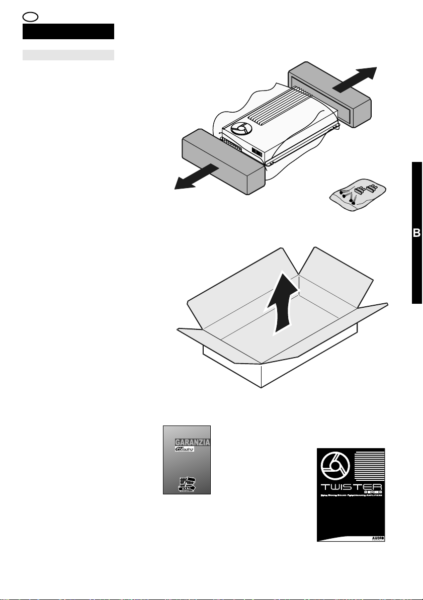
Sistema de protección
El estado operativo del
amplificador es
controlado por el
sistema "G.P.S." que,
en caso de
funcionamiento
irregular (cortocircuito,
tensión continua a los
bornes de salida,
“Bump” y
sobrecalentamiento),
interviene para proteger
el amplificador y el
sistema de audio
conectado. Cada
intervención es
visualizada mediante
los testigos luminosos
“STATUS” situados en
el Panel de Control.
38,56,64,66,68
Filtro antiparasitario
Los Twister disponen
de un sistema de
circuitos que suprime
las interferencias
eléctricas y
electromagnéticas
generadas por el
vehículo. "E.NO.DE."
evita que las mismas se
introduzcan en el
sistema de audio,
garantizando una
reproducción exenta de
ruidos y reduciendo el
tiempo de instalación.
20
Refrigeración
El sistema de
refrigeración de los
Twister está formado
por un disipador y
ventiladores.
"THERMOSPEED" es
el dispositivo integrado
que regula la velocidad
de rotación,
adecuándola a la
temperatura del propio
amplificador.
62
28
Sicherheitssystem
Der Betriebszustand
des Verstärkers wird
über das System
„G.P.S.“ kontrolliert, das
bei Störungen
(Kurzschluss,
Gleichspannung an den
Ausgangsklemmen,
Bump-Effekt und
Überhitzung) eingreift
und den Verstärker
sowie das
angeschlossene
Audiosystem schützt.
Jeder Eingriff wird über
die „STATUS” LEDs an
der Steuerung
angezeigt.
38,56,64,66,68
Entstörung
Die Verstärker Twister
sind mit einem
Schaltsystem
ausgestattet, das die
vom Fahrzeug
erzeugten elektrischen
und
elektromagnetischen
Störungen abdämpft.
„E.NO.DE.” verhindert,
dass die Störungen das
Audiosystem erreichen
und gewährleistet somit
eine Wiedergabe ohne
Störgeräusche sowie
verkürzte
Installationszeiten.
20
Kühlung
Das Kühlsystem von
Twister besteht aus
einem Kühlkörper und
Lüftern.
„THERMOSPEED” ist
eine integrierte
Vorrichtung, die die
Lüftergeschwindigkeit
reguliert und an die am
Verstärker erfasste
Temperatur anpasst.
62
L'état de marche de
l'amplificateur est
contrôlé par le système
“G.P.S.” qui, en cas de
fonctionnement
irrégulier (court-circuit,
tension continue sur les
bornes de sortie,
«bump» d'allumage et
surchauffe), intervient
pour protéger
l'amplificateur et le
système audio qui lui
est raccordé. Chaque
intervention est
signalée par les voyants
lumineux “STATUS”
situés sur le panneau
de commande.
38,56,64,66,68
Les Twister adoptent
une circuiterie qui
supprime les parasites
électriques et
électromagnétiques
produits par la voiture.
“E.NO.DE.” les
empêche de s'insérer
dans le système audio
en garantissant ainsi
une reproduction
exempte de
ronflements et en
réduisant les temps
d'installation.
20
Le système de
refroidissement des
Twister se constitue
d'un dissipateur et de
ventilateurs,
“THERMOSPEED” est
le dispositif intégré qui
en règle la vitesse de
rotation en l'adaptant à
la température présente
sur l'amplificateur.
62
The operating status of
the amplifier is
controlled by the
“G.P.S.” system which,
in the event of
malfunction (Shortcircuit, constant voltage
to the output terminals,
turn-on “bumps” and
overheating),
intervenes in order to
protect the amplifier
and the audio system
connected to it. Each
time the system
intervenes, this is
displayed on the
“STATUS” indicator
LEDS on the Control
Panel.
38,56,64,66,68
Twister amplifiers are
fitted with a circuit
system that suppresses
any electrical and
electromagnetic
interference generated
by the vehicle.
“E.NO.DE.” prevents it
from entering the audio
system, thereby
guaranteeing an audio
reproduction that is free
from buzzing and
cutting down the
installation time.
20
The cooling system
devised for Twister
amplifiers is composed
of a dissipator and fans,
the “THERMOSPEED”
integrated device
regulates the speed of
rotation of fans
according to the
temperature measured
on the amplifier.
62
Page 29
PRODOTTO
Sistema di protezioneProtection systemSysteme de protection
Lo stato operativo
dell’amplificatore è
controllato dal sistema
“G.P.S.” che, in caso di
funzionamento
irregolare
(Cortocircuito, tensione
continua ai morsetti
d’uscita, “Bump” di
accensione e
surriscaldamento),
interviene in modo da
salvaguardare
l’amplificatore ed il
sistema audio
collegato. Ogni
intervento viene
visualizzato mediante le
spie luminose
“STATUS” poste nel
Pannello Comandi.
38,56,64,66,68
AntidisturboNoise suppressorAntiparasite
I Twister adottano un
sistema circuitale che
sopprime i disturbi
elettrici ed
elettromagnetici
generati dalla vettura.
“E.NO.DE.” ne evita
l’inserimento nel
sistema audio
garantendo una
riproduzione priva di
ronzii e riducendo i
tempi di installazione.
20
G.P.S.
GLOBAL PROTECTION SYSTEM
STAT SU
E.NO.DE.
ELECTROMAGNETIC NOISE DESTROYER
RaffreddamentoCoolingRefroidissement
Il sistema di
raffreddamento dei
Twister è formato da
dissipatore e ventole,
“THERMOSPEED” è il
dispositivo integrato
che ne regola la
velocità di rotazione
adeguandola alla
temperatura rilevata
sull’amplificatore.
62
THERMOSPEED
ACTIVE FORCED COOLING SYSTEM
29
Page 30

E D F GB
ESPECIFICA TÉCNICAS
Potencia Estereo RMS
@4ohm
Potencia Estereo RMS
@2ohm
Potencia estereo dinamica
@2ohm
Potencia mono puentada
RMS @4ohm
Potencia mono puentada
RMS @2ohm Subwoofer
Impedencia de carga min.
Estereo
Impedencia de carga min.
Mono puentado Subwoofer
Factor de amortiguamjento
@4ohm
Intervalo de sensibilidad
de entrada
Impedancia de entrada
Filtro [cantidad] tipo
Banda de frecuencia del
filtro
Pendiente del filtro
Respuesta frecuencia -3dB
Distorsion THD @1KHz -
90% potencia nom. 4ohm
Distorsion DIM -
90% potencia nom. 4ohm
Relación señal/ruido -
10Hz÷22KHz - 90% potencia
nom.
Relación señal/ruido
pesado "A" - 10Hz÷22KHz 90% potencia nom.
Intervalo de tensión de
alimentación
Sección mínima del cable de
alimentación para 5 m.
de longitud (Metro)
Sección mínima del cable de
alimentación para 5 m.
de longitud (US)
Máxima corriente absorbida
Estéreo @4ohm
Máxima corriente absorbida
Mono puenteado @4ohm
Corriente en reposo: sin
señal de entrada
Corriente mínima absorbida:
amplificador apagado
Fusibles
Peso
Dimensiones
TECH. EIGENSCHAFTEN
Stereoleistung RMS
bei 4 Ohm
Stereoleistung RMS
bei 2 Ohm
Dynamische Stereoleistung
bei 2 Ohm
Monoleistung überbrückt
RMS bei 4 Ohm
Monoleistung überbrückt
RMS bei 2 OhmSubwoofer
Min. Belastungsimpedanz
Stereo
Min. Belastungsimpedanz
Mono überbrückt Subwoofer
Dämpfungsfaktor
bei 4 Ohm
Intervall
Eingangsempfindlichkeit
Eingangsimpedanz
Filter [Anzahl] Typ
Bandweite Filtereffekt
Filterpendenz
Frequenzgang -3dB
Verzerrungsfaktor THD 1KHz
90% Nennleistung 4Ohm
Verzerrungsfaktor DIM - 90%
Nennleistung 4 Ohm
Signal-Rausch-Verhältnis -
10Hz-22KHz 90 %
Nennleistung
Signal-Rausch-Verhältnis
gewichtet „A" - 10Hz-22KHz
90 % Nennleistung
Intervall
Versorgungsspannung
Min. Durchmesser
Stormversorgungskabel
Länge: 5 m - metrisch
Min. Durchmesser
Stormversorgungskabel
Länge: 5 m - US
Maximale Stromaufnahme
Stereo bei 4 Ohm
Maximale Stromaufnahme
Mono überbrückt bei 4 Ohm
Ruhestrom ohne
Eingangssignal
Minimale Stromaufnahme ausgeschaltetem Verstärker
Sicherungen
Gewicht
Abmessungen
SPECIFICATION TECH.
Puissance Stéréo RMS
@4ohm
Puissance Stéréo RMS
@2ohm
Puissance Stéréo
Dynamique @2ohm
Puissance Mono à pont
RMS @4ohm
Puissance Mono à pont
RMS @2ohmSubwoofer
Impédance de charge mini
Stéréo
Impédance de charge mini
Mono à pont Subwoofer
Facteur d'amortissement
@4ohm
Intervalle de sensibilité
d'entrée
Impédance d'entrée
Filtre [quantité] type
Bande d'intervention du filtre
Pente du filtre
Réponse de fréquence -3dB
Distorsion THD @1KHz -
90% puissance nom. 4ohm
Distorsion DIM - 90% -
puissance nom. 4ohm
Rapport Signal/Bruit -
10Hz¸22KHz - 90%
puissance nom.
Rapport Signal/Bruit pesé
”A” - 10Hz¸22KHz - 90%
puissance nom.
Intervalle de tension
d'alimentation
Section minimale du câble
d'alimentation pour 5 m de
longueur - Métrique
Section minimale du câble
d'alimentation pour 5 m de
longueur - US
Courant maximal absorbé
Stéréo @4ohm
Courant maximal absorbé
Mono à pont @4ohm
Courant au repos sans
signal en entrée
Courant minimal absorbé amplificateur éteint
Fusibles
Poids
Dimensions
30
SPECIFICATIONS
RMS Stereo power
@4ohm
RMS Stereo power
@2ohm
Dynamic Stereo power
@2ohm
RMS Mono bridged power
@4ohm
RMS Mono bridged power
@2ohmSubwoofer
Min. Stereo impedance load
Min. Mono bridged
impedance load Subwoofer
Damping factor @4ohm
Input sensitivity range
Input impedance
Crossover [quantity] type
Crossover cut frequency
range
Crossover slope
Frequency response -3dB
THD distortion @1KHz -
90% 4ohm nom. power
DIM distortion -
90% 4ohm nom. power
Signal/Noise ratio -
10Hz÷22KHz 90% nom. power
Signal/Noise ratio "A"
weighted - 10Hz÷22KHz 90% nom. power
Power supply range
Minimum cable size
for 5 mt. long - Metric
Minimum cable size
for 5 mt. long - US
Max current requirement
Stereo @4ohm
Max current requirement
Mono bridged @4ohm
Idle current
Standby current
Fuses
Weight
Dimensions
Page 31

I
SPECIFICHE TECNICHE
Potenza Stereo RMS
@4ohm
Potenza Stereo RMS
@2ohm
Potenza Stereo Dinamica
@2ohm
Potenza Mono a ponte RMS
@4ohm
Potenza Mono a ponte RMS
@2ohm Subwoofer
Impedenza di carico min.
Stereo
Impedenza di carico min.
Mono a ponte Subwoofer
Fattore di smorzamento
@4ohm
Intervallo sensibilità
d'ingresso
Impedenza d'ingresso
Filtro [quantità] tipo
Banda di intervento del Filtro
Pendenza del Filtro
Risposta di frequenza -3dB
Distorsione THD @1KHz -
90% potenza nom. 4ohm
Distorsione DIM - 90%
potenza nom. 4ohm
Rapporto Segnale/Rumore -
10Hz÷22KHz - 90% potenza
nom.
Rapporto Segnale/Rumore
pesato "A" - 10Hz÷22KHz 90% potenza nom.
Intervallo tensione di
alimentazione
Sezione min. del cavo di
alimentazione per 5 mt. di
lunghezza - Metrico
Sezione min. del cavo di
alimentazione per 5 mt. di
lunghezza - US
Massima corrente assorbita
Stereo @4ohm
Massima corrente assorbita
Mono a ponte @4ohm
Corrente a riposo - senza
segnale in ingresso
Corrente minima assorbita amplificatore spento
Fusibili
Peso
Dimensioni
_
Watt
Watt
Watt
Watt
Watt
Ohm
Ohm
-
V
Kohm
Hz
dB/oct.
Hz
%
%
dB
dB
Volt
2
mm
AWG
A
A
A
mA
A
Kg
mm
F2 > 130
65 x2
110 x2
128 x2
220 x1
350 x1
2
2
>400
0,17÷4,3
>11
[1] HP o LP
45÷300
12
5÷100.000
<0,05
<0,005
94
97
10,5÷16
8
8
15
25
0,64
0,001
1X 25A
1,7
220x180x50
F2 > 190
100 x2
155 x2
200 x2
320 x1
520 x1
2
2
>400
0,17÷4,3
>11
[1] HP o LP
45÷300
12
10÷105.000
<0,025
<0,005
94
97
10,5÷16
8
8
20
38
0,65
2,00
1X 40A
1,7
220x180x50
F2 > 300
150 x2
240 x2
320 x2
500 x1
780 x1
2
2
>400
0,17÷4,3
>11
[1] HP + [1] LP
(HP 20÷150) +
(LP 45÷300)
12
10÷165.000
<0,025
<0,015
103
106
10,5÷16
12
6
32
56
0,75
2,00
2X 30A
2,8
220x320x50
F2 > 500
230 x2
390 x2
475 x2
800 x1
1250 x1
2
2
>400
0,17÷4,3
>11
[1] HP + [1] LP
(HP 20÷150) +
(LP 45÷300)
12
10÷160.000
<0,02
<0,03
104
106
10,5÷16
21
4
46
84
1,32
2,00
3X 30A
4,6
220x550x50
31
Page 32

E D F GB I
DESCRIPCIÓN DEL
PRODUCTO
PRODUKT-
BESCHREIBUNG
DESCRIPTION DU
PRODUIT
PRODUCT DESCRIPTION DESCRIZIONE DEL
Condiciones de medida
(Si no se especifica de
otra forma).
Tensión: 14,4 Volt
Temperatura: 25°C
THD: 0,3%
Tolerancia: ±5%
Tipo de carga:
Resistiva pura
Diagrama esquemático
Representación gráfica
simplificada de las
funciones
L
INPUT
R
LLR
STEREO / MONO Pre - AMPLIFIER
Messbedingungen
(Sofern nicht anders
angegeben).
Spannung: 14,4 Volt
Temperatur: 25°C
THD: 0,3%
Toleranz: ±5%
Lasttyp:
Rein ohmisch
Blockdiagramm
Vereinfachte grafische
Darstellung der
Funktionen
L
LEVELLEVEL
(Sauf indication
différente).
Tension: 14,4 Volt
Température: 25°C
THD: 0,3%
Tolérance: ±5%
Type de charge:
Résistif pur
Diagramme à blocs
Représentation
graphique simplifiée
des fonctions
G
HP or LP FILTER
(Unless otherwise
specified).
Voltage: 14,4 Volt
Temperature: 25°C
THD: 0,3%
Tolerance: ±5%
Load type: Pure
resistive
Simplified graphic
representation of the
functions
G
Power - AMPLIFIER
L
OUTPUT
R
32
AbmessungenDimensiones
4,5 mm
180 mm
138 mm
50 mm
200 mm
210 mm
220 mm
SERIES
SERIES
statusinput supplyoutput
preamplifiercrossover
lp
455570
110
300
4.3
0.7
0.4
0.26
0.17
l/r
off
hp
hertz
volt
on
mono
supply
speakers
L
L
rem
(mono)
R
prt
cap
bridge
12
R
gnd
on
fuse
high pass low pass .
off
on
preamplifierCrossover
L
20222635150
off
hertz
on
(mono)
4.3
0.7
0.4
0.26
0.17
455570
110
300
l/r
hertz
volt
mono
R
4,5 mm
320 mm
280 mm
50 mm
200 mm
210 mm
212 mm
SERIES
supplyoutputinput statusrem
speakers
bridge
rem
on
prt
L R
supply
gnd 12
fuses
30 A
30 A
Page 33

PRODOTTO
Condizioni di misuraConditions de mesure Measurement conditions
(Se non diversamente
specificato).
Tensione: 14,4 Volt
Temperatura: 25°C
THD: 0,3%
Tolleranza: ±5%
Tipo di carico: Resistivo
puro
Schema a blocchiBlocks diagrams
Rappresentazione
grafica semplificata
delle funzioni
L
INPUT
R
LLR
L
STEREO / MONO LP FILTERHP FILTER
LEVEL
G
Pre - AMPLIFIER
DimensioniDimensions Dimensions
4,5 mm
input supplyoutputstatusrem
550 mm
508 mm
G
Power - AMPLIFIER
L
OUTPUT
R
50 mm
200 mm
210 mm
212 mm
high pass low pass .
20222635150
off
off
hertz
on
on
preamplifierCrossover
L
(mono)
4.3
0.7
0.4
0.26
0.17
455570
110
300
l/r
hertz
rem
volt
mono
on
R
prt
speakers
L R
bridge
supply
gnd 12
fuses
30 A
30 A 30 A
33
Page 34

E D F GB I
DESCRIPCIÓN DEL
PRODUCTO
PRODUKT-
BESCHREIBUNG
STEUERUNGPANEL DE CONTROL
PRODUIT
PRODUCT DESCRIPTIONDESCRIPTION DU
CONTROL PANELPANNEAU DE COMMANDE
SELECCIÓN DEL TIPO
DE FILTRO
CROSSOVER
Selecciona el tipo de
filtro crossover en
PASA BAJO “LP” o
PASA ALTO “HP”.
44,50,60
CONTROL DE LA
FRECUENCIA DE
TRABAJO
Regula el punto de
frecuencia en el que el
filtro crossover efectúa
su labor.
50,60
ACTIVACIÓN /
DESACTIVACIÓN DEL
FILTRO CROSSOVER
Pone en marcha o
anula la acción del filtro
crossover.
50,52,60
WAHL DES
CROSSOVERFILTERS
Schaltet den
Crossover-Filter auf
TIEFPASS „LP“ oder
HOCHPASS „HP“.
44,50,60
EINSTELLUNG DER
INTERVENTIONSFREQUENZ
Reguliert den
Frequenzpunkt, an dem
sich der CrossoverFilter einschaltet.
50,60
AKTIVIERUNG/DEAKTIVIERUNG DES
CROSSOVER-FILTERS
Schaltet den
Crossover-Filter ein
oder aus.
50,52,60
SÉLECTION DU TYPE
DE FILTRE
CROSSOVER
Règle le type de filtre
répartiteur en PASSE
BAS “LP” ou PASSE
HAUT “HP”.
44,50,60
RÉGLAGE DE LA
FRÉQUENCE
D'INTERVENTION
Règle le point de
fréquence où le filtre
répartiteur effectue son
intervention.
50,60
ACTIVATION/DÉSACTI
VATION DU FILTRE
CROSSOVER
Insère ou exclut l'action
du filtre répartiteur.
50,52,60
CROSSOVER FILTER
TYPE SELECTION
Sets the type of
crossover filter to LOW
PASS “LP” or HIGH
PASS “HP”.
44,50,60
INTERVENTION
FREQUENCY
SETTING
Adjusts the frequency
point at which the
crossover filter
intervenes.
50,60
CROSSOVER FILTER
ON/OFF
Enables or disables the
action of the crossover
filter.
50,52,60
ACTIVACIÓN /
DESACTIVACIÓN DEL
FILTRO CROSSOVER
Pone en marcha o
anula la acción del filtro
crossover PASA ALTO
"HP".
AKTIVIERUNG/DEAKTIVIERUNG DES
CROSSOVER-FILTERS
Schaltet den CrossoverFilter HOCHPASS “HP”
ein oder aus.
50,52,60
ACTIVATION/DÉSACTI
VATION DU FILTRE
CROSSOVER
Insère ou exclut l'action
du filtre répartiteur
PASSE HAUT “HP”.
50,52,60
CROSSOVER FILTER
ON/OFF
Enables or disables the
action of the HIGH
PASS “HP” crossover
filter.
50,52,60
50,52,60
CONTROL DE LA
FRECUENCIA DE
TRABAJO
Regula el punto de
frecuencia en el que el
filtro crossover PASA
ALTO "HP" se pone en
acción.
60
EINSTELLUNG DER
INTERVENTIONSFRE
QUENZ
Reguliert den
Frequenzpunkt an dem
sich der CrossoverFilter HOCHPASS „HP“
einschaltet.
60
RÉGLAGE DE LA
FRÉQUENCE
D'INTERVENTION
Règle le point de
fréquence où le filtre
répartiteur PASSE
HAUT “HP” effectue
son intervention.
60
INTERVENTION
FREQUENCY
SETTING
Adjusts the frequency
point at which the
HIGH PASS “HP”
crossover filter
intervenes.
60
34 35
Page 35

DESCRIZIONE DEL
PRODOTTO
PANNELLO DI
CONTROLLO
SELEZIONE DEL TIPO
DI FILTRO
CROSSOVER
Seleziona il tipo di filtro
crossover in PASSA
BASSO “LP” o PASSA
ALTO “HP”.
44,50,60
1
IMPOSTAZIONE
DELLA FREQUENZA
DI INTERVENTO
Regola il punto di
frequenza in cui il filtro
crossover effettua il suo
intervento.
50,60
ATTIVAZIONE/DISATTI
VAZIONE DEL FILTRO
CROSSOVER
Inserisce o esclude
l’azione del filtro
crossover.
50,52,60
ATTIVAZIONE/DISATTI
VAZIONE DEL FILTRO
CROSSOVER
Inserisce o esclude
l’azione del filtro
crossover PASSA ALTO
“HP”.
50,52,60
2
3
4
IMPOSTAZIONE
DELLA FREQUENZA
DI INTERVENTO
Regola il punto di
frequenza in cui il filtro
crossover PASSA ALTO
“HP” effettua il suo
intervento.
60
5
Page 36

E D F GB I
DESCRIPCIÓN DEL
PRODUCTO
PRODUKT-
BESCHREIBUNG
STEUERUNGPANEL DE CONTROL
PRODUIT
PRODUCT DESCRIPTIONDESCRIPTION DU
CONTROL PANELPANNEAU DE COMMANDE
ACTIVACIÓN /
DESACTIVACIÓN DEL
FILTRO CROSSOVER
Pone en marcha o
anula la acción del filtro
crossover PASA BAJO
“LP”.
AKTIVIERUNG/DEAKTIVIERUNG DES
CROSSOVER-FILTERS
Schaltet den CrossoverFilter TIEFPASS “LP”
ein oder aus.
50,52,60
ACTIVATION /
DÉSACTIVATION DU
FILTRE
Insère ou exclut l'action
du filtre répartiteur
PASSE BAS “LP”.
50,52,60
FILTER ON/OFF
Enables or disables the
action of the HIGH
PASS “LP” crossover
filter.
50,52,60
50,52,60
CONTROL DE LA
FRECUENCIA DE
TRABAJO
Regula el punto de
frecuencia en el que el
filtro crossover PASA
BAJO “LP” se pone en
acción.
60
SELECCIÓN MODO
DE ENTRADA
ESTÉREO/MONO
Permite controlar la
entrada en modo
estéreo "L/R" o Mono
"MONO".
48,50,52
¡NOTA!
Si se opta por el modo
Mono "MONO", las
entradas RCA (10-11)
se unen en el interior
del amplificador; en
estas condiciones se
debe utilizar
exclusivamente la
entrada RCA Izquierda
(10), dejando
desconectada la
entrada RCA Derecha
EINSTELLUNG DER
INTERVENTIONSFREQUENZ
Reguliert den
Frequenzpunkt an dem
sich der CrossoverFilter TIEFPASS „LP“
einschaltet.
60
WAHL DES
EINGANGSMODUS
STEREO/MONO
Ermöglicht die
Einstellung des
Eingangsmodus auf
stereofon „L/R“ oder
monofon „MONO”.
48,50,52
HINWEIS!
Wählen Sie den
monofonen Modus
„MONO”, werden die
RCA-Eingänge (10-11)
im Verstärker
gebündelt. Unter diesen
Bedingungen darf nur
der linke RCA-Eingang
(10) verwendet werden.
Der rechte RCAEingang (11) muss
getrennt sein.
RÉGLAGE DE LA
FRÉQUENCE
D'INTERVENTION
Règle le point de
fréquence où le filtre
répartiteur PASSE BAS
“LP” effectue son
intervention.
50,60
SÉLECTION DU
MODE D'ENTRÉE
STÉRÉO/MONO
Permet de régler
l'entrée en mode
Stéréophonique “L/R”
ou Monophonique
“MONO”.
48,50,52
REMARQUE !
Si l'on opte pour le
mode Monophonique
“MONO”, les entrées
RCA (10-11) sont
réunies à l'intérieur de
l'amplificateur. Dans
cette configuration,
seule l'entrée RCA
Gauche (10) doit être
utilisée, l'entrée RCA
Droite (11) demeurant
déconnectée.
INTERVENTION
FREQUENCY
SETTING
Adjusts the frequency
point at which the LOW
PASS “LP” crossover
filter intervenes.
50,60
STEREO/MONO
INPUT MODE
SELECTION
Enables the setting of
the input in
Stereophonic “L/R” or
Monophonic “MONO”
mode.
48,50,52
NOTE!
Should you opt for the
Monophonic mode
“MONO”, the RCA
inputs (10-11) are
combined inside the
amplifier; in this mode,
only the Left-hand RCA
input (10) should be
used, leaving the Righthand RCA input (11)
disconnected.
(11).
REGULACIÓN DE LA
SENSIBILIDAD
Controla la sensibilidad
de entrada del
amplificador para que
se ajuste al nivel de
señal generado por la
fuente.
58
EINGANGSEMPFINDL
ICHKEIT
Stellt die Eingangsempfindlichkeit des
Verstärkers ein, sodass
sich dieser dem von der
Quelle erzeugten
Signalpegel anpasst.
58
RÉGLAGE DE LA
SENSIBILITÉ
Règle la sensibilité
d'entrée de
l'amplificateur pour qu'il
s'adapte au niveau du
signal généré par la
source.
58
SENSITIVITY
ADJUSTMENT
Sets the input
sensitivity of the
amplifier to adapt it to
the level of the signal
generated by the
source.
58
36 37
Page 37

DESCRIZIONE DEL
PRODOTTO
PANNELLO DI
CONTROLLO
ATTIVAZIONE /
DISATTIVAZIONE DEL
FILTRO
Inserisce o esclude
l’azione del filtro
crossover PASSA
BASSO “LP”.
50,52,60
6
IMPOSTAZIONE
DELLA FREQUENZA
DI INTERVENTO
Regola il punto di
frequenza in cui il filtro
crossover PASSA
BASSO “LP” effettua il
suo intervento.
50,60
SELEZIONE MODO
D’INGRESSO
STEREO/MONO
Permette di impostare
l’ingresso in modalità
Stereofonica “L/R” o
Monofonica “MONO”.
48,50,52
NOTA!
Se si opta per la
modalità Monofonica
“MONO”, gli ingressi
RCA (10-11) vengono
uniti all’interno
dell’amplificatore; in
questa condizione deve
essere utilizzato
esclusivamente
l’ingresso RCA Sinistro
(10), lasciando
scollegato l’ingresso
RCA Destro (11).
REGOLAZIONE
DELLA SENSIBILITA’
Imposta la sensibilità
d’ingresso
dell’amplificatore
perché si adatti al livello
del segnale generato
dalla sorgente.
58
7
8
9
Page 38

E D F GB I
DESCRIPCIÓN DEL
PRODUCTO
PRODUKT-
BESCHREIBUNG
STEUERUNGPANEL DE CONTROL
PRODUIT
PRODUCT DESCRIPTIONDESCRIPTION DU
CONTROL PANELPANNEAU DE COMMANDE
ENTRADA RCA
IZQUIERDA
Entrada izquierda de la
señal estéreo
procedente de la
fuente. Cuando el
selector (8) está en
posición "MONO", se
convierte en la entrada
única.
48,50,52
ENTRADA RCA
DERECHA
Entrada derecha de la
señal estéreo
procedente de la
fuente.
48,52
ESTADO DE
FUNCIONAMIENTO
Testigo de
funcionamiento verde
"ON", rojo "PRT".
56,64,66,68
CONSULTAR EL
PÁRRAFO DEDICADO
A LA LECTURA DE
LOS TESTIGOS DE
FUNCIONAMIENTO
EN LA PÁG. 56
RCA-EINGANG LINKS
Linker Eingang des von
der Quelle abgeleiteten
stereofonen Signals.
Ist der Wählschalter (8)
auf „MONO” geschaltet,
gilt er als einziger
Eingang.
48,50,52
RCA-EINGANG
RECHTS
Rechter Eingang des
von der Quelle
abgeleiteten
stereofonen Signals.
48,52
BETRIEBSZUSTAND
Betriebsanzeige-LEDs
Grün „ON”
Rot „PRT”.
56,64,66,68
SIEHE ABSCHNITT
ZUR BEDEUTUNG
DER SIGNALE DER
BETRIEBSANZEIGE-
LEDS, SEITE 56
ENTRÉE RCA
GAUCHE
Entrée gauche du
signal Stéréophonique
provenant de la source.
Lorsque le sélecteur (8)
est sur la position
“MONO”, elle devient
l'entrée unique.
48,50,52
ENTRÉE RCA DROITE
Entrée droite du signal
stéréophonique
provenant de la source.
48,52
ÉTAT DE
FONCTIONNEMENT
Voyant de
fonctionnement
Vert “ON”
Rouge “PRT”.
56,64,66,68
CONSULTER LE
PARAGRAPHE
CONSACRÉ À LA
LECTURE DES
VOYANTS DE
FONCTIONNEMENT À
LA PAGE 56
LEFT RCA INPUT
Left-Hand Input of the
Stereophonic signal
originating from the
source.
When selector (8) is set
to “MONO”, it becomes
the only input.
48,50,52
RIGHT RCA INPUT
Right-Hand Input of the
Stereophonic signal
originating from the
source.
48,52
OPERATING STATUS
Operating indicators
LED
Green “ON”
Red “PRT”.
56,64,66,68
CONSULT THE
PARAGRAPH ON
READING THE
INDICATOR LEDS ON
PAGE 56
CONSULTAR LA
PARTE DE LA
SECCIÓN
“ANOMALÍAS Y
SOLUCIONES” PARA
INFORMACIÓN
ADICIONAL
WEITERE
INFORMATIONEN
FINDEN SIE IN TEIL D
DES ABSCHNITTS
„STÖRUNGEN UND
STÖRUNGSBEHEBUNG“
CONSULTER LA
PARTIE D
“ANOMALIES ET
SOLUTIONS” DU
MANUEL POUR
TOUTE INFORMATION
COMPLÉMENTAIRE
CONSULT PART D
“TROUBLESHOOTING
” OF THE USER’S
GUIDE FOR FURTHER
DETAILS
UTILE.
38 39
Page 39

DESCRIZIONE DEL
PRODOTTO
PANNELLO DI
CONTROLLO
INGRESSO RCA
SINISTRO
Ingresso Sinistro del
segnale Stereofonico
proveniente dalla
sorgente. Quando il
selettore (8)è in
posizione “MONO”,
diventa l’ingresso unico.
48,50,52
10
INGRESSO RCA
DESTRO
Ingresso Destro del
segnale Stereofonico
proveniente dalla
sorgente.
48,52
STATO DI
FUNZIONAMENTO
Spie di funzionamento
Verde “ON”
Rossa “PRT”.
56,64,66,68
CONSULTARE IL
PARAGRAFO
DEDICAT O ALLA
LETTURA DELLE
SPIE DI
FUNZIONAMENTO A
PAG. 56
CONSULTARE LA
PARTE D ALLA
SEZIONE “ANOMALIE
E RIMEDI” PER
ULTERIORI
INFORMAZIONI
11
12
13
US
T
A
ST
Page 40

E D F GB I
DESCRIPCIÓN DEL
PRODUCTO
PRODUKT-
BESCHREIBUNG
STEUERUNGPANEL DE CONTROL
PRODUIT
PRODUCT DESCRIPTIONDESCRIPTION DU
CONTROL PANELPANNEAU DE COMMANDE
SALIDA AL TAVOCES
IZQUIERDOS
Conexión de los
altavoces Izquierdos en
configuración estéreo.
46,48,52
SALIDA AL TAVOCES
DERECHOS
Conexión de los
altavoces Derechos en
configuración estéreo.
46,48,52
SALIDA AL TAVOCES
MONO PUENTEADOS
Conexión de los
altavoces en
configuración mono
puenteados.
46,50,52
SALIDA AL TAVOCES
IZQUIERDOS
Conexión de los
altavoces Izquierdos en
configuración estéreo.
46,48,52
LAUTSPRECHERAUSGANG LINKS
Anschluss der linken
Lautsprecher mit
stereofoner
Konfiguration.
46,48,52
LAUTSPRECHERAUSGANG RECHTS
Anschluss der rechten
Lautsprecher mit
stereofoner
Konfiguration.
46,48,52
LAUTSPRECHERAUSGANG MONO
ÜBERBRÜCKT
Anschluss der
Lautsprecher mit
monofoner,überbrückter
Konfiguration.
46,50,52
LAUTSPRECHERAUSGANG LINKS
Anschluss der linken
Lautsprecher mit
stereofoner
Konfiguration.
46,48,52
SORTIE DES HAUTPARLEURS GAUCHE
Connexion des hautparleurs de gauche en
configuration
Stéréophonique.
46,48,52
SORTIE DES HAUTPARLEURS DROITE
Connexion des hautparleurs de droite en
configuration
Stéréophonique.
46,48,52
SORTIE DES HAUTPARLEURS MONO À
PONT
Connexion des hautparleurs en
configuration
monophonique à pont.
46,50,52
SORTIE DES HAUTPARLEURS GAUCHE
Connexion des hautparleurs de gauche en
configuration
Stéréophonique.
46,48,52
LEFT SPEAKERS
OUTPUT
Connection of the Lefthand loudspeakers in
Stereophonic
configuration.
46,48,52
RIGHT SPEAKERS
OUTPUT
Connection of the
Right-hand
loudspeakers in
Stereophonic
configuration.
46,48,52
BRIDGED MONO
OUTPUT
Connection of the
loudspeakers in
monophonic bridged
configuration.
46,50,52
LEFT SPEAKERS
OUTPUT
Connection of the Lefthand loudspeakers in
Stereophonic
configuration.
46,48,52
SALIDA AL TAVOCES
DERECHOS
Conexión de los
altavoces Derechos en
configuración estéreo.
46,48,52
LAUTSPRECHERAUSGANG RECHTS
Anschluss der rechten
Lautsprecher mit
stereofoner
Konfiguration.
46,48,52
SORTIE DES HAUTPARLEURS DROITE
Connexion des hautparleurs de droite en
configuration
Stéréophonique.
46,48,52
RIGHT SPEAKERS
OUTPUT
Connection of the
Right-hand
loudspeakers in
Stereophonic
configuration.
46,48,52
SALIDA AL TAVOCES
MONO PUENTEADOS
Conexión de los
altavoces en
configuración mono
puenteados.
46,50,52
LAUTSPRECHERAUSGANG MONO
ÜBERBRÜCKT
Anschluss der
Lautsprecher mit
monofoner,überbrückter
Konfiguration.
46,50,52
SORTIE DES HAUTPARLEURS MONO À
PONT
Connexion des hautparleurs en
configuration
monophonique à pont.
46,50,52
BRIDGED MONO
OUTPUT
Connection of the
loudspeakers in
monophonic bridged
configuration.
46,50,52
40 41
Page 41

DESCRIZIONE DEL
PRODOTTO
PANNELLO DI
CONTROLLO
USCITA
ALTOPARLANTI DI
SINISTRA
Collegamento degli
altoparlanti di Sinistra in
configurazione
Stereofonica.
46,48,52
14
USCITA
ALTOPARLANTI DI
DESTRA
Collegamento degli
altoparlanti di Destra in
configurazione
Stereofonica.
46,48,52
USCITA
ALTOPARLANTI
MONO A PONTE
Collegamento degli
altoparlanti in
configurazione
Monofonica a ponte.
46,50,52
USCITA
ALTOPARLANTI DI
SINISTRA
Collegamento degli
altoparlanti di Sinistra in
configurazione
Stereofonica.
46,48,52
USCITA
ALTOPARLANTI DI
DESTRA
Collegamento degli
altoparlanti di Destra in
configurazione
Stereofonica.
46,48,52
USCITA
ALTOPARLANTI
MONO A PONTE
Collegamento degli
altoparlanti in
configurazione
Monofonica a ponte.
46,50,52
15
16
14
15
16
Page 42

E D F GB I
DESCRIPCIÓN DEL
PRODUCTO
PRODUKT-
BESCHREIBUNG
STEUERUNGPANEL DE CONTROL
PRODUIT
PRODUCT DESCRIPTIONDESCRIPTION DU
CONTROL PANELPANNEAU DE COMMANDE
ENCENDIDO REMOTO
Conexión de la señal
Remote de encendido
procedente de la
fuente.
54
NEGATIVO DE
ALIMENTACIÓN
Conexión del
NEGATIVO de
alimentación (Masa).
54
CONDENSADOR DE
ALIMENTACIÓN
(POSITIVO)
Conexión auxiliar para
el polo positivo del
condensador de
alimentación.
54
FERNEINSCHALTUNG
Anschluss an das von
der Quelle kommende
Fernsteuerungssignal.
54
NEGATIVANSCHLUSS
DER
STROMVERSORGUNG
MINUS-Anschluss
Stromversorgung
(Erdung).
54
KONDENSATOR
STROMVERSORGUNG
(POSITIV)
Hilfsanschluss für den
Kondensator-Pluspol
zur Stromversorgung.
54
ALLUMAGE À
DISTANCE
Connexion du signal
Remote d'allumage
provenant de la Source.
54
NÉGATIF
D'ALIMENTATION
Connexion du NÉGATIF
d'alimentation (Masse).
54
CONDENSATEUR
D'ALIMENTATION
(POSITIF)
Connexion auxiliaire
pour le pôle positif du
condensateur
d'alimentation.
54
REMOTE SWITCH-ON
Connection of the
Remote switch-on
signal originating from
the Source.
54
POWER SUPPLY
NEGATIVE
NEGATIVE connection
of the power supply
(Ground).
54
POWER CAPACITOR
(POSITIVE)
Auxiliary connection for
the positive pole of the
Power capacitor.
54
POSITIVO DE
ALIMENTACIÓN
Conexión del
POSITIVO de
alimentación.
54
FUSIBLES DE
PROTECCIÓN
Fusibles de protección
integrados.
62
POSITIVANSCHLUSS
DER
STROMVERSORGUNG
PLUS-Anschluss
Stromversorgung.
54
SCHMELZSICHERUNGEN
Integrierte
Schmelzsicherungen.
62
POSITIF
D'ALIMENTATION
Connexion du POSITIF
d'alimentation.
54
FUSIBLES DE
PROTECTION
Fusibles de protection
intégrés.
62
POWER SUPPLY
POSITIVE
POSITIVE connection
of the power supply.
54
PROTECTION FUSES
Integrated protection
fuses.
62
1x25 A (F2>130)
1x25 A (F2>130)
1x40A (F2>190)
2x30A (F2>300)
3x30A (F2>500)
1x25 A (F2>130)
1x40A (F2>190)
2x30A (F2>300)
3x30A (F2>500)
1x25 A (F2>130)
1x40A (F2>190)
2x30A (F2>300)
3x30A (F2>500)
1x40A (F2>190)
2x30A (F2>300)
3x30A (F2>500)
42 43
Page 43

DESCRIZIONE DEL
PRODOTTO
PANNELLO DI
CONTROLLO
ACCENSIONE
REMOTA
Collegamento del
segnale Remote di
accensione proveniente
dalla Sorgente.
54
17
NEGATIVO DI
ALIMENTAZIONE
Collegamento del
NEGATIVO di
alimentazione (Massa).
54
CONDENSATORE DI
ALIMENTAZIONE
(POSITIVO)
Collegamento ausiliario
per il polo positivo del
Condensatore di
alimentazione.
54
POSITIVO DI
ALIMENTAZIONE
Collegamento del
POSITIVO di
alimentazione.
54
18
19
20
FUSIBILI DI
PROTEZIONE
Fusibili di protezione
integrati.
62
1x25 A (F2>130)
1x40A (F2>190)
2x30A (F2>300)
3x30A (F2>500)
21
25 A
40 A
30 A 30 A
30 A 30 A 30 A
Page 44

E D F GB
INSTALACIÓN Y
CONEXIONES
REGLAS GENERALES
Tipología de instalación
Para facilitar las
operaciones de conexión
y ajuste del amplificador,
se representan a
continuación algunos
tipos de instalación, con
las conexiones de las
entradas, las salidas y
los ajustes
correspondientes. Esto
no impide al instalador
personalizar
posteriormente el
sistema y utilizar más de
un amplificador en la
composición del sistema
de audio,siempre que la
operación se lleve a
cabo según el manual de
uso.
48,50,52
INSTALLATION UND
ANSCHLÜSSE
ALLGEMEINE REGELN
Anlagentypen
Zur einfacheren
Verbindung und
Regulierung des
Verstärkers werden hier
einige Anlagentypen mit
den entsprechenden Einund
Ausgangsverbindungen
sowie Regulierungen
dargestellt.
Dies schließt jedoch
nicht aus, dass der
T echniker das System
individuell gestalten kann
und mehrere Verstärker
zur Realisierung des
Audiosystems
verwendet, wichtig ist
nur, dass die
Arbeitsschritte gemäß
Benutzerhandbuch
INSTALLATION ET
CONNEXIONS
Typologies d'installation
Pour faciliter les
opérations de connexion
et de réglage de
l'amplificateur, l'on
trouvera ci-après les
typologies d'installation
de base, avec les
connexions des entrées,
des sorties et les
réglages relatifs.
Cela n'empêche pas
l'installateur de
personnaliser
ultérieurement le
système, à condition que
toutes les opérations
soient accomplies
conformément aux
instructions du Manuel
d'utilisation.
48,50,52
vorgenommen werden.
48,50,52
Selección del filtro
Eu los modelos F2>130
y F2>190, es posible
seleccionar el tipo de
filtro crossover entre
Pasa-alto y Pasa-bajo
girando la clavija de
plástico negro del Panel
de Control.
34,50,60
Filterauswahl
F2>130 und F2>190,
Wählen Sie den Filter.
Sie können den
Crossover-Filter
zwischen Hochpass und
Tiefpass umschalten,
indem Sie den kleinen
schwarzen
Plastikschlüssel an der
Steuerung drehen.
En F2>130 et F2>190, il
est possible de
sélectionner le type de
filtre répartiteur entre
Passe Haut et Passe
Bas en tournant la petite
clé en plastique noir sur
le panneau de
commande.
34,50,60
34,50,60
INSTALLATION AND
CONNECTIONS
T o facilitate the
connection and
regulation of the
amplifier, below are
some basic system types
available, with the
relevant input and output
connections and the
respective settings.
This does not prohibit the
installer from
customising the system
further, as long as each
operation is performed in
accordance with the
User's Guide.
48,50,52
On F2>130 and F2>190
models, is possible to
select the type of
crossover filter from
high-pass to low-pass,
by turning the black
plastic key on the Control
Panel.
34,50,60
Para efectuar el cambio
de tipo, desatornillar los
tornillos de fijación, girar
la clavija colocando la
parte saliente en el
interior para el tipo Pasaalto o en el exterior para
el tipo Pasa-bajo; apretar
de nuevo los tornillos de
fijación.
44
Um den Typ zu ändern,
lösen Sie die
Befestigungsschraube
und drehen Sie den
Schlüssel. Für den Typ
Hochpass muss die
vorspringende
Markierung nach innen
und für den Typ Tiefpass
nach außen weisen.
Ziehen Sie anschließend
die
Befestigungsschraube
wieder fest.
Pour effectuer le
changement de type,
dévisser la vis de
fixation, tourner la clé en
disposant la
protubérance à l'intérieur
pour le type Passe Haut
ou à l'extérieur pour le
type Passe Bas, revisser
la vis de fixation.
T o change the filter type,
remove the fastening
screw, turn the key, with
the bump facing the
inside for the high-pass
and facing the outside for
the low-pass and
reposition the fastening
screw.
Page 45
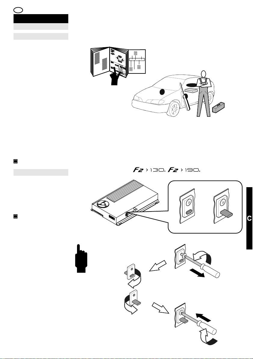
I
INSTALLAZIONE E
COLLEGAMENTI
REGOLE GENERALIMAIN TIPSREGLES GENERALES
Tipologie di impiantoSystem types
Per facilitare le
operazioni di
collegamento e di
regolazione
dell’amplificatore,
vengono rappresentate
di seguito alcune
tipologie di impianto, con
i collegamenti degli
ingressi, delle uscite e le
relative regolazioni.
Ciò non vieta
all’installatore di
personalizzare
ulteriormente il sistema e
di utilizzare più di
un’amplificatore nella
realizzazione del sistema
audio, purché ogni
operazione venga
condotta in accordo con
il Manuale d’uso.
48,50,52
Selezione del filtroFilter selectionSelection de filtre
Nei modelli F2>130 ed
F2>190, è possibile
selezionare il tipo di filtro
crossover tra Passa-alto
e Passa-basso ruotando
la chiavetta plastica nera
sul Pannello Comandi.
34,50,60
LPHP
Per effettuare il cambio
tipo, svitare la vite di
fissaggio, ruotare la
chiavetta disponendo la
protuberanza all’interno
per il tipo Passa-alto o
all’esterno per il tipo
Passa-basso, riavvitare
la vite di fissaggio.
45
Page 46

E D F GB
INSTALACIÓN Y
CONEXIONES
REGLAS GENERALES
Impedancia de la carga en
salida
Es posible conectar
sistemas compuestos
por más altavoces,
siempre que la
impedancia total no sea
inferior a 2 Ohm en
configuración estéreo o
a 4 Ohm en
configuración mono
puenteado.
Es admisible bajar
hasta 2 Ohm en mono
puenteado si se utilizan
Subwoofers filtrados
adecuadamente. En la
modalidad trimode, las
impedancias totales de
los sistemas tanto en
estéreo como en mono
no deben ser inferiores
a 4 Ohm.
Filtros pasivos
Por norma general, en
la realización de
sistemas TRIMODE es
necesario optimizar la
respuesta de los
distintos altavoces
haciendo uso de filtros
pasivos realizados con
condensadores e
inductores de audio. Al
lado figura una tabla útil
para determinar los
valores de los
componentes
necesarios: L para los
inductores, C para los
condensadores. Si se
utilizan altavoces con
impedancia de 8 ohm,
el valor de los
inductores se dobla
mientras que el de los
condensadores se
divide por la mitad.
INSTALLATION UND
ANSCHLÜSSE
ALLGEMEINE REGELN
Impedanz Ausgangslast
Es ist möglich, Systeme
mit mehreren
Lautsprechern
anzuschließen,
vorausgesetzt, die
Gesamtimpedanz weist
mindestens einen Wert
von 2 Ohm bei
stereofoner Konfiguration
oder 4 Ohm bei
monofoner, überbrückter
Konfiguration auf.
Sie können bei der
monofonen, überbrückten
Konfiguration einen Wert
von bis zu 2 Ohm wählen,
wenn zweckmäßig
gefilterte Subwoofer
verwendet werden.
Im Modus Trimode darf
die Gesamtimpedanz der
Systeme (stereofon und
monofon) nicht weniger
als 4 Ohm betragen.
Passive Filter
Normalerweise ist es
bei Systemen
TRIMODE erforderlich,
das Antwortsignal der
verschiedenen
Lautsprecher zu
optimieren, indem
passive Filter mit
Kondensatoren und
Induktoren zur
Audiobenutzung
verwendet werden.
Nebenstehend ist eine
Tabelle abgebildet, die
Ihnen hilft, die Werte
der notwendigen
Komponenten zu
finden: L für Induktoren
C für Kondensatoren.
Verwenden Sie
Lautsprecher mit einer
Impedanz von 8 Ohm,
verdoppelt sich der
Wert der Induktoren,
während sich derjenige
der Kondensatoren um
die Hälfte verringert.
INSTALLATION ET
CONNEXIONS
Impédance de la charge en
sortie
Il est possible de
raccorder des systèmes
composés de plusieurs
haut-parleurs, à
condition que
l'impédance totale ne
soit pas inférieure à 2
ohms en configuration
Stéréophonique ou à 4
ohms en configuration
Mono à pont.
Il est possible de
descendre jusqu'à 2
ohms en Mono à pont
si l'on pilote des
caissons de grave
filtrés comme il se doit.
En mode Trimode, les
impédances globales
des systèmes
Stéréophonique et
Monophonique ne
doivent pas être
inférieures à 4 ohms.
Habituellement, dans la
réalisation des
systèmes TRIMODE, il
est nécessaire
d'optimiser la réponse
des différents hautparleurs en utilisant des
filtres passifs réalisés
avec des
condensateurs et des
inducteurs pour audio.
Le tableau présenté cicontre permet de
trouver facilement les
valeurs des
composants
nécessaires : L pour les
Inducteurs C pour les
condensateurs. Si l'on
utilise des haut-parleurs
ayant une impédance
de 8 ohms, la valeur
des inducteurs
redouble, tandis que
celle des
condensateurs est
réduite de moitié.
46
INSTALLATION AND
CONNECTIONS
Output load impedance
Systems composed of
several loudspeakers
can be connected, as
long as the overall
impedance is not less
than 2 Ohm in Stereo
configuration or 4 Ohm
in bridge Mono
configuration.
You may drop to 2 Ohm
in bridge Mono if
suitably filtered
Subwoofers are piloted.
In Trimode mode, the
overall impedances of
both the Stereo and
Mono systems should
not be less than 4
Ohm.
Passive crossoversFiltres passifs
Normally, when building
TRIMODE systems, it is
necessary to optimise
the response of the
various loudspeakers,
using Passive Filters
fitted with Capacitors
and Inductors for audio
use. Opposite is a table
to help you identify the
values of the
components required: L
for Inductors and C for
Capacitors. If
loudspeakers with an
impedance of 8 Ohm
are used, the value of
the Inductors is
doubled, while that of
the capacitors is
halved.
Page 47
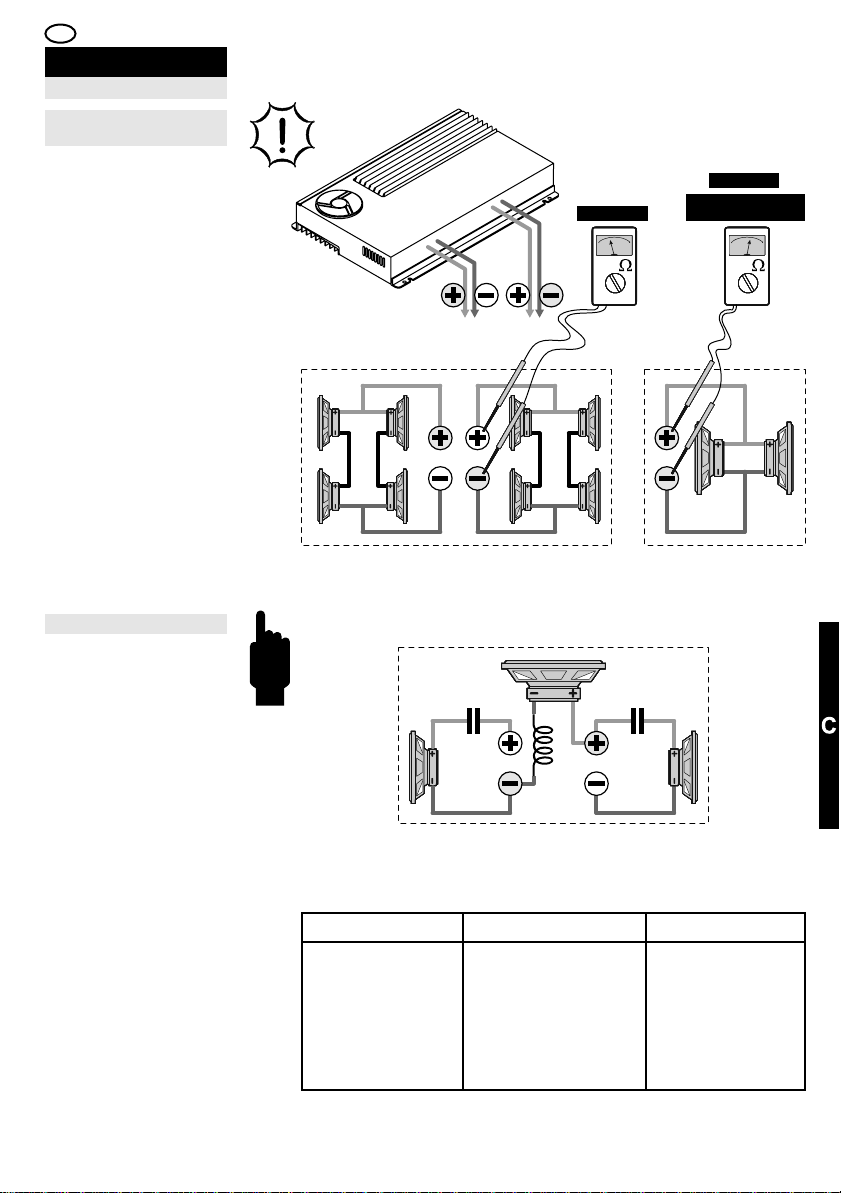
I
INSTALLAZIONE E
COLLEGAMENTI
REGOLE GENERALIMAIN TIPSREGLES GENERAL
Impedenza del carico in
uscita
E’ possibile collegare
sistemi composti da più
altoparlanti, purché
l’impedenza
complessiva non sia
inferiore a 2 Ohm in
configurazione
Stereofonica o a 4 Ohm
in configurazione Mono
a ponte.
E’ ammesso scendere
fino a 2 Ohm in Mono a
ponte, se si pilotano
Subwoofers
opportunamente filtrati.
Nella modalità Trimode,
le impedenze
complessive sia dei
sistemi Stereofonico
che Monofonico non
devono essere inferiori
a 4 Ohm.
STEREO
2 OHM MIN.
4 OHM MIN.
2 OHM MIN. SUB +
LP CROSSOVER ON
BRIDGED MONO
Filtri passivi
Di norma, nella
realizzazione di sistemi
TRIMODE è necessario
ottimizzare la risposta
dei vari altoparlanti
adoperando Filtri
Passivi realizzati con
Condensatori ed
Induttori per uso audio.
A fianco è riportata una
tabella utile ad
individuare i valori dei
componenti necessari:
L per gli Induttori C per
i condensatori. Se si
utilizzano altoparlanti
con impedenza di 8
Ohm il valore degli
Induttori raddoppia
mentre quello dei
condensatori dimezza.
Crossover f (Hz)
80
100
130
150
200
260
C C
L
TRIMODE
L Inductance (mH)
8
6,4
4,9
4,25
3,2
2,45
C Capacitor (µF)
500
400
300
270
200
150
47
Page 48

E D F GB
INSTALACIÓN Y
CONEXIONES
EJEMPLOS DE
CONFIGURACIÓN
STEREO
Frente Anterior.
INSTALLATION UND
ANSCHLÜSSE
KONFIGURATIONS
BEISPIELE
STEREO
Vorderfront.
INSTALLATION ET
CONNEXIONS
EXEMPLES
CONFIGURATIONS
STEREO
INSTALLATION AND
CONNECTIONS
CONFIGURATION
SUGGESTIONS
STEREO
Front Stage.Front antérieur. Fronte Anteriore.
(F2>130 / F2>190)
Conexión de la señal
de entrada y ajustes.
(F2>300 / F2>500)
Conexión de la señal
de entrada y ajustes.
48
(F2>130 / F2>190)
Anschluss des
Eingangssignals und
Einstellungen.
(F2>300 / F2>500)
Anschluss des
Eingangssignals und
Einstellungen.
(F2>130 / F2>190)
Connexion du signal
d'entrée et réglages.
(F2>300 / F2>500)
Connexion du signal
d'entrée et réglages.
(F2>130 / F2>190)
Connection of the input
signal and adjustments.
(F2>300 / F2>500)
Connection of the input
signal and adjustments.
Page 49

I
INSTALLAZIONE E
COLLEGAMENTI
CONFIGURAZIONI
D’ESEMPIO
STEREO
LEFT RIGHT
(F2>130 / F2>190)
Collegamento del
segnale d’ingresso e
regolazioni.
(F2>300 / F2>500)
Collegamento del
segnale d’ingresso e
regolazioni.
l/ r
r
/l
L
R
L
R
49
Page 50

E D F GB
INSTALACIÓN Y
CONEXIONES
EJEMPLOS DE
CONFIGURACIÓN
MONO
Subwoofer con filtro
Pasa-bajo.
INSTALLATION UND
ANSCHLÜSSE
KONFIGURATIONS
BEISPIELE
MONO
Subwoofer mit Filter
Tiefpass
INSTALLATION ET
CONNEXIONS
EXEMPLES
CONFIGURATIONS
Subwoofer avec filtre
Passe-Bas.
INSTALLATION AND
CONNECTIONS
CONFIGURATION
SUGGESTIONS
MONOMONO
Subwoofer with LowPass filter.
(F2>130 / F2>190)
Conexión de la señal
de entrada mono y
ajustes.
(F2>300 / F2>500)
Conexión de la señal
de entrada mono y
ajustes.
50
(F2>130 / F2>190)
Anschluss des
monofonen
Eingangssignals und
Einstellungen.
(F2>300 / F2>500)
Anschluss des
monofonen
Eingangssignals und
Einstellungen.
(F2>130 / F2>190)
Connexion du signal
d'entrée Monophonique
et réglages.
(F2>300 / F2>500)
Connexion du signal
d'entrée Monophonique
et réglages.
(F2>130 / F2>190)
Connection of the
Monophonic input
signal and adjustments.
(F2>300 / F2>500)
Connection of the
Monophonic input
signal and adjustments.
Page 51

I
INSTALLAZIONE E
COLLEGAMENTI
CONFIGURAZIONI
D’ESEMPIO
MONO
Subwoofer con filtro
Passa-basso.
SUB
(F2>130 / F2>190)
Collegamento del
segnale d’ingresso
Monofonico e
regolazioni.
(F2>300 / F2>500)
Collegamento del
segnale d’ingresso
Monofonico e
regolazioni.
MONO OUTPUTMONO OUTPUT
MONO OUTPUTMONO OUTPUT
off
lp
mono
on
mono
on
51
Page 52

E D F GB
INSTALACIÓN Y
CONEXIONES
EJEMPLOS DE
CONFIGURACIÓN
TRIMODE
Frente Anterior y
Subwoofer.
INSTALLATION UND
ANSCHLÜSSE
KONFIGURATIONS
BEISPIELE
TRIMODE
Vorderfront und
Subwoofer
INSTALLATION ET
CONNEXIONS
EXEMPLES
CONFIGURATIONS
TRIMODE
Subwoofer avec filtre
Passe-Bas.
INSTALLATION AND
CONNECTIONS
CONFIGURATION
SUGGESTIONS
TRIMODE
Front Stage and
Subwoofer.
(F2>130 / F2>190)
Conexión de la señal
de entrada y ajustes.
(F2>300 / F2>500)
Conexión de la señal
de entrada y ajustes.
52
(F2>130 / F2>190)
Anschluss des
Eingangssignals und
Einstellungen.
(F2>300 / F2>500)
Anschluss des
Eingangssignals und
Einstellungen.
(F2>130 / F2>190)
Connexion du signal
d'entrée et réglages.
(F2>300 / F2>500)
Connexion du signal
d'entrée et réglages.
(F2>130 / F2>190)
Connection of the input
signal and adjustments.
(F2>300 / F2>500)
Connection of the input
signal and adjustments.
Page 53
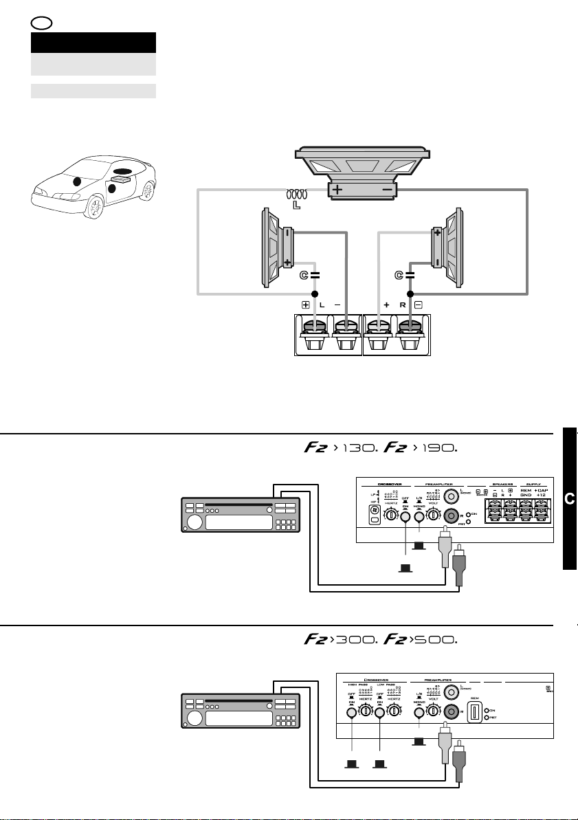
I
INSTALLAZIONE E
COLLEGAMENTI
CONFIGURAZIONI
D’ESEMPIO
TRIMODE
Fronte Anteriore e
Subwoofer.
SUB
LEFT RIGHT
(F2>130 / F2>190)
Collegamento del
segnale d’ingresso e
regolazioni.
(F2>300 / F2>500)
Collegamento del
segnale d’ingresso e
regolazioni.
off off
off
l/r
r
/l
L
R
L
R
53
Page 54

E D F GB
INSTALACIÓN Y
CONEXIONES
INSTALLATION UND
ANSCHLÜSSE
STROMVERSORGUNGALIMENTACIÓN
INSTALLATION ET
CONNEXIONS
INSTALLATION AND
CONNECTIONS
POSITIVO
Conectar el terminal
positivo "+12V" (20) al
polo positivo de la
batería pasando por un
fusible de seguridad
externo (no
suministrado).
42
NEGATIVO
Conectar firmemente el
terminal "GND" (18) a
un punto metálico del
vehículo bien limpio de
residuos, utilizando un
cable lo más corto
posible.
42
ENCENDIDO REMOTO
Conectar el terminal de
encendido remoto
(+12V) de la fuente al
terminal "REM" (17)
del amplificador,
utilizando un cable con
una terminación
adecuada.
42
POSITIVANSCHLUSS
Verbinden Sie die
Klemme „+12V“ (20)
über eine externe
Schmelzsicherung
(nicht mitgeliefert) mit
dem Pluspol der
Batterie.
42
NEGATIVANSCHLUSS
Schließen Sie die
Klemme „GND“ (18)
solide an eine
metallene,
rückstandsfreie Stelle
des Fahrzeugs an. Das
hierzu verwendete
Kabel sollte so kurz wie
möglich sein..
42
FERNEINSCHALTUNG
Verbinden Sie den
Anschluss der Quelle
für die Ferneinschaltung
(+12V) mit der
Verstärkerklemme
„REM” (17), verwenden
Sie hierzu bitte ein
Kabel mit
fachgerechtem
Kabelabschluss.
42
POSITIF
Raccorder la borne
“+12V“ (20) au pôle
Positif de la batterie en
passant par un fusible
de sécurité externe
(Non fourni).
42
NÉGATIF
Raccorder fermement
la borne « GND » (18) à
un point métallique de
la voiture dont l'on aura
éliminé tous les résidus
et ou traces de
peinture. Utiliser un
câble le plus court
possible.
42
ALLUMAGE À
DISTANCE
Raccorder la borne
d'allumage à distance
(+12V) de la source à la
borne “REM” (17) de
l'amplificateur, en
utilisant un fil dont l'on
préparera l'extrémité
comme il se doit.
42
POSITIVE
Connect the “+12V“
(20) terminal to the
Positive pole of the
battery via an external
safety fuse (not
supplied).
42
NEGATIVE
Connect the “GND“
terminal (18) firmly to a
metal part of the vehicle
free from any residue,
using the shortest
possible cable
42
REMOTE SWITCH-ON
Connect the remote
(+12V) switch-on
terminal of the Source
to the “REM” (17)
terminal on the
amplifier, using a wire
with a suitable fitting.
42
CONDENSADORES DE
ALIMENTACIÓN.
¡SEGUIR LAS
INDICACIONES DEL
FABRICANTE PARA LA
CONEXIÓN!
SE DECLINA TODA
RESPONSABILIDAD
DERIVADA DEL USO
INADECUADO DE
DISPOSITIVOS DE
ALIMENTACIÓN
EXTERNOS
KONDENSATOREN ZUR
STROMVERSORGUNG:
HALTEN SIE SICH
HINSICHTLICH DER
ANSCHLÜSSE BITTE
AN DIE ANGABEN DES
HERSTELLERS!
WIR HAFTEN NICHT FÜR
SCHÄDEN, DIE DURCH
UNSACHGEMÄSSEN
GEBRAUCH EXTERNER
STROMVERSOR-GUNGS
VERURSACHT WERDEN.
DEN
SYSTEME
CONDENSATEURS
D'ALIMENTATION.
EFFECTUER LA
CONNEXION EN
SUIVANT LES
INDICATIONS DU
CONSTRUCTEUR!
NOUS DÉCLINONS
TOUTE
RESPONSABILITÉ EN
CAS D'UTILISATION
IMPROPRE DES
DISPOSITIFS
D'ALIMENTATION
EXTERNES.
POWER SUPPLY
CAPACITOR.
FOLLOW THE
MANUFACTURER'S
INSTRUCTIONS FOR
THE CONNECTION!
THE MANUFACTURER
WILL NOT BE HELD
LIABLE IN THE EVENT
OF INAPPROPRIATE
USE OF EXTERNAL
POWER SUPPLY
DEVICES
54 55
Page 55

I
INSTALLAZIONE E
COLLEGAMENTI
ALIMENTAZIONEPOWER SUPPLYALIMENTATION
POSITIVO
Collegare il morsetto
“+12V“ (20) al polo
Positivo della batteria
passando per un
fusibile di sicurezza
esterno (Non fornito).
42
NEGATIVO
Collegare saldamente il
morsetto “GND“ (18) ad
un punto metallico della
vettura ripulito da
residui, utilizzando un
cavo il più corto
possibile.
42
ACCENSIONE
REMOTA
Collegare il terminale di
accensione remota
(+12V) della Sorgente
al morsetto “REM” (17)
dell’amplificatore,
utilizzando un cavetto
opportunamente
terminato.
42
CONDENSATORI DI
ALIMENTAZIONE.
SEGUIRE LE
INDICAZIONI DEL
COSTRUTTORE PER IL
COLLEGAMENTO!
SI DECLINA OGNI
RESPONSABILITÀ
DERIVATA DALL’USO
IMPROPRIO DI
DISPOSITIVI DI
ALIMENTAZIONE
ESTERNI
Page 56
E D F GB
AJUSTE Y
UTILIZACIÓN
REGULIERUNG UND
GEBRAUCH
UTILISATION
ADJUSTMENTS AND USERÉGLAGES ET
Primera utilización
Antes de conectar los
terminales a la batería,
asegurarse de que
todas las conexiones se
hayan efectuado según
este manual de uso con
la documentación
correspondiente de los
dispositivos conectados
al amplificador.
Comprobar que todas
las operaciones de
instalación respetan
los REQUISITOS DE
SEGURIDAD. Reducir
el volumen al mínimo
y encender la fuente.
Lectura de los testigos de
funcionamiento
“STATUS"
Las combinaciones a,
b, c, d de los testigos
de funcionamiento
verde "ON" y rojo “PRT"
indican el estado
operativo del
amplificador:
38,64,66,68
a - Amplificador
apagado.
b - Amplificador
encendido.
c - Amplificador en
estado de suspensión
(Muting) o protección.
d - Amplificador
averiado.
CONSULTAR LA
PARTE DE LA
SECCIÓN
“ANOMALÍAS Y
SOLUCIONES” PARA
INFORMACIÓN
ADICIONAL
56
Erste Inbetriebnahme
Bevor Sie die Klemmen
an die Batterie
anschließen, versichern
Sie sich bitte, dass jede
Verbindung gemäß den
Anweisungen dieses
Benutzerhandbuchs und
der entsprechenden
Dokumentation der an
den Verstärker
angeschlossenen
Vorrichtungen
vorgenommen wurde.
Prüfen Sie, ob alle
Installationsvorgänge
den
SICHERHEITSVORSCHRIFTEN
entsprechen.
Reduzieren Sie die
Lautstärke auf das
Minimum und schalten
Sie die Quelle ein.
Signalisierungen der
Betriebsanzeige-LEDs
“STATUS”
Die Kombinationen a,
b, c, d der
Betriebsanzeige-LEDs
Grün „ON” und Rot
„PRT” geben den
Betriebszustand des
Verstärkers wieder:
38,64,66,68
a - Verstärker
ausgeschaltet.
b - Verstärker
eingeschaltet.
c - Verstärker auf
Stummschaltung (Muting)
oder Schutzschaltung.
d - Störung im
Verstärker.
WEITERE
INFORMATIONEN
FINDEN SIE IN TEIL D
DES ABSCHNITTS
„STÖRUNGEN UND
STÖRUNGSBEHEBUNG“
Premiere utilization
Avant de raccorder les
bornes à la batterie,
s'assurer que toutes les
connexions ont été
effectuées
conformément aux
indications de ce
Manuel d'utilisation et
de toute la
documentation des
dispositifs raccordés à
l'amplificateur.
Veiller à ce que toutes
les opérations
d'installation soient
conformes aux
CONSIGNES DE
SÉCURITÉ.
Abaisser au minimum
le volume et allumer
la source.
fonctionnement
“STATUS“
Les combinaisons a, b,
c, d des voyants de
fonctionnement Vert
“ON” et Rouge “PRT”
indiquent l'état de
marche de
l'amplificateur :
38,64,66,68
a - Amplificateur éteint.
b - Amplificateur
allumé.
c - Amplificateur en
état de suspension
(Muting) ou protection.
d - Amplificateur
endommagè.
CONSULTER LA
PARTIE D
“ANOMALIES ET
SOLUTIONS” DU
MANUEL POUR
TOUTE INFORMATION
COMPLÉMENTAIRE
UTILE.
First usage
Before connecting the
terminals to the battery,
make sure that all
connections have been
made in accordance
with this User's Guide
and with the relevant
documentation for the
devices connected to
the amplifier.
Make sure that all the
installation operations
observe the SAFETY
PRECAUTIONS.
Set volume to
minimum and switchon the source.
Reading the indicator LEDsLecture des voyants de
“STATUS“
The combinations
a,b,c,d of the Green
“ON” and Red “PRT”
indicator LEDs indicate
the operating status of
the Amplifier:
38,64,66,68
a - Amplifier off.
b - Amplifier on.
c - Amplifier in muting
status or protection.
d - Amplifier in fault
status
CONSULT PART D
“TROUBLESHOOTING
” OF THE USER’S
GUIDE FOR FURTHER
DETAILS
Page 57
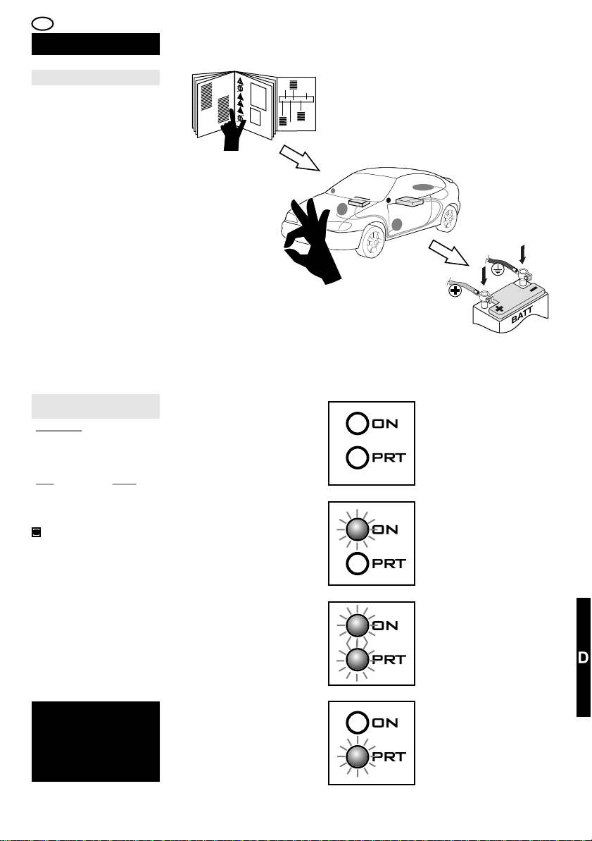
I
REGOLAZIONI ED
UTILIZZO
Primo utilizzo
Prima di collegare i
morsetti alla batteria,
accertarsi che ogni
collegamento sia stato
eseguito in accordo con
questo Manuale d’uso e
con la relativa
documentazione dei
dispositivi collegati
all’amplificatore.
Verificare che tutte le
operazioni di
installazione
rispettino le
PRESCRIZIONI DI
SICUREZZA.
Ridurre il volume al
minimo ed accendere
la sorgente.
Lettura delle spie di
funzionamento
“STATUS“
Le combinazioni a,b,c,d
delle spie di
funzionamento Verde
“ON” e Rossa “PRT”
indicano lo stato
operativo
dell’Amplificatore:
38,64,66,68
a - Amplificatore
spento.
b - Amplificatore
acceso.
c - Amplificatore in
stato di sospensione
(Muting) o protezione.
d - Amplificatore in
avaria.
CONSULTARE LA
PARTE D ALLA
SEZIONE “ANOMALIE
E RIMEDI” PER
ULTERIORI
INFORMAZIONI
a
b
c
d
57
Page 58

E D F GB
AJUSTE Y
UTILIZACIÓN
Regulación de la sensibilidad Einstellung der Empfindlichkeit
Con un destornillador
plano, girar en sentido
contrario al movimiento
de las agujas del reloj
el potenciómetro de la
sensibilidad (9) hasta el
final del recorrido.
REGULIERUNG UND
GEBRAUCH
Drehen Sie mit einem
flachen
Schraubenzieher das
Potenziometer für die
Empfangsempfindlichkeit (9) bis zum
Endanschlag nach
UTILISATION
À l'aide d'un tournevis à
tête plate, tourner dans
le sens contraire des
aiguilles d'une montre
les potentiomètres pour
la sensibilité (9),
jusqu'en fin de course.
links.
Bajar al mínimo el
volumen de la fuente.
Stellen Sie die
Abaisser au minimum le
volume de la source.
Lautstärke der Quelle
Encender la fuente.
auf das Minimum.
Allumer la source.
ADJUSTMENTS AND USERÉGLAGES ET
Using a flat-tip
screwdriver, turn the
potentiometers anticlockwise for the
sensitivity (9), until you
reach the end of the
range..
Turn the volume of the
Source down to the
minimum.
Poner el volumen del
autorradio a 3/4 de su
recorrido.
Girar en sentido del
movimiento de las
agujas del reloj el
potenciómetro de la
sensibilidad (9) hasta
notar las primeras
señales de distorsión
del sonido.
36
Schalten Sie die Quelle
ein.
Stellen Sie die
Lautstärke des
Autoradios auf 75 %
der Leistung.
Drehen Sie das
Potenziometer für die
Empfindlichkeit (9) im
Uhrzeigersinn, bis Sie
die ersten Anzeichen
einer Tonverzerrung
wahrnehmen.
36
Positionner le volume
de l'autoradio aux 3/4
de sa course.
Tourner dans le sens
des aiguilles d'une
montre le potentiomètre
de la sensibilité (9)
jusqu'à ce que l'on
entende les premiers
signes de distorsion du
son.
36
Turn on the Source.
Position the car radio
volume to 3/4 of its
range.
Turn the sensitivity
potentiometer (9)
clockwise until you hear
the first signs of sound
distortion.
36
58
Page 59

I
REGOLAZIONI ED
UTILIZZO
Regolazione della sensibilitàSensitivity adjustmentRéglage de la sensibilité
Con un cacciavite a
taglio, ruotare in senso
antiorario il
potenziometro della
sensibilità (9), fino alla
fine della corsa.
Abbassare al minimo il
volume della Sorgente.
Accendere la Sorgente.
Posizionare il volume
dell’autoradio a 3/4
della sua corsa.
Ruotare in senso orario
il potenziometro della
sensibilità (9) fino ad
avvertire i primi cenni di
distorsione sul suono.
36
MIN.
3/4
9
VOL
ON
VOL
9
59
Page 60

E D F GB
AJUSTE Y
UTILIZACIÓN
REGULIERUNG UND
GEBRAUCH
UTILISATION
ADJUSTMENTS AND USERÉGLAGES ET
Regulación del crossover
Si la configuración
elegida prevé la
utilización de crossover,
es necesario:
Activarlos con el
selector (3) para
F2>130 y F2>190, con
los selectores (4)
HP y/o (6) LP para
F2>300 y F2>500.
34,36,50,52
Sólo para F2>130 y
F2>190, ajustar el tipo
de filtro en Pasa-bajo
LP o Pasa-alto HP
girando la clavija de
plástico (1).
34,44,50
Regular la frecuencia
de trabajo actuando
sobre los
potenciómetros (2) para
F2>130 y F2>190, (5)
y/o (7) para F2>300 y
F2>500, ajustando el
punto en el que el
crossover efectúa la
“limitación” de la banda
de salida.
34,36,50
En función de las
especificaciones
técnicas de los
altavoces conectados,
girar con un
destornillador plano los
potenciómetros
correspondientes hasta
ajustar la frecuencia
deseada.
Regulierung des Crossover
Sieht die Konfiguration
den Gebrauch von
Crossover-Filtern vor,
ist es erforderlich:
Diese für F2>130 und
F2>190 über den
Wählschalter (3) und für
F2>300 und F2>500
über die Wählschalter
(4) HP und/oder (6) LP
zu aktivieren.
34,36,50,52
Stellen Sie nur bei den
Modellen F2>130 und
F2>190 den Filtertyp
entweder auf Hochpass
HP oder Tiefpass TP
ein, indem Sie den
kleinen Plastikschlüssel
(1) drehen.
34,44,50
Regulieren Sie die
Interventionsfrequenz
bei den Modellen
F2>130 und F2>190
über die Potenziometer
(2) und bei den
Modellen F2>300 und
F2>500 über (5)
und/oder (7). Stellen
Sie den Punkt ein, ab
dem der Crossover das
Ausgangsfrequenzband
„einschränken“ soll.
34,36,50
Drehen Sie je nach den
technischen
Eigenschaften der
angeschlossenen
Lautsprecher die
entsprechenden
Potenziometer mit
einem flachen
Schraubenzieher, bis
Sie die gewünschte
Frequenz erzielt haben.
Réglage du répartiteur
Si la configuration
choisie prévoit l'emploi
de répartiteurs, il est
nécessaire de:
Les activer avec le
sélecteur (3) pour
F2>130 et F2>190,
avec les sélecteurs (4)
HP et/ou (6) LP pour
F2>300 et F2>500.
34,36,50,52
Pour F2>130 et
F2>190, régler le type
de filtre en Passe-bas
LP ou Passe-haut HP
en tournant la petite clé
en plastique (1).
34,44,50
Régler la fréquence
d'intervention en
agissant sur les
potentiomètres (2) pour
F2>130 et F2>190, (5)
et/ou (7) pour F2>300
et F2>500, en réglant le
point où le répartiteur
effectue la « limitation »
de la bande en sortie.
34,36,50
En fonction des
spécifications
techniques des hautparleurs raccordés,
tourner les
potentiomètres avec un
tournevis à tête plate
jusqu'à ce que l'on
centre la fréquence
désirée.
Crossover adjustment
If the chosen
configuration foresees
the use of the
crossovers, necessary
you must:
Activate them via knob
(3) for F2>130 and
F2>190, via knobs (4)
HP and/or (6) LP for
F2>300 and F2>500.
34,36,50,52
Only for F2>130 and
F2>190, set the type of
filter to low-pass LP or
high-pass HP by turning
the black plastic key
(1).
34,44,50
Adjust the intervention
frequency on the
potentiometers (2) for
F2>130 and F2>190,
(5) and/or (7) for
F2>300 and F2>500,
setting the point at
which the crossover
performs the “limitation”
of the output band.
34,36,50
Depending on the
technical characteristics
of the loudspeakers
connected, turn the
relevant potentiometers
using a flat-tip
screwdriver, until you
obtain the desired
frequency.
60
Page 61
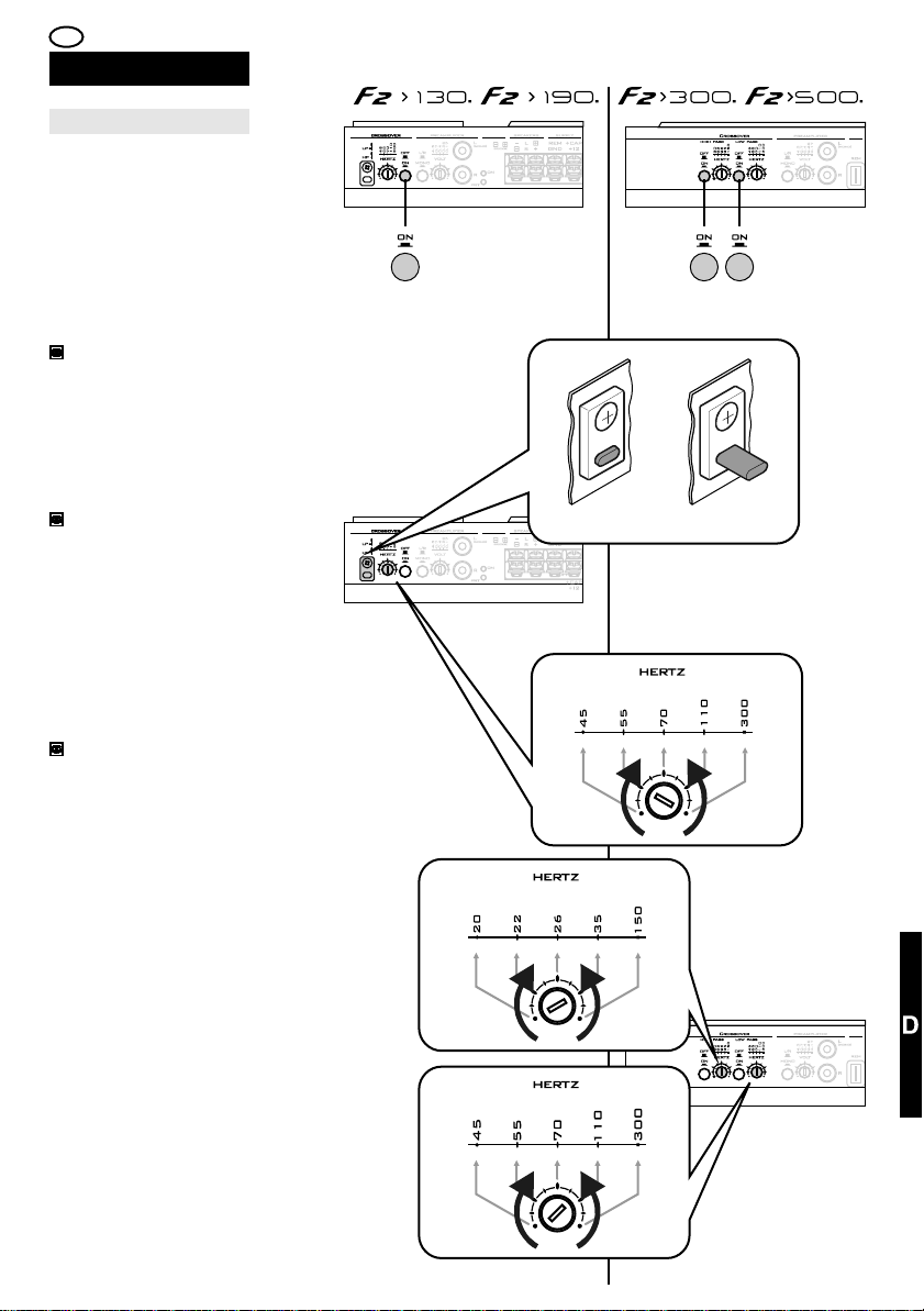
I
REGOLAZIONI ED
UTILIZZO
Regolazione del crossover
Se la configurazione
scelta prevede l’utilizzo
dei crossover, è
necessario:
Attivarli con il selettore
(3) per F2>130 e
F2>190, con i selettori
(4) HP e/o (6) LP per
F2>300 e F2>500.
34,36,50,52
Solo per F2>130 e
F2>190, impostare il
tipo di filtro in Passabasso LP o Passa-alto
HP ruotanto la chiavetta
plastica (1).
34,44,50
Regolare la frequenza
di intervento agendo sui
potenziometri (2) per
F2>130 e F2>190, (5)
e/o (7) per F2>300 e
F2>500, impostando il
punto in cui il crossover
effettua la “limitazione”
della banda in uscita.
34,36,50
3 4 6
HP LP
1
LPHP
2
In base alle specifiche
tecniche degli
altoparlanti collegati,
ruotare con un
cacciavite a taglio i
potenziometri opportuni
fino a centrare la
frequenza desiderata.
5
7
61
Page 62

E D F GB
AJUSTE Y
UTILIZACIÓN
Mantenimiento
REGULIERUNG UND
GEBRAUCH
Wartung
UTILISATION
Entretien Maintenance
ADJUSTMENTS AND USERÉGLAGES ET
Para cualquier
operación de
mantenimiento
extraordinaria, acuda al
distribuidor (punto de
venta).
VENTILADOR
Comprobar de vez en
cuando que el
ventilador de
refrigeración gira
libremente. En caso
necesario, limpiar con
un cepillo.
LIMPIEZA
Efectuar las
operaciones de
limpieza usando un
cepillo con cerdas
blandas y un trapo
ligeramente húmedo.
No usar detergentes.
Prestar atención a no
cambiar los ajustes de
los selectores y los
ajustes del Panel de
Control.
Wenden Sie sich für
jeden
außergewöhnlichen
Wartungseingriff bitte
an Ihren Händler.
LÜFTER
Prüfen Sie regelmäßig,
ob der
Lüftungsventilator frei
drehen kann.
Reinigen Sie diesen
gegebenenfalls mit
einem Pinsel.
REINIGUNG
Nehmen Sie die
Reinigung mit einem
weichen Pinsel und
einem leicht
angefeuchteten Tuch
vor.
Benutzen Sie keine
Reinigungsmittel.
Achten Sie darauf, die
Position der
Wählschalter und die
Regulierungen an der
Steuerung nicht zu
verändern.
Pour toute opération
d'entretien
extraordinaire,
s'adresser au point de
vente.
VENTILATEUR
Contrôler de temps à
autre que le ventilateur
de refroidissement est
libre de tourner.
Éventuellement, le
nettoyer avec un
pinceau.
NETTOYAGE
Effectuer les opérations
de nettoyage en
utilisant un pinceau à
soies souples et un
chiffon légèrement
humide.
Ne pas utiliser de
détergents.
Veiller à ne pas
changer les réglages
des sélecteurs et les
réglages sur le
Panneau de
Commande.
For all unscheduled
maintenance work,
contact your Retailer.
FAN
Check periodically that
the cooling fan is free to
operate without
obstructions. If
necessary, clean it with
a paintbrush.
CLEANING
Perform the cleaning
operations using a soft
paintbrush and a
slightly damp cloth.
Do not use detergents.
Pay attention not to
inadvertently change
the knob settings and
adjustments on the
Control Panel while
cleaning.
SUSTITUCIÓN DEL
FUSIBLE
Proceder a la
sustitución del fusible
(21) asegurándose de
que la fuente esté
apagada. Quitar el
fusible quemado y
sustituirlo por uno del
mismo tipo y de
idénticas características
(misma intensidad
máxima).
22,42
62
ERSATZ DER
SICHERUNGEN
Ersetzen Sie die
Sicherungen (21) nur,
nachdem Sie sich
überzeugt haben, dass
die Quelle ausgeschaltet
ist.
Entfernen Sie die
durchgebrannte
Sicherung und ersetzen
Sie diese durch eine
andere Sicherung
desselben Typs und
derselben Leistung
(gleicher Maximalstrom).
22,42
REMPLACEMENT DU
FUSIBLE
Procéder au
remplacement du
fusible (21) en veillant
d'abord à ce que la
source soit éteinte.
Enlever le fusible grillé
et le remplacer par un
fusible du même type et
présentant une portée
égale (courant consenti
égal).
22,42
FUSE REPLACEMENT
Proceed with the fuse
replacement (21)
making sure you have
turned off the Source
beforehand.
Remove the burnt fuse
and replace it with a
new one of the same
type and capacity
(same maximum
current).
22,42
Page 63
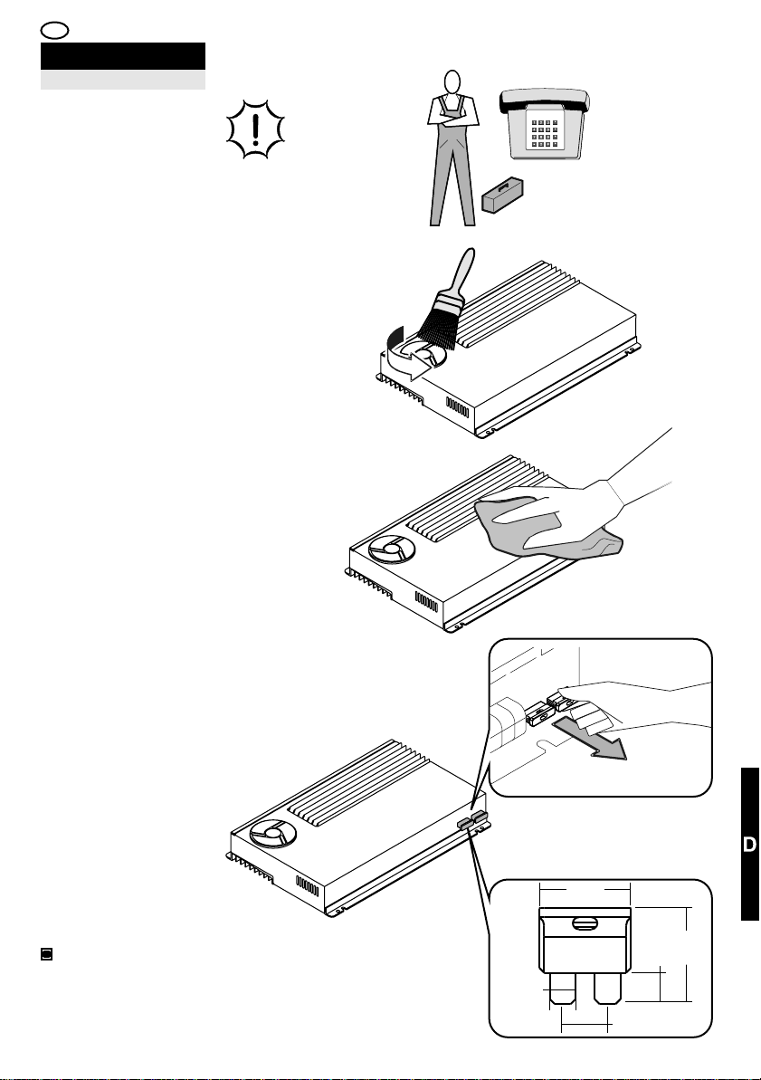
I
REGOLAZIONI ED
UTILIZZO
Manutenzione
Per qualsiasi
operazione di
manutenzione
straordinaria, rivolgersi
al Punto Vendita.
VENTOLA
Verificare di tanto in
tanto che la ventola di
raffreddamento sia
libera di ruotare.
Eventualmente ripulire
con un pennello.
PULIZIA
Effettuare le operazioni
di pulizia usando un
pennello a setole
morbide ed uno straccio
leggermente inumidito.
Non usare detergenti.
Fare attenzione a non
cambiare le
impostazioni dei
selettori e le
regolazione sul
Pannello di Comando.
SOSTITUZIONE DEL
FUSIBILE
Procedere alla
sostituzione del fusibile
(21) assicurandosi che
la Sorgente sia spenta.
Togliere il fusibile
bruciato e sostituirlo
con uno dello stesso
tipo e di pari portata
(stessa corrente
massima).
22,42
21
5,3mm
19mm
9,2mm
20mm
6,5mm
63
Page 64

E D F
AJUSTE Y UTILIZACIÓN
Anomalías y soluciones
TODAS LOS ARREGLOS
DEBEN LLEVARLOS A CABO
EXCLUSIVAMENTE PERSONAL
CUALIFICADO QUE DEBE
HABER LEÍDO Y
COMPRENDIDO EL MANUAL
DE USO.
REGULIERUNG UND GEBRAUCH
Störungen und Störungsbehebung
DIESE EINGRIFFE DÜRFEN
NUR VON QUALIFIZIERTEM
PERSONAL VORGENOMMEN
WERDEN, DAS VORLIEGENDES
BENUTZERHANDBUCH
GELESEN UND VERSTANDEN
HAT.
RÉGLAGES ET UTILISATION
Anomalies et solutions
CHAQUE ACTION DE
RÉPARATION DOIT ÊTRE
EXÉCUTÉE EXCLUSIVEMENT
PAR DU PERSONNEL QUALIFIÉ
QUI DEVRA AVOIR LU ET
ASSIMILÉ LE MANUEL
D'UTILISATION.
Fuente encendida, ausencia de
sonido, Led "ON" apaga-do,
Led "PRT" apagado.
CAUSA:
1. No hay tensión en el terminal
"REM".
2. El circuito de masa es
inadecuado.
SOLUCIÓN:
1. Comprobar y restablecer la
conexión de encendido a
distancia.
2. Comprobar y reponer el cable
y la solidez de las conexiones.
Fuente encendida, ausencia de
sonido, Led "ON"apagado, Led
"PRT" encendido.
CAUSA:
1. El circuito de alimentación
positiva es inadecuado.
2. El fusible(s) interno(s) y/o
externo(s) está/están
quemado(s).
3. La tensión presente en los
terminales de alimentación del
amplificador es inferior a 7
V DC.
4. El amplificador ha sufrido un
daño y la protección se ha
activado de modo irreversible.
SOLUCIÓN:
1. Comprobar y reponer el cable
y la solidez de los contactos en
el circuito de alimentación
positiva.
2. Sustituir el/los fusible(s) con
los correspondientes de tipo y
valor idéntico.
3. Recargar la batería y
verificar/restablecer el circuito de
alimentación.
4. Dirigirse al distribuidor (punto
de venta) para activar la
prestación del Servicio Técnico.
64
Quelle eingeschaltet, kein Ton,
LED „ON” ausgeschaltet, LED
„PRT” ausgeschaltet.
URSACHE:
1. Die Klemme „REM” steht nicht
unter Spannung.
2. Unkorrekter Erdungskreis.
BEHEBUNG:
1. Prüfen/Wiederherstellen des
Anschlusses der
Ferneinschaltung.
2. Prüfung des Verbindungskabels
und der Solidität der
Verbindungen.
Stromquelle eingeschaltet, kein
Ton, LED „ON” ausgeschaltet,
LED „PRT” eingeschaltet.
URSACHE:
1. Unkorrekter positiver
Versorgungsstromkreis.
2. Einzelne oder mehrere interne
und/oder externe Sicherungen
sind durchgebrannt.
3. Die Spannung an den
Klemmen der
Verstärkerversorgung ist geringer
als 7 V DC.
4. Am Verstärker sind Störungen
aufgetreten und der Schutz wurde
unwiderruflich aktiviert.
BEHEBUNG:
1. Prüfung des Kabels und der
Solidität der Kontakte am positiven
Versorgungsstromkreis.
2. Ersatz der Sicherungen durch
Sicherungen derselben Art und
Kapazität.
3. Aufladen der Batterie.
Prüfung/Wiederherstellung des
Versorgungsstromkreises.
4. Wenden Sie sich bitte an Ihren
Händler, um den Technischen
Kundendienst nutzen zu können.
Source allumée, absence du
son, Led “ON” éteinte, Led
“PRT” éteinte.
CAUSE :
1. Il n'y a pas de tension sur la
borne “REM”.
2. Le circuit de masse n'est pas
approprié.
SOLUTION :
1. Contrôler et rétablir la
connexion d'allumage à
distance.
2. Contrôler et rétablir le câble
et la solidité des connexions.
Source allumée, absence de
son, Led “ON” éteinte, Led
“PRT” allumée.
CAUSE :
1. Le circuit d'alimentation
positive n'est pas approprié.
2. Les fusibles interne et/ou
externe est/sont grillé/s.
3. La tension présente sur les
bornes d'alimentation de
l'amplificateur est inférieure à 7
VDC.
4. L'amplificateur a subi une
panne et la protection s'est
activée d'une manière
irréversible.
SOLUTION :
1. Contrôler et rétablir le câble
et la solidité des contacts dans
le circuit d'alimentation positive.
2. Remplacer le/les fusible/s
avec des fusibles
correspondants par leur type et
leur valeur.
3. Recharger la batterie et
contrôler/rétablir le circuit
d'alimentation.
4. S'adresser au point de vente
pour entreprendre la procédure
d'assistance Technique.
Page 65
GB I
ADJUSTMENTS AND USE
ALL TROUBLESHOOTING
OPERATIONS SHOULD BE
CARRIED OUT BY A QUALIFIED
TECHNICIAN ONLY
WHO HAS READ AND
UNDERSTOOD THE USER'S
MANUAL IN FULL.
REGOLAZIONI ED UTILIZZO
Anomalie e rimediFaults and troubleshooting
OGNI AZIONE DI RIMEDIO
DEVE ESSERE ESEGUITA
ESCLUSIVAMENTE DA
PERSONALE QUALIFICATO
CHE DEVE AVER LETTO E
COMPRESO IL MANUALE
D’USO.
Source on, no sound, “ON”
LED off and “PRT” LED off.
FAULT:
1. There is no voltage on
the“REM” terminal.
2. The Ground circuit is
unsuitable.
REMEDY:
1. Check and reset the remote
switch-on connection.
2. Check and reset the cable
and the solidity of connections.
Source on, no sound, “ON”
LED off and “PRT” LED on.
FAULT:
1. The power supply circuit is
unsuitable.
2. The internal and/or external
fuse(s) is/are burnt.
3. The voltage at the power
supply terminals of the amplifier
is below 7 VDC.
4. The amplifier has
malfunctioned and the
protection has been irreversibly
activated.
REMEDY:
1. Check and reset the cable
and the solidity of contacts in the
positive power supply circuit.
2. Replace the fuse(s) with (a)
new one(s) of the same type
and value.
3. Recharge the battery and
check/reset the power supply
circuit.
4. Contact your retailer to
activate the Technical Service
procedure.
Sorgente accesa, assenza di
suono, Led “ON” spento Led
“PRT” spento.
CAUSA:
1. Non c’è tensione sul
morsetto “REM”.
2. Il circuito di massa è
inadeguato.
RIMEDIO:
1. Verificare e ripristinare il
collegamento di accensione a
distanza.
2. Verificare e ripristinare il
cavo e la solidità delle
connessioni.
Sorgente accesa, assenza di
suono, Led “ON” spento Led
“PRT” acceso.
CAUSA:
1. Il circuito di alimentazione
positiva è inadeguato.
2. I fusibili interno e/o esterno
è/sono bruciato/i.
3. La tensione presente ai
morsetti d’alimentazione
dell’amplificatore è inferiore a 7
VDC.
4. L’amplificatore ha subito un
guasto e la protezione si è
attivata in modo irreversibile.
RIMEDIO:
1. Verificare e ripristinare il
cavo e la solidità dei contatti nel
circuito di alimentazione
positiva.
2. Sostituire il/i fusibile/i con
corrispondenti di tipo e valore
uguale.
3. Ricaricare la batteria e
verificare/ripristinare il circuito di
alimentazione.
4. Rivolgersi al punto vendita
per attivare la procedura di
Assistenza Tecnica.
65
Page 66

E D
Anomalías y soluciones
REGULIERUNG UND GEBRAUCH
Störungen und Störungsbehebung
F
RÉGLAGES ET UTILISATION
Anomalies et solutions
Fuente encendida, ausencia de
sonido, Led “ON” encendido,
Led “PRT” encendido.
CAUSA:
1. Está en proceso la secuencia
de encendido.
2. Se ha producido una
sobrecarga de corriente en el
circuito de los altavoces.
3. Se ha producido un
cortocircuito en el circuito de los
altavoces.
4. La temperatura
del amplificador ha alcanzado el
umbral de seguridad.
SOLUCIÓN:
1. Esperar tres segundos, el
amplificador se pondrá en marcha
normalmente.
2. Comprobar la impedancia total
del sistema de altavoces.
3. Eliminar la causa del
cortocircuito.
4. Reducir el volumen de la
fuente y esperar a que la
temperatura disminuya.
Comprobar que el ventilador gira
libremente.
Fuente encendida, ausencia de
sonido en todos o en parte de
los altavoces, Led “ON”
encendido, Led “PRT”
apagado.
CAUSA:
1. El sistema de altavoces no
está bien conectado o está
dañado.
2. Los cables de señal
provenientes de la fuente están
desconectados.
3. Las regulaciones de la fuente
son inadecuadas.
SOLUCIÓN:
1. Comprobar/restablecer las
conexiones y/o sustituir los
altavoces dañados.
2. Comprobar y restablecer las
conexiones.
3. Regular adecuadamente la
fuente siguiendo las instrucciones
proporcionadas por el fabricante.
Stromquelle eingeschaltet,
kein Ton, LED „ON”
eingeschaltet, LED „PRT”
eingeschaltet.
URSACHE:
1. Die Einschaltsequenz läuft.
2. Stromüberlastung im
Lautsprecherkreis.
3. Kurzschluss im
Lautsprecherkreis.
4. Die Temperatur des
Verstärkers hat die
Alarmschwelle erreicht.
BEHEBUNG:
1. Drei Sekunden warten. Der
Verstärker schaltet auf den
Normalbetrieb um.
2. Gesamtimpedanz des
Lautsprechersystems prüfen.
3. Die Ursache des
Kurzschlusses beheben.
4. Die Lautstärke der Quelle auf
das Minimum reduzieren und
warten, bis die Temperatur sinkt.
Prüfen, ob der Lüfter frei drehen
kann.
Stromquelle eingeschaltet,
kein Ton bei allen oder
einigen Lautsprechern, LED
„ON” eingeschaltet, LED
„PRT” ausgeschaltet.
URSACHE:
1. Das Lautsprechersystem ist
nicht korrekt angeschlossen
oder beschädigt.
2. Die von der Quelle
abgeleiteten Signalkabel sind
nicht angeschlossen.
3. Die Einstellungen der Quelle
sind nicht korrekt.
BEHEBUNG:
1. Prüfen/Wiederherstellen der
Anschlüsse und/oder Ersatz der
beschädigten Lautsprecher.
2. Prüfen und Wiederherstellen
der Verbindungen.
3. Korrekte Regulierung der
Stromquelle gemäß den
Anweisungen des Herstellers.
Source allumée, absence de
son, Led “ON”allumée, Led
“PRT”allumée.
CAUSE :
1. La procédure d'allumage est
en cours.
2. Une surtension a eu lieu
dans le circuit des haut-parleurs.
3. Un court-circuit a eu lieu
dans le circuit des haut-parleurs.
4. La température de
l'amplificateur a atteint le seuil
de sécurité.
SOLUTION :
1. Attendre trois secondes,
l'amplificateur passe alors en
fonctionnement normal.
2. Contrôler l'impédance
globale du système des hautparleurs.
3. Éliminer la cause du courtcircuit.
4. Réduire le volume de la
source et attendre que la
température diminue. S'assurer
que le ventilateur tourne sans
entraves.
Source allumée, absence de
son sur l’ensebleou sur une
partie des haut-parleurs, Led
“ON” allumée, Led “PRT”
éteinte.
CAUSE :
1. Le système des hautparleurs est mal raccordé ou il
est détérioré.
2. Les câbles de signal qui
proviennent de la source sont
déconnectés.
3. Les réglages de la source ne
sont pas appropriés.
SOLUTION :
1. Contrôler/rétablir les
connexions e/o remplacer les
haut-parleurs endommagés.
2. Contrôler et rétablir les
connexions.
3. Régler la source comme il se
doit en suivant les instructions
fournies par le fabricant.
66
Page 67

GB I
ADJUSTMENTS AND USEAJUSTE Y UTILIZACIÓN
REGOLAZIONI ED UTILIZZO
Anomalie e rimediFaults and troubleshooting
Source on, no sound, “ON”
LED on and “PRT” LED on.
FAULT:
1. The switch-on sequence is
under way.
2. There is a current overload in
the loudspeaker circuit.
3. There is a short-circuit in the
loudspeaker circuit.
4. The temperature of the
amplifier has reached the safety
threshold.
REMEDY:
1. Wait three seconds, the
amplifier will switch to normal
operation.
2. Check the overall impedance
of the loudspeaker system.
3. Remove the cause of the
short-circuit.
4. Turn down the volume of the
source and wait for the
temperature to drop. Check that
the fan is rotating freely.
Source on, no sound on all or
some loudspeakers, “ON”
LED on and “PRT” LED off.
FAULT:
1. The loudspeaker system is
not connected properly or is
damaged.
2. The signal cables originating
from the source are
disconnected.
3. The source adjustments are
unsuitable.
REMEDY:
1. Check/reset the connections
and/or replace the damaged
loudspeakers.
2. Check and reset the
connections.
3. Adjust the source suitably
following the instructions
provided by the manufacturer.
Sorgente accesa, assenza di
suono, Led “ON” acceso Led
“PRT” acceso.
CAUSA:
1. E’ in corso la sequenza di
accensione.
2. Si è verificato un
sovraccarico di corrente nel
circuito degli altoparlanti.
3. Si è verificato un
cortocircuito nel circuito degli
altoparlanti.
4. La temperatura
dell’amplificatore ha raggiunto la
soglia di sicurezza.
RIMEDIO:
1. Attendere tre secondi,
l’amplificatore passerà al
normale funzionamento.
2. Verificare l’impedenza
complessiva del sistema di
altoparlanti.
3. Eliminare la causa del
cortocircuito.
4. Ridurre il volume della
sorgente ed attendere che la
temperatura diminuisca.
Verificare che la ventola ruoti
liberamente.
Sorgente accesa, assenza di
suono su tutti o su parte degli
altoparlanti, Led “ON” acceso
Led “PRT” spento.
CAUSA:
1. Il sistema di altoparlanti non
è ben collegato o è
danneggiato.
2. I cavi di segnale provenienti
dalla sorgente sono scollegati.
3. Le regolazioni della sorgente
sono inadeguate.
RIMEDIO:
1. Verificare/ripristinare i
collegamenti e/o sostituire gli
altoparlanti danneggiati.
2. Verificare e ripristinare i
collegamenti.
3. Regolare adeguatamente la
sorgente seguendo le istruzioni
fornite dal costruttore.
67
Page 68

E D F
REGULIERUNG UND GEBRAUCH
Anomalías y soluciones
Störungen und Störungsbehebung
RÉGLAGES ET UTILISATION
Anomalies et solutions
Fuente encendida,
reproducción de zumbido del
motor junto al sonido.
CAUSA:
1. Los conectores RCA se
tocan entre sí.
2. El botón "L/R - mono" del
amplificador está colocado en
"mono" cuando las dos
entradas RCA "L/mono" y "R"
están conectadas.
3. Las conexiones de señal son
de calidad inadecuada.
4. El cable(s) de conexión de la
señal está/están próximos a un
cable de alimentación.
SOLUCIÓN:
1. Evitar todo contacto aislando
oportunamente.
2. Desconectar el terminal RCA
"R" o colocar el selector "L/R".
3. Reponer la conexión
utilizando cable blindado
(apantallado) y conectores de
mayor calidad.
4. Alejar el cable(s) de señal de
cualquier cable de alimentación.
Fuente encendida,
reproducción del sonido
distorsionado.
CAUSA:
1. Las sensibilidades no se han
ajustado correctamente.
SOLUCIÓN:
1. Efectuar la regulación de la
sensibilidad de modo preciso.
Stromquelle eingeschaltet, mit
dem Ton werden
Störgeräusche
wiedergegeben.
URSACHE:
1. Die RCA-Anschlüsse
kommen miteinander in
Berührung.
2. Der Wählschalter „L/R -
mono” des Verstärkers wurde
auf „mono” gesetzt, während
beide RCA-Eingänge „L/mono”
und „R” angeschlossen sind.
3. Die Signalverbindungen
weisen eine unangemessene
Qualität auf.
4. Ein oder mehrere
Signalverbindungskabel
befinden sich in der Nähe des
Stromversorgungskabels.
BEHEBUNG:
1. Kontakte durch zweckmäßige
Isolierungen ausschließen.
2. RCA-Anschluss „R” trennen
oder Wählschalter auf „L/R”
positionieren.
3. Ersatz der Verbindungen
durch abgeschirmtes Kabel und
qualitativ hochwertigere
Anschlüsse.
4. Die Signalkabel von den
Stromversorgungskabeln
getrennt verlegen.
Stromquelle eingeschaltet,
Tonverzerrungen.
URSACHE:
1. Die Signalempfindlichkeiten
sind nicht korrekt eingestellt.
BEHEBUNG:
1. Die Empfindlichkeiten genau
regulieren.
Source allumée, reproduction
du ronflement du moteur avec
le son.
CAUSE :
1. Les connecteurs RCA se
touchent les uns les autres.
2. Le bouton “L/R - mono” de
l'amplificateur est positionné sur
“mono” lorsque les deux
entrées RCA “L/mono” et “R”
sont connectées.
3. Les connexions de signal
sont d'une qualité inadéquate.
4. Le câble de connexion du
signal est à proximité d'un câble
d'alimentation.
SOLUTION :
1. Éviter tout contact en isolant
comme il se doit.
2. Déconnecter le connecteur
RCA “R” ou positionner le
sélecteur “L/R”.
3. Remplacer la connexion en
utilisant un câble blindé et des
connecteurs d'une meilleure
qualité.
4. Éloigner le câble de signal
de tous les câbles
d'alimentation.
Source allumée, reproduction
du son dérangée.
CAUSE :
1. Les sensibilités n'ont pas été
réglées correctement.
SOLUTION :
1. Effectuer le réglage des
sensibilités de façon minutieuse.
68
Page 69

GB I
ADJUSTMENTS AND USEAJUSTE Y UTILIZACIÓN
REGOLAZIONI ED UTILIZZO
Anomalie e rimediFaults and troubleshooting
Source on, engine humming
together with the sound
reproduction.
FAULT:
1. The RCA connectors are
touching.
2. The “L/R - mono” switch of
the amplifier is set to “mono”
when both the RCA “L/mono”
and “R” are connected.
3. The quality of the signal
connections is unsuitable.
4. The signal connection cable
is close to a power supply cable.
REMEDY:
1. Avoid all contact by
insulating suitably.
2. Disconnect the RCA
“R”connector or set the switch
to “L/R”.
3. Replace the connection
using a shielded cable and
higher quality connectors.
4. Move the signal cable away
from all power supply cables.
Source on, sound
reproduction distorted.
FAULT:
1. The sensitivities were not
adjusted correctly.
REMEDY:
1. Make the appropriate
sensitivity adjustment.
Sorgente accesa,
riproduzione di ronzio del
motore assieme al suono.
CAUSA:
1. I connettori RCA si toccano
tra loro.
2. Il pulsante ““L/R - mono”
dell’amplificatore è posizionato
“mono” quando entrambi gli
ingressi RCA “L/mono” e “R”
sono connessi.
3. I collegamenti di segnale
sono di qualità inadeguata.
4. Il cavo/i di collegamento del
segnale è/sono in prossimità di
un cavo di alimentazione.
RIMEDIO:
1. Evitare ogni contatto
isolando opportunamente.
2. Disconnettere il connettore
RCA “R” o posizionare il
selettore “L/R”.
3. Rimpiazzare il collegamento
utilizzando cavo schermato e
connettori di qualità superiore.
4. Allontanare il cavo/i di
segnale da qualunque cavo di
alimentazione.
Sorgente accesa,
riproduzione del suono
distorto.
CAUSA:
1. Le sensibilità non sono state
regolate correttamente.
RIMEDIO:
1. Effettuare la regolazione
delle sensibilità in modo
accurato.
69
Page 70

E D F GB
AJUSTE Y
UTILIZACIÓN
REGULIERUNG UND
GEBRAUCH
UTILISATION
ADJUSTMENTS AND USERÉGLAGES ET
Servicio Técnico Italia
Para cualquier
Información de
Asistencia Técnica,
dirigirse al distribuidor
(punto de venta), quien
activará la prestación
de A.T .R.I.
A.T.R.I.
Es el centro
especializado que se
ocupa del servicio
técnico y de las
reparaciones en Italia.
Es un servicio ofrecido
por G.T.trading con el
objetivo de garantizar la
calidad, velocidad de
ejecución y reposición
óptima de los
productos. Todos los
productos se analizan,
se reparan y se
prueban
exclusivamente en el
interior de la empresa.
Todos los productos se
actualizan
automáticamente a la
última versión con la
sustitución de las
partes obsoletas,
incluso cuando no
necesiten forzosamente
ser reparadas.
Technischer Kundendienst
Wenden Sie sich für alle
Informationen
hinsichtlich des
Technischen
Kundendienstes an
Ihren Händler. Dieser
wird den Service
(A.T.R.I.) einleiten.
A.T.R.I.
Diese Zentralstelle
widmet sich in Italien
dem Technischen
Kundendienst und den
Reparaturen. Die
Dienstleistung wird von
G.T. Trading angeboten,
um einen qualitativ
hochwertigen
Kundendienst mit
kurzen Reparaturzeiten
sowie optimaler
Instandsetzung der
Produkte gewährleisten
zu können.
Jedes Produkt wird
ausschließlich
betriebsintern analysiert,
repariert und getestet.
Alle Produkte werden
automatisch auf den
neuesten Stand
gebracht. Überholte
Teile werden ersetzt,
auch wenn sie nicht
direkt von der Reparatur
betroffen sind.
Pour toute information
sur l'Assistance
Technique, s'adresser
au Point de vente qui
entreprendra la
procédure A.T .R.I.
A.T.R.I.
Il s'agit d'un centre
spécialisé qui s'occupe
de l'assistance
technique et des
réparations en Italie. Ce
service est offert par
G.T.Trading dans le but
de garantir une
assistance de qualité,
une exécution rapide et
la réparation optimale
des produits. Chaque
produit est analysé,
réparé et testé
exclusivement à
l'intérieur de
l'entreprise. Chaque
produit est mis
automatiquement à jour
en fonction de la
dernière version avec le
remplacement des
parties obsolètes,
même lorsqu'elles ne
sont pas concernées
directement par la
réparation.
After-sales service ItalyAssistance technique Italie
For all After-Sales
Service requirements,
contact the Retailer you
purchased the Amplifier
from, to activate the
A.T.R.I. procedure.
A.T.R.I.
The A.T.R.I. is a
specialised centre in
charge of all technical
servicing and repair
work in Italy. The
service is offered by
G.T.trading to guarantee
top quality, rapid
servicing for the best
performance of all
G.T.trading products at
all times. Each product
is analysed, repaired
and tested exclusively
in-house. Every product
is automatically
updated to the latest
version through the
replacement of all
obsolete parts,
including those not
directly concerned by
the repair.
Identificación producto
Para cualquier
comunicación con G. T.
Trading o un
distribuidor suyo, citar
siempre el modelo y
número de serie
situado en la parte
inferior del amplificador.
70
Identifizierung des Produkts
Geben Sie bei jeder
Kontaktaufnahme mit
G.T. Trading oder Ihrem
Händler immer das
Modell und die
Seriennummer an, die
Sie am unteren Teil des
Verstärkers finden.
Pour toute
communication avec
G.T. Trading ou l'un de
ses points de vente,
citer toujours le modèle
et le numéro de série
qui se trouve dans la
partie inférieure de
l'amplificateur.
Product identificationIdentification du produit
In all communications
with G.T. Trading or
authorised Retailers,
always mention the
model and serial
number marked
underneath the
Amplifier.
Page 71
I
REGOLAZIONI ED
UTILIZZO
Assistenza tecnica Italia
Per qualsiasi
Informazione di
Assistenza Tecnica
rivolgersi al Punto
Vendita che attiverà la
procedura A.T .R.I.
A.T.R.I.
E’ il centro specializzato
che si occupa
dell'assistenza tecnica
e delle riparazioni in
Italia, è un servizio
offerto dalla G.T.trading
con l'obiettivo di
garantire assistenza di
qualità, velocità di
esecuzione e ripristino
ottimale dei prodotti.
Ogni prodotto viene
analizzato, riparato e
testato esclusivamente
all'interno dell'azienda.
Ogni prodotto viene
aggiornato
automaticamente
all’ultima versione con
la sostituzione delle
parti obsolete, anche
quando non sono
direttamente
interessate dalla
riparazione.
*
Identificazione prodotto
Per qualsiasi
comunicazione con G.T.
Trading o un suo Punto
Vendita, citare sempre il
modello e numero di
serie posto nella parte
inferiore
dell’Amplificatore.
S
IE
R
E
S
71
Page 72

E D F
DISTRIBUCIÓN CONTROLES
REFERENCIA DE PÁGINA
ANORDNUNG DER
BEDIENELEMENTE
SEITENVERWEISE
DISPOSITION DES COMMANDES
PAGE REFERENCES
1 Tipo de filtro
2 Frecuencia de intervención
del filtro
3 Activación/desactivación del
filtro
4 Activación/desactivación del
filtro Pasa-alto
5 Frecuencia de intervención
del filtro Pasa-alto
6 Activación/desactivación del
filtro Pasa-bajo
7 Frecuencia de intervención
del filtro Pasa-bajo
8 Selección modo de entrada
Estereo/Mono
9 Ajuste de la sensibilidad
10 Clavija RCA de entrada
izquierda o mono
11 Clavija RCA de entrada
derecha
12 Testigo luminoso ON
1 Filtertyp
2 Interventionsfrequenz Filter
3 Aktivierung/Deaktivierung
Filter
4 Aktivierung/Deaktivierung
Filter Hochpass
5 Interventionsfrequenz Filter
Hochpass
6 Aktivierung/Deaktivierung
Filter Tiefpass
7 Interventionsfrequenz Filter
Tiefpass
8 Wahl des Eingangsmodus
Stereo/Mono
9 Einstellung Empfindlichkeit
10 RCA-Eingangsbuchse links
oder Mono
11 RCA-Eingangsbuchse
rechts
12 LED „ON“
1 Type Filtre
2 Fréquence d'intervention
Filtre
3 Activation/désactivation
Filtre
4 Activation/désactivation
Filtre Passe-haut
5 Fréquence d'intervention
Filtre Passe-haut
6 Activation/désactivation
Filtre Passe-bas
7 Fréquence d'intervention
Filtre Passe-bas
8 Sélection de mode d'entrée
Stéréo/Mono
9 Réglage de Sensibilité
10 Prise RCA d'entrée Gauche
ou Mono
11 Prise RCA d'entrée Droite
12 Voyant lumineux ON
13 Testigo luminoso PRT
14 Terminales conexión
altavoces: izquierda
15 Terminales conexión
altavoces: derecha
16 Terminales conexión
altavoces mono-puenteados
17 Terminal encendido a
distancia (remote)
18 Terminal masa
19 Terminal condensador
externo
20 Terminal +12 Voltios
21 Fusibles de protección
72
13 LED „PRT“
14 Anschlussklemmen
Lautsprecher links
15 Anschlussklemmen
Lautsprecher rechts
16 Anschlussklemmen
Lautsprecher Mono überbrückt
17 Klemme
Ferneinschaltung
18 Erdungsklemme
19 Kondensatorklemme
extern
20 Klemme +12 Volt
21 Schmelzsicherungen
13 Voyant lumineux PRT
14 Bornes de connexion des
haut-parleurs Gauche
15 Bornes de connexion des
haut-parleurs Droite
16 Bornes de connexion des
haut-parleurs Mono à pont
17 Borne d'allumage à distance
18 Borne de masse
19 Borne du condensateur
externe
20 Borne +12 volts
21 Fusibles de protection
Page 73

GB I
CONTROLS LAYOUT
PAGE REFERENCES
DISPOSIZIONE COMANDI
RIFERIMENTI PAGINA
1 Filter type
2 Filter cut frequency
3 Filter activation/deactivation
4 High-pass filter
activation/deactivation
5 High-pass filter cut
frequency
6 Low-pass filter
activation/deactivation
7 Low-pass filter cut frequency
8 Stereo/Mono input mode
selection
9 Sensitivity adjustment
10 Left-hand or Mono RCA
input socket
11 Right-hand RCA input
socket
12 ON indicator LED
13 PRT indicator LED
14 Left-hand loudspeaker
connection terminals
15 Right-hand loudspeaker
connection terminals
16 Bridge mono loudspeaker
connection terminals
17 Remote switch-on terminal
18 Ground terminal
19 External capacitor terminal
20 +12 Volt terminal
21 Protection fuses
1 Tipo Filtro
2 Frequenza di intervento
Filtro
3 Attivazione/disattivazione
Filtro
4 Attivazione/disattivazione
Filtro Passa-alto
5 Frequenza di intervento
Filtro Passa-alto
6 Attivazione/disattivazione
Filtro Passa-basso
7 Frequenza di intervento
Filtro Passa-basso
8 Selezione modo d’ingresso
Stereo/Mono
9 Regolazione Sensibilità
10 Presa RCA d’ingresso
Sinistro o Mono
11 Presa RCA d’ingresso
Destro
12 Spia luminosa ON
13 Spia luminosa PRT
14 Morsetti collegamento
altoparlanti Sinistra
15 Morsetti collegamento
altoparlanti Destra
16 Morsetti collegamento
altoparlanti Mono a ponte
17 Morsetto accensione a
distanza
18 Morsetto Massa
19 Morsetto condensatore
esterno
20 Morsetto +12 Volt
21 Fusibili di protezione
34, 44, 50, 60
34, 50, 60
34, ,50, 52, 60
34, 50, 52, 60
34, 60
36, 50, 52, 60
36, 50, 60
36, 48, 50, 52
36, 58
38, 48, 50, 52
38, 48, 52
38, 56, 64, 66, 68
38, 56, 64, 66, 68
40, 46, 48, 52
40, 46, 48, 52
40, 46, 50, 52
42, 54
42, 54
42, 54
42, 54
22, 42, 62
73
Page 74
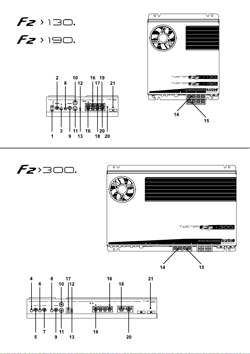
crossover
lp
455570
hp
hertz volt
SERIES
SERIES
statusinput supplyoutput
preamplifiercrossover
L
110
300
(mono)
4.3
0.7
0.4
0.26
0.17
l/r
off
on
mono
R
prt
supply
speakers
L
rem
bridge
on
cap
R
gnd
12
fuse
SERIES
supplyoutputinput statusrem
high pass low pass .
20222635150
off
off
hertz
on
on
455570
110
300
l/r
hertz volt
mono
preamplifierCrossover
L
(mono)
4.3
0.7
0.4
0.26
0.17
rem
on
R
prt
speakers
bridge
L R
supply
gnd 12
fuses
30 A
30 A
Page 75

input supplyoutputstatusrem
high pass low pass .
20222635150
off
off
hertz
hertz
on
on
preamplifierCrossover
L
455570
110
300
(mono)
4.3
0.7
0.4
0.26
0.17
l/r
rem
volt
mono
on
R
prt
speakers
L R
bridge
supply
gnd 12
fuses
30 A 30 A 30 A
Page 76

I
G .T .trading si riserva il diritto di apportare modifiche o miglioramenti ai prodotti illustrati senza alcun
preavviso - La disponibilità dei prodotti illustrati può essere sottoposta a variazioni - I prodotti
presenti su questo Manuale d’uso rappresentano solo una parte dei prodotti Audio System - T utti i
marchi eventualmente citati sono stati utilizzati esclusivamente a scopo descrittivo ed ogni diritto
appartiene ai relativi proprietari - La riproduzione totale o parziale di questo Manuale d’uso è vietata
GB
G.T.trading reserves the right to make modifications or improvements to the products illustrated
without notice thereof - The availability of the products illustrated is subject to change - The
products described in this User's Guide represent just a part of the Audio System product s available
- All brands and trademarks mentioned have been used exclusively for description purposes and all
rights belong to the respective owners - Total or partial reproduction of this User's Guide is
prohibited.
F
G.T.trading se réserve le droit d'effectuer des modifications ou des améliorations sur les produits
illustrés, sans aucun préavis - La disponibilité des produits illustrés peut subir des variations - Les
produits présentés dans ce Manuel d'utilisation ne constituent qu'une partie des produits Audio
System - T outes les marques éventuellement citées ont été utilisées exclusivement à titre descriptif
et tous les droits appartiennent à leur propriétaire respectif - La reproduction totale ou partielle de
ce Manuel d'utilisation est interdite.
D
G .T. trading behält sich das Recht vor, die beschriebenen Produkte ohne jegliche Vorankündigung zu
verändern oder zu verbessern. Die Verfügbarkeit der dargestellten Produkte kann Änderungen
unterliegen. Die in diesem Benutzerhandbuch beschriebenen Produkte stellen nur einen T eil unseres
Audio-System-Angebots dar. Alle hier gegebenenfalls erwähnten Marken wurden ausschließlich zum
Zweck der Beschreibung angegeben. Alle Rechte sind den jeweiligen Markeninhabern vorbehalten
Die auch ausschnittsweise Vervielfältigung des vorliegenden Benutzerhandbuchs ist untersagt.
G.T.trading se reserva el derecho a realizar modificaciones o mejoras en los productos indicados
E
sin previo aviso. La disponibilidad de los productos indicados puede estar sujeta a variaciones. Los
productos presentes en este manual de uso representan sólo una parte de los productos Audio
System; todas las marcas citadas se han utilizado exclusivamente con fines descriptivos, y todos
los derechos pertenecen a los correspondientes propietarios. La reproducción total o parcial de
este manual de uso está prohibida.
 Loading...