

Page 1
D0 4- ME N0 97 -0 0
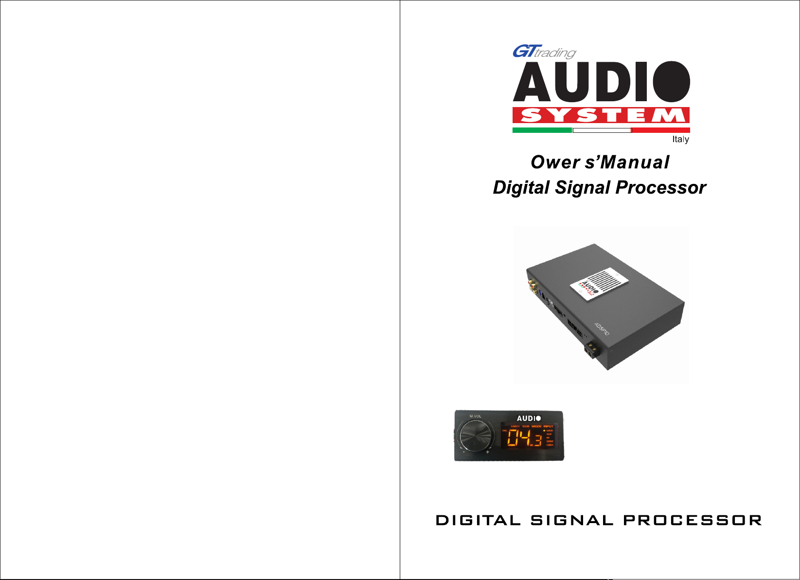
ADSP10
Page 2
5
6
IN TE RFACE IN TR ODUCT IO N
7.
8
9
05
06
7-11
12
12
Page 3
2
REM SPE AKE R OU T
FUSE
REM SPE AKER OU T
FUSE
FUSE
RE M+
Page 4
5
5
6
6
6
2
5 6
Page 5
PRODUCT BRIEF INTRODUCTION
PRODUCT BRIEF INTRODUCTION
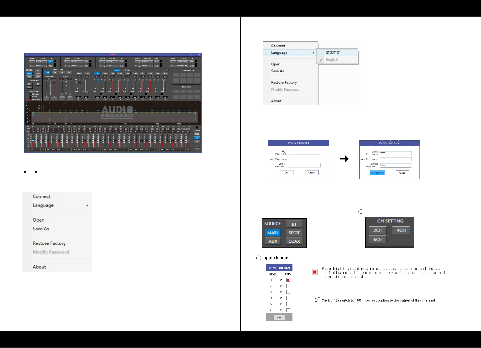
6.2 Interface introduction
1.DSP interface guidance
2. FILE MAIN MENU
1. Connect(connect to the DSP)
1
2. Language(choose you need language)
3. Open(To load preset file in PC folder)
4. Save(To save setting to PC)
5. Save as(To save another file setting to PC)
6. Restore Factory(To save preset file in DSP)
7.Modify Password
9. Read From Device
10. About
11. Exit
3. INPUT MODE.
To select different input devices.
4. CHANNAL SETING.
CH mode(2CH 4CH 6CH MIX).
1
[ 7 ]
2
1. 2. 3. 4. 5. 6
1
2
[ 8 ]
Page 6
PRODUCT BRIEF INTRODUCTION
PRODUCT BRIEF INTRODUCTION
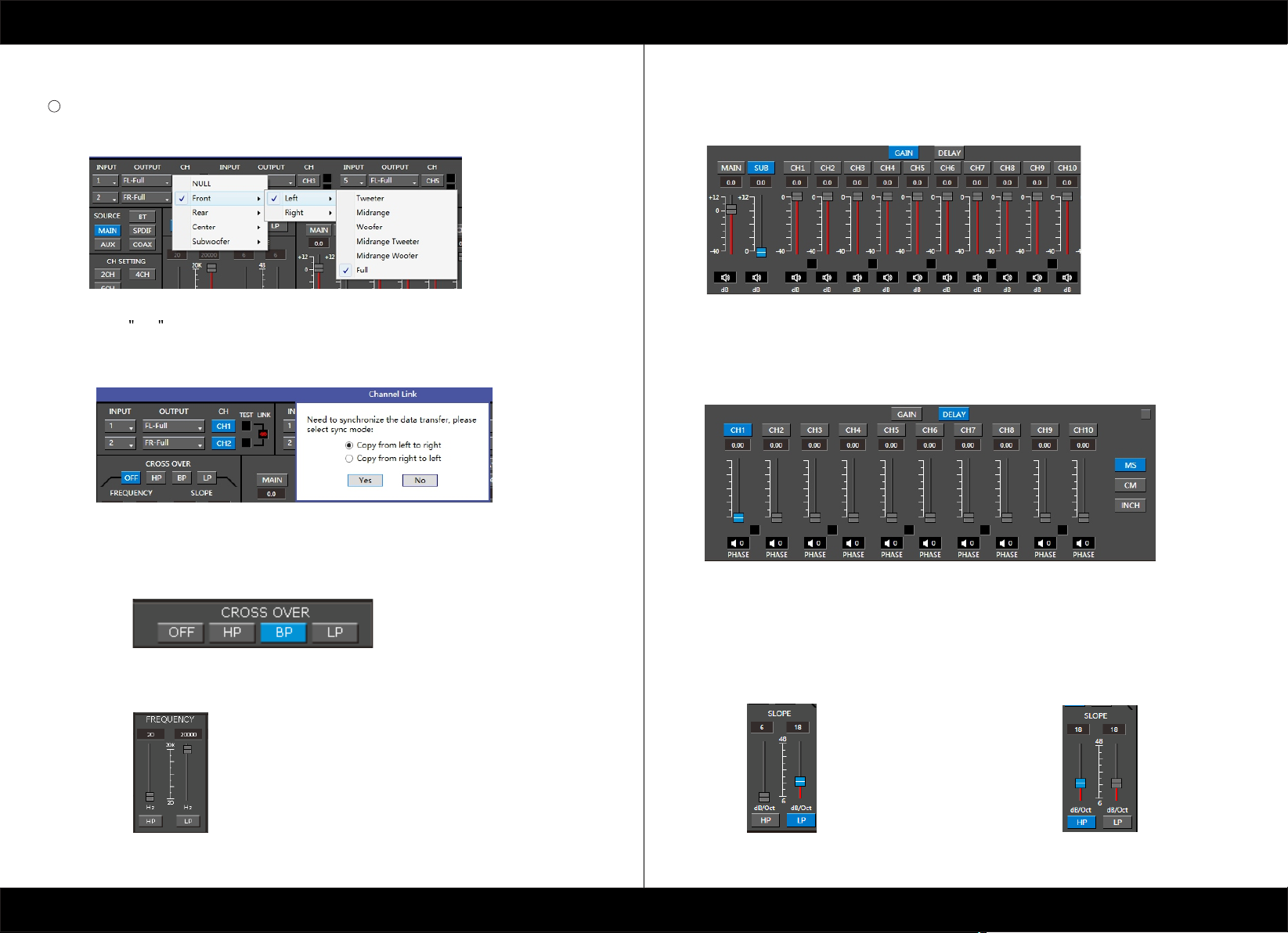
Output channel:FL FullRange.FR FullRange.
3
When you click the drop-down button, you can choose the state of the channel input.
There is : Null.Front.Rear.Center.Subwoofer and Full.Tweeter.Mid-T.Midrange.M-WF. Woofer.
Options on the Link are for combine setting for Left CH and Right CH .
Options on the Left CH/right CH allow you tone each selected channel respectively.
5. CROSSOVER X-TPE.
To choose different crossover type, for example select CH selection on 3RD
spot .that would locate CH you want to choose for crossover configuration .
7. GAIN.
0--40dB is optional range for gain control kf every CH.
8. DELAY.
1.Auto configuration(base on 1.5 setting).
2.Manual configuration, change specifications in selected CH manually.
6. CROSSOVER FREQUENCY.
Set frequency of LP/HP individually .
[ 9 ]
9. LP/SLOPE.
1.6dB/oct 12dB/oct 18dB/oct 24dB/oct 30dB/oct
36dB/oct. 42dB/oct 48dB/oct are available.
M1=FL+FR. M2=FL+FL.
M3=FR+FR.
10. HP/SLOPE.
1.6dB/oct 12dB/oct 18dB/oct 24dB/oct 30dB/oct
36dB/oct.42dB/oct 48dB/oct are available.
M4=FL+RL+SUBL. M4=FR+RR+SUBR.
[ 10 ]
Page 7
PRODUCT BRIEF INTRODUCTION
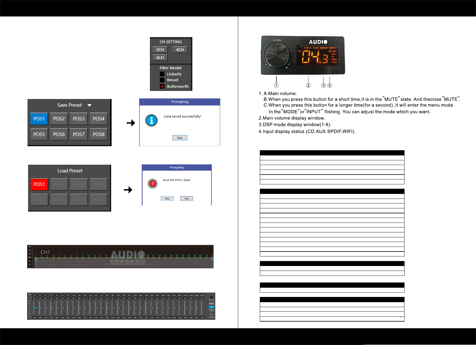
11. Filter Model.
To choose different Filter type Linkwitz Bessel Butterworth.
12. WRITE.
To Write To Device(POS1-POS8).
13. READ.
To Read From Device(POS1-POS8).
PRODUCT BRIEF INTRODUCTION
8.REMOTE INTRODUCTION
9.TECHNICAL FEATURES
POWER SUPPLY
Voltang e
Idlin g current
Switc hed off wit hout DRC
Switc hed off wit h DRC 4mA
Remot e IN voltage
Remot e OUT volta ge
12 VDC( 130mA)
8.5-1 5VDC
0,5A
5mm
6-15 VD C
14. X-OVER AND EQ CHARTS.
1.Red lines and slopes will change accordingly when
HP/LP of crossover and EQ are modified.
2.EQ all frequency points can be move left or right.For 20Hz-20KHz can be any Regulation.
15. EQ SETTING.
Q volue=1-12.
[ 11 ]
SIGNAL STAGE
Disto rtion - THD @ 1 kHz, 1V RMS O utput
Bandw ith @-3 dB
S/N rat io @ A weigh ted
Maste r Input 98 dBA
Auxin put
Chann el Separation @ 1 kHz
Input S ensitivity(Sp eaker In)
Input S ensitivity(Au x In)
Input S ensitivity(Ph one)
Input S ensitivity(Sp eaker In)
Input S ensitivity(Au x)
Input S ensitivity(Ph one)
Max OUT PUT Level (RMS) @ 0.1 % THD
INPUT STAGE
High Le vel(Speaker)
Low lev el(Pre)
CONNECTION
From/ To Perso nal Computer
CROSSOVER N.5 (one each output ch annel)
Filte r Type
Slope S etting
Cross over frequency
Phase c ontrol indepent s etting fo r each chan nel 0 - 180
[ 17 ]
0,2-5 V R MS
1. 2.3 .4.5 .6. i n
1. 2.3 .4.A UX in
1 x USB/B (1.1/2.0) 5M
Full/ High/Low Pass /Ba nd Pass
6/12/ 18/24/30/42/4 8 dB
68 step s @ 20- 20kHz
0,000 4%
20-22 kHz
96dBA
95 dB
2-15 V RM S
10kЩ
22kЩ
4 V RMS
[ 12 ]
 Loading...