

Page 1

Thank you for using our Audio Space The Buffer-one Vacuum Tube Stereo Bufferamplifier. Please read this operation manual carefully before using it.
I SPECIFICATIONS
■ Line Output 2V (8V P-P max).
■ Output impedance <500Ω
■ Frequency response 10Hz~120kHz + 1dB
■ THD < 0.3 % 20Hz-20KHz (Ref. Output)
■ Input sensitivity 150mV (Line Input)
■ Input impedance 30kΩ(RCA) (Line Input)
■ S/N ratio >89dB (Hum Noise<150uV)/Line Output
■ Channel Balance: <1dB 20Hz-20KHz
■ Channel Separation: >76dB (1KHz-3.3Khz)
■ Tubes: 6922x2 (6DJ8, ECC-88)
■ Power requirements 110/220VAC±5%, 50/60Hz
■ Weight N.W.: 5.5Kg G.W.: 6.68Kg
■ Dimension 365×170×153.5mm (D×W×H)
*NOTE: Voltage selector is on the bottom side of the Cabinet.
II OPENING THE PACKAGE
Please check the carton carefully whether there are any damages before you open it.
Put it on a flat surface with the arrow upward. Rip away the sealed tape and open the
carton, then you’ll find:
1 set Buffer-amplifier of Audio Space Buffer-one,
①
an operation manual,
②
a warranty card,
③
a power supply cord,
④
two fuses.
⑤
Note: Please fill out your warranty card in time, and hand it in to your dealer or send
it to the sales department of our company to ensure the after-sales service.
Take out the Buffer-amplifier carefully, watch the front panel and read the diagram 1.
Then watch the rear panel and read the diagram 2.
Note: Be sure to use at rated voltage. Please check whether the rated voltage marking
on the back plate corresponds to your line voltage. If not, please contact your dealer.
Suggestion: Please keep the carton and the other wrappings well, perhaps you’ll use
them when move the Buffer-amplifier.
1
Page 2

III CONNECTION
Select the suitable output impedance for your speaker and connect the amplifier to
the speaker with sound specialized line, don’t confuse L with R.
Connect the Buffer-amplifier input to the sound source (CD Player, Pre-amp. or
sound source) with the signal wire on the rear panel. Connect the Buffer-amplifier
output to main amplifier (Pre-amp., Integrated-amp. or Power-amp.) with the signal
wire on the rear panel. Set the “ Input selector “ to the correct position. Don’t confuse
L with R.
Then connect the power cord. At first insert the cord plug into the power socket,
and next, insert the other end of the cord into an electrical outlet.
NOTE: *1. Red is Right Channel (R), Black is Left Channel (L).
*2. Read the connection diagram 3, 4, 5, 6 or 7 and select one of the
connection format to fit your audio equipment.
IV TURNING ON
When you are sure the connections are correct, adjust the “ Volume” of
Pre-Amplifier to the lowest position and turn on the Buffer-Amplifier by turning the
“Power” switch then the “Red LED (Stand By Indicator)” will light up and the delay
circuit will be start automatically. After about 45-50 seconds the “Blue LED (Operate
Indicator)” will light up, indicating the Buffer-amplifier is normal. Then you will
enjoy the music by adjusting by the “Volume” of “Pre-Amplifier” while your sound
source is working.
Caution: *To prevent damage to the Amplifier, never cut off the speaker cable while
the unit is on and never short-circuit Positive (+) and Negative (-) speaker terminals
* Be sure to set the “Volume” of Pre-Amplifier control to the Lowest
position before turning on or disconnecting the speakers while the unit is on.
Note: Never exchange the position of the vacuum tubes.
V WARNING
● Be careful when carrying in order to avoid damaging.
● To reduce the risk of electric shock, don’t remove the cover.
● Don’t attempt to repair the product by yourself.
● No user serviceable parts inside. Refer servicing to qualified service personal.
● Keep liquid away from the amplifier. If you spill liquid into the unit, pull out the
power plug at once and consult your dealer.
2
Page 3
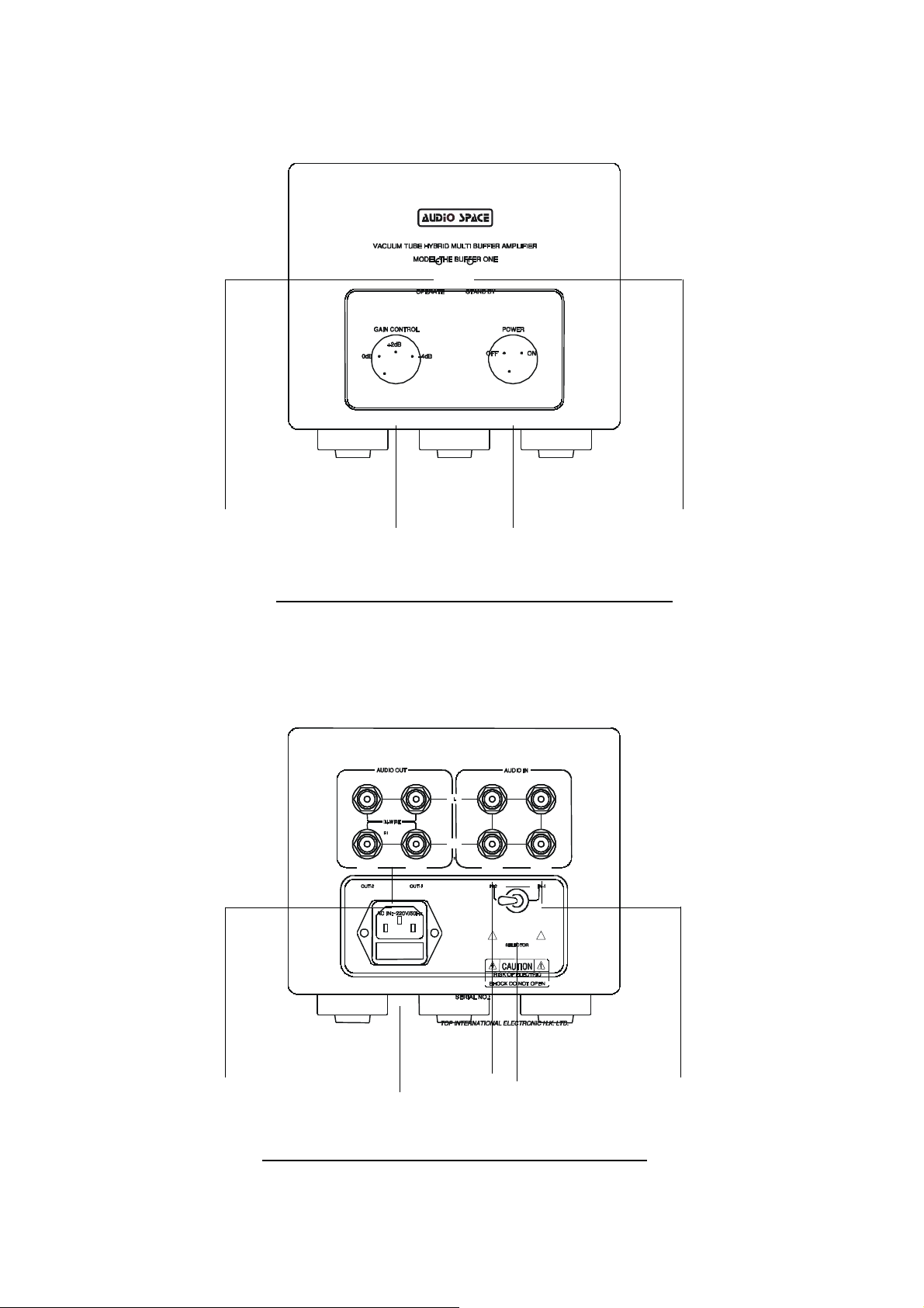
【DIAGRAM】
CONTROL
① ④② ③
DIAGRAM 1. BUFFER-ONE FRONT PANEL
OPERATE INDICATOR ②GAIN
①
① ⑤③② ④
DIAGRAM 2. BUFFER-ONE REAR PANEL
AUDIO OUTPUT ②POWER SOCKET
①
(W/FUSE)
INPUT2 ④INPUT SELECTOR
③
3
Page 4
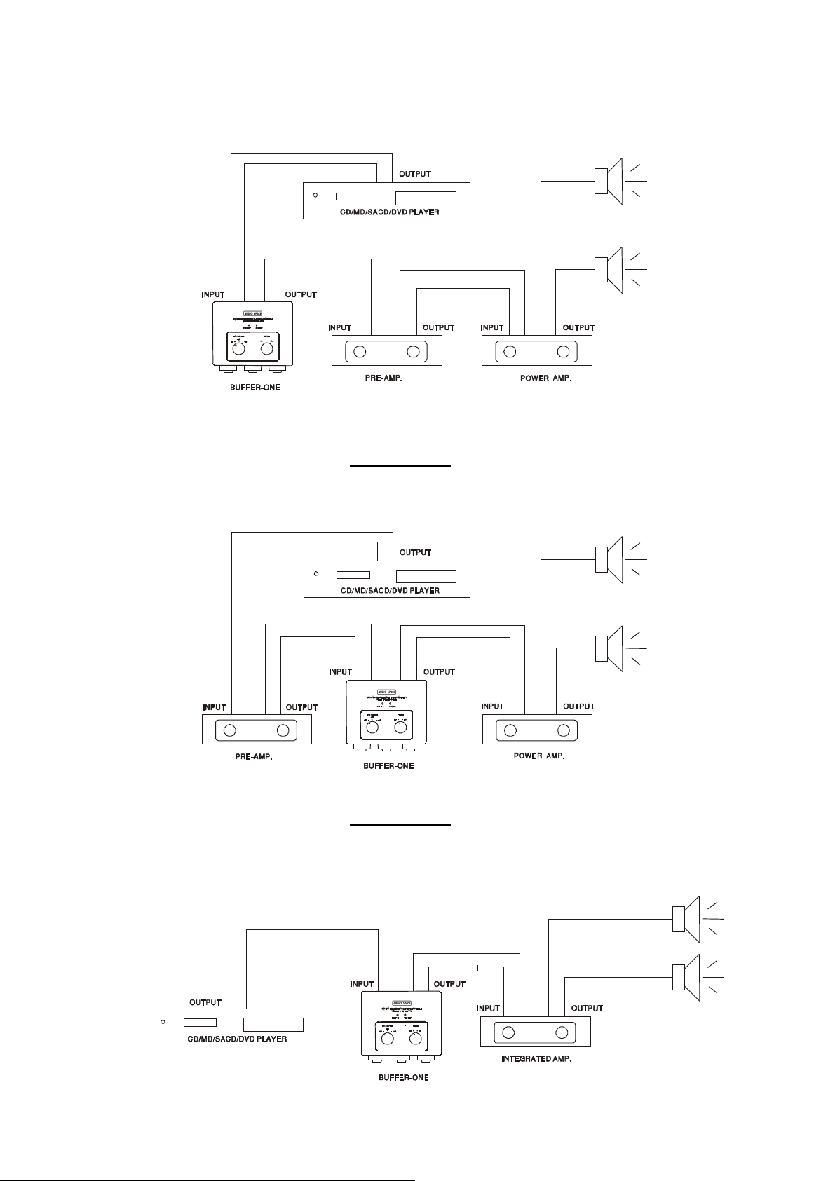
【CONNECTION DIAGRAM】
DIAGRAM 3.
DIAGRAM 4.
4
Page 5
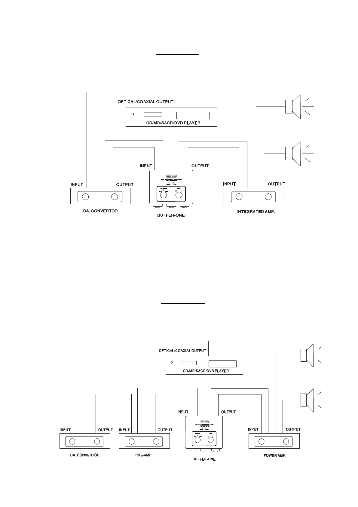
DIAGRAM 5.
DIAGRAM 6.
5
Page 6

VI WARRANTY SERVICE
The fuse is broken.
▲ This product is warranted for a period of twelve months beginning from the date
of purchase.
▲ To obtain warranty service, the warranty card bearing your dealer’s chop or
signature must be return to your dealer or our company with the days from the
date of purchase.
▲ The defective product must be returned to your dealer or our company for
repairing when your dealer or our company accepts your requirement.
▲ The warranty doesn’t extend to any product that has been opened by you without
permission of our company.
VII TROUBLESHOOTING
Basic troubleshooting of an amplifier is similar to troubleshooting of any other
electrical or electronic equipment. Always check the most obvious possible causes
first. To give you a few ideas of what to look for, check the following.
Problem Cause Remedy
No power when POWER
is pressed.
The location of music is
not fine.
No sound Volume control is set to
Mains plug not
⑴
inserted correctly.
⑵
L and R of input or output
are mistaken or positive
and negative of speaker
terminal is mistaken.
minimum
Source Selector set to
wrong
Speakers are not connected
Plug in securely.
⑴
Replace the fuse with a
⑵
new one of the same
type .
Reconnect it.
Turn up the volume
Check Selector
Check speaker cables
The noise is overloud. Not fine signal shielded
Wrong input is selected
cable.
6
Check input selection
Replace the signal cable
with a good one
Put the connections in
Page 7

The signal cable, power
good order. Keep the
supply cord and the video
frequency cable are placed
signal cable away from the
others.
too close or get tangled up.
Components or circuits are
Contact your dealer
in trouble.
VIII NOTICE
The information in this manual is subject to change without notice.
7
 Loading...