

Page 1
REFERENCE 160S
User’s Manual
Page 2
Customers Come First
Quality Every Day
Advancing Our Legacy
Commitment to Excellence
Page 3
Thank you for choosing the
Reference 160S to be a part of your
high performance music listening
system. After nearly 50 years, our
focus remains the advancement
of the state-of-the-art in music
reproduction. Every component
is meticulously hand-crafted and
personally auditioned before it
leaves our factory. Our attention to
detail, customer service, and product
support create unprecedented value.
An Audio Research component
is more than a purchase, it’s
an investment.
We understand you are eager to
begin listening; however, please
take a few minutes to read through
this guide for useful information
concerning the operation of your
please allow an appropriate
break-in period to fully appreciate
provide to your system.
After reading the user guide, if you
have further questions regarding
Audio Research customer service—
Thank You.
they will be happy to help you make
the most of your new component.
Happy Listening!
Page 4
Safety Instructions
Important Safety Instructions
triangle, is intended to alert the user to the presence of uninsulated
“Dangerous voltage” within the product’s enclosure that may be of
The exclamation point within an equi-lateral triangle is intended
to alert the user to the presence of important operating and maintenance
(Servicing) instructions in the literature accompanying the product.
1. Read these instructions.
2. Keep these instructions.
3. Heed all warnings.
4. Follow all instructions.
5. Do not use this apparatus near water
6. Clean only with dry cloth.
7. Do not block any ventilation openings. Install in accordance
with the manufacturer’s instructions.
8. Do not install near any heat sources such as radiators, heat registers,
9. Do not defeat the safety purpose of the polarized or grounding-type plug. A
polarized plug has two blades with one wider than other. A grounding type
plug has two blades and a third grounding prong. The wide blade or the third
outlet, consult an electrician for replacement of the obsolete outlet.
10. Warning: The apparatus shall be connected to a MAINS socket outlet with
a protective earthing connection.
11. Protect the power cord from being walked on or pinched particularly at plugs,
convenience receptacles and the point where they exit from the apparatus.
12.
2
Page 5

13. Unplug this apparatus during lightning storms or when unused for long periods of time.
14.
has been damaged in any way, such as power-supply cord or plug is damaged, liquid
has been spilled or objects have fallen into the apparatus, the apparatus has been
exposed to rain or moisture, does not operate normally, or has been dropped.
15. WARNING: TO REDUCE THE RISK OF FIRE OR ELECTRIC SHOCK, DO
NOT EXPOSE THIS APPARATUS TO RAIN OR MOISTURE
16. DO NOT EXPOSE THIS APPARATUS TO DRIPPING OR SPLASHING AND THAT NO
OBJECTS FILLED WITH LIQUIDS, SUCH AS VASES, SHOULD NOT BE PLACED ON
THE APPARATUS
17. TO COMPLETELY DISCONNECT THIS APPARATUS FROM THE AC MAINS,
DISCONNECT THE POWER SUPPLY CORD PLUG FROM THE AC RECEPTACLE.
18. THE MAINS PLUG OF THE POWER SUPPLY CORD SHALL REMAIN READILY ACCESSIBLE.
3
Page 6
Contents
Safety Instructions ...................................... 2
Warnings.......................................................5
A note about packaging................................5
Handling and moving Reference 160S..........5
Installation ...................................................6
Top view .........................................................6
Before operating the Reference 160S ...........6
Tube cage removal and installation .............7
Ventilation requirements ............................10
In your system ..............................................10
A note about vacuum tube life expectancy ..10
Connections ................................................ 11
Back Panel Connections............................... 11
Input Connectors ......................................... 11
Maintenance .............................................. 18
Vacuum Tubes ............................................. 18
Servicing ...................................................... 18
Caution ........................................................ 18
Cleaning ....................................................... 18
Disposal and Recycling Guidelines ............. 18
Warranty..................................................... 19
.............................................. 20
Output Connectors ...................................... 11
Matching.......................................................12
Loudspeaker Cable Distance .......................12
Remote Turn-on .......................................... 13
RS-232 Control ............................................ 13
A.C. Power Connection ............................... 13
Operation ....................................................14
Front Panel Controls and Displays ..............14
Start-Up ........................................................15
Shut-Down ...................................................15
Front Panel Button Functions .....................16
Back Panel Toggle Switch Functions ...........16
...............................................16
Auto Bias ......................................................17
Hour Counter ...............................................17
Break-in .........................................................17
4
Page 7

Warnings
To prevent fire, or shock hazard, do not expose your Reference 160S to rain or moisture.
Do not place objects containing water on top of this unit.
This unit contains voltages which can cause serious injury or death. Do not operate with covers
removed. Refer servicing to your authorized Audio Research dealer or other qualified personnel.
The detachable power cord on your Reference 160S is equipped with a heavy gauge, 3-conductor
cable and a standard three-prong grounding plug in North America. For absolute protection, do
not defeat the ground power plug. This provides power line grounding of the Reference 160S
chassis to provide absolute protection from electrical shock.
The appliance coupler (a.c. power connector) at the rear of this unit must be accessible for
emergency power disconnect.
For continued protection against fire hazard, replace the fuse only with the same type and
rating as specified at the fuse holder.
The power button on the front of this unit, when off, does not disconnect all power from this
unit. This unit is in sleep mode when not on.
This unit is RoHS compliant.
A note about packaging...
Save all packaging in a dry place away from fire hazard. Your Reference 160S amplifier is a
precision electronic instrument and should be properly cartoned any time shipment is made.
You may not have occasion to return your unit to the factory for service, but if that should prove
necessary, or other occasion requiring shipment occurs, the original packaging will protect your
Reference 160S from unnecessary damage or delay.
Important!
The AC Power Supply Cord must be disconnected from the amplifier before replacement or
installation of vacuum tubes.
Handling and moving the Reference 160S
The Reference 160S weighs 100 lbs. (45 kg). Two people are required to safely lift the amplifier.
The chassis has both front and rear pairs of handles for this purpose. Note the rear of the
amplifier with the power and output transformers is the heavy end.
5
Page 8
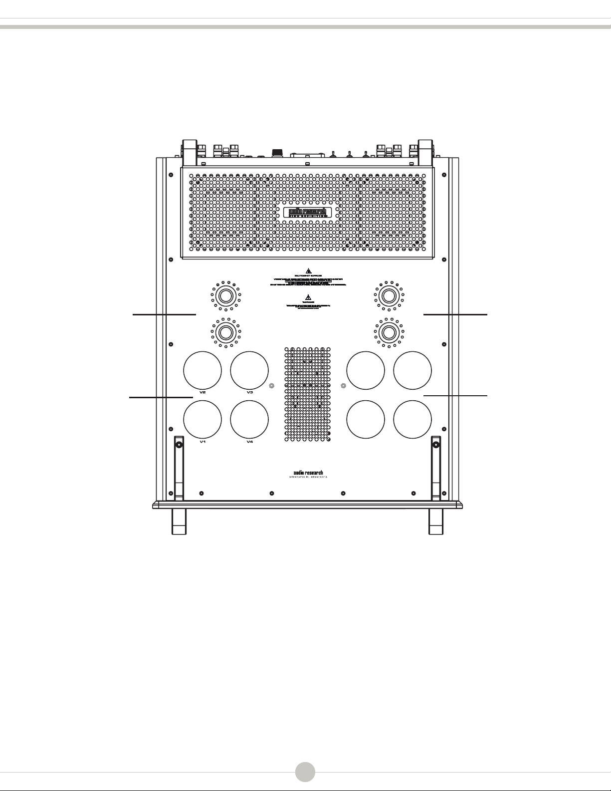
Installation
Top View
6H30
Vacuum Tubes
KT150
Vacuum Tubes
V10
V9
V12
6H30
Vacuum Tubes
V11
V6
V7
KT150
Vacuum Tubes
V8V5
Before operating the Reference 160S
Your Reference 160S amplifier is shipped with the vacuum tubes packed in foam blocks. These
must be unpacked and installed before you attempt to operate the amplifier. Included are eight
matched KT150s and 4 matched 6H30s. Follow the procedure below to remove the top cage
prior to vacuum tube installation.
6
Page 9
Tube cage removal and installation
CAUTION: THIS STEP FOLLOWED BY USER IS ALLOWED ONLY ONCE FOR THE INITIAL
INSTALLATION BEFORE POWERING UP THE PRODUCT FIRST.
Important!
The AC Power Supply Cord must be disconnected from the amplifier before replacement or
installation of vacuum tubes.
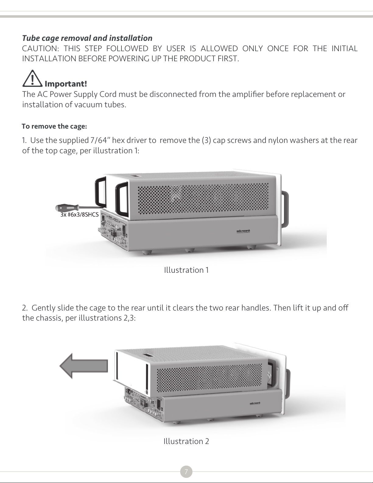
To remove the cage:
1. Use the supplied 7/64” hex driver to remove the (3) cap screws and nylon washers at the rear
of the top cage, per illustration 1:
Illustration 1
2. Gently slide the cage to the rear until it clears the two rear handles. Then lift it up and off
the chassis, per illustrations 2,3:
Illustration 2
7
Page 10
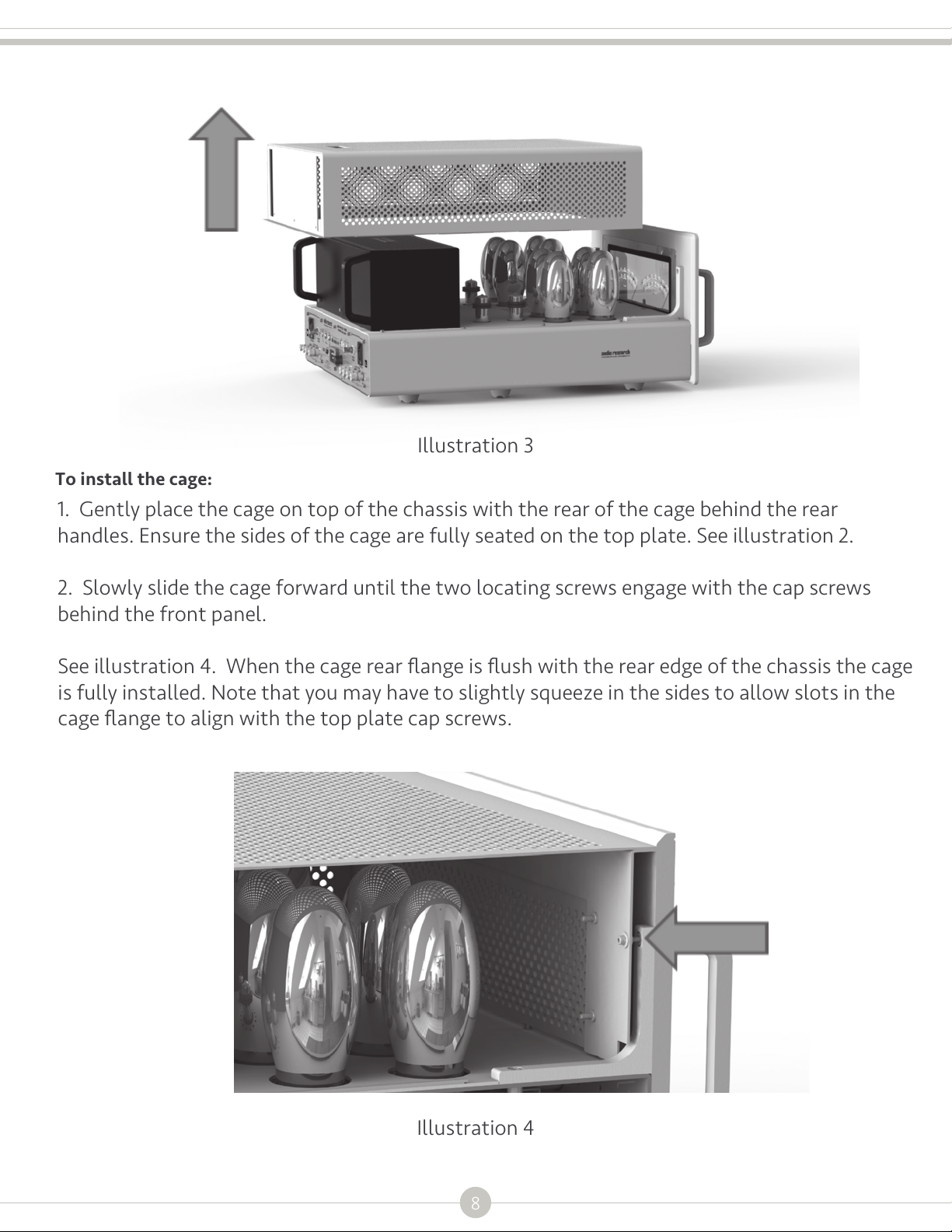
Illustration 3
To install the cage:
1. Gently place the cage on top of the chassis with the rear of the cage behind the rear
handles. Ensure the sides of the cage are fully seated on the top plate. See illustration 2.
2. Slowly slide the cage forward until the two locating screws engage with the cap screws
behind the front panel.
See illustration 4. When the cage rear flange is flush with the rear edge of the chassis the cage
is fully installed. Note that you may have to slightly squeeze in the sides to allow slots in the
cage flange to align with the top plate cap screws.
Illustration 4
8
Page 11

Vacuum tube installation
Carefully remove each vacuum tube from its protective foam and match its location ‘V’ number
(written on the base of the tube) to the ‘V’ number screened next to each socket on the top
plate of the Reference 160S. Firmly seat tube in its matching socket, taking care to align the key
at the base of each KT150 to its socket hole.
The 6H30 tubes V9-V12 are not keyed and care must be taken to align the pins to the sockets. A
small flashlight will assist in this process.
Retain the foam tube shipping blocks with the other packing materials for possible future use.
Warning: Tube replacement shall be done by skilled or service personnel, or qualified
technician.
9
Page 12

Ventilation Requirements
Installation
The Reference 160S employs forced air cooling using two ultra-quiet internal fans, located on
each side of the bottom cover about one third of the way back from the front of the chassis.
These fans draw cool air from under the unit, circulate the air internally to cool components,
and exhaust the heated air from grilles on the chassis top plate and transformer cover. It is very
important that cooling airflow to these fans not be impeded in any way by placing the unit on
carpet or a soft surface that might allow the Reference 160S to settle into the surface and
impede the airflow.
A minimum of 8 inches (21cm) clearance is required above the top of the amplifier. If the unit is
operated in an enclosure or equipment rack, keep in mind the above ventilation requirements
to make certain that adequate airflow above, to each side and to the rear is provided.
The ambient operating temperature should never exceed 86⁰F (30⁰C). Improper installation
will cause premature component and /or tube failure and will affect your warranty as well
as the service life of the unit. If you have any questions about correct installation,
pleaseconsult with your authorized Audio Research dealer or contact the factory at
[email protected].
The forced air cooling of the Reference 160S will over time cause a buildup of internal dust
inside the unit that may impede proper cooling and result in reduced component life. Periodic
cleaning of the unit is strongly recommended. Refer to Cleaning, under the Maintenance
section of this manual for instructions. It is normal for a vacuum tube amplifier to run quite
warm, and if used for prolonged periods, hot to the touch. All components within are, however,
operated at safe, conservative levels and will not be improperly affected thereby, providing the
requirements outlined above are adhered to.
In Your System
To ensure normal component life and safe operation, this unit should only be operated in an
upright position. The special non-marring elastomer feet provide adequate spacing and
stability only on a smooth, hard surface, and must be on a dedicated shelf or amp stand capable
of supporting 100 lbs. Check with the manufacturer of your support system to be sure it is rated
to handle this weight.
The Reference 160S power transformer generates a magnetic field that could, in some
installations, induce hum in sensitive electronics such as turntables, phono cartridges and
phono stage preamplifiers. For this reason, we recommend that any such products and their
interconnecting cables be kept a minimum of 12” away from the Reference 160S.
Vacuum Tube Life Expectancy
The vacuum tubes in your Reference 160S have been burned in, tested and electrically matched
to provide the best performance and reliability of your amplifier. That said, vacuum tubes wear
out with use and must be periodically replaced. The KT150 output tubes in the Reference 160S
should have an estimated life of approximately 3000 hours, while the smaller 6H30 tubes
should have a life expectancy of approximately 4000 hours. These life expectancies are only
approximate. Please consult with your dealer or Audio Research customer support for more
information. Warning: Tube replacement shall be done by skilled or service personnel, or
qualified technician.
improperly affected thereby, providing the
requirements outlined above are adhered to.
In Your System
To ensure normal component life and safe
operation, this unit should only be operated
in an upright position. The special
non-marring elastomer feet provide
adequate spacing and stability only on a
smooth, hard surface, preferably on a
dedicated shelf or amp stand capable of
supporting 100 lbs. Check with the
manufacturer of your support system to be
sure it is rated to handle this weight.
The Reference 160S power transformer
generates a magnetic field that could, in
some installations, induce hum in sensitive
electronics such as turntables, phono
cartridges and phono stage preamplifiers.
For this reason, we recommend that any
such products and their interconnecting
cables be kept a minimum of 12” away from
the Reference 160S.
Vacuum Tube Life Expectancy
The vacuum tubes in your Reference 160S
have been burned in, tested and electrically
matched to provide the best performance
and reliability of your amplifier. That said,
vacuum tubes wear out with use and must
be periodically replaced. The KT150 output
tubes in the Reference 160S should have an
estimated life of approximately 3000 hours,
while the smaller 6H30 tubes should have a
life expectancy of approximately 4000
hours. These life expectancies are only
approximate. Please consult with your
dealer or Audio Research customer support
for more information. Warning: Tube
replacement shall be done by skilled or
service personnel, or qualified technician.
10
Page 13
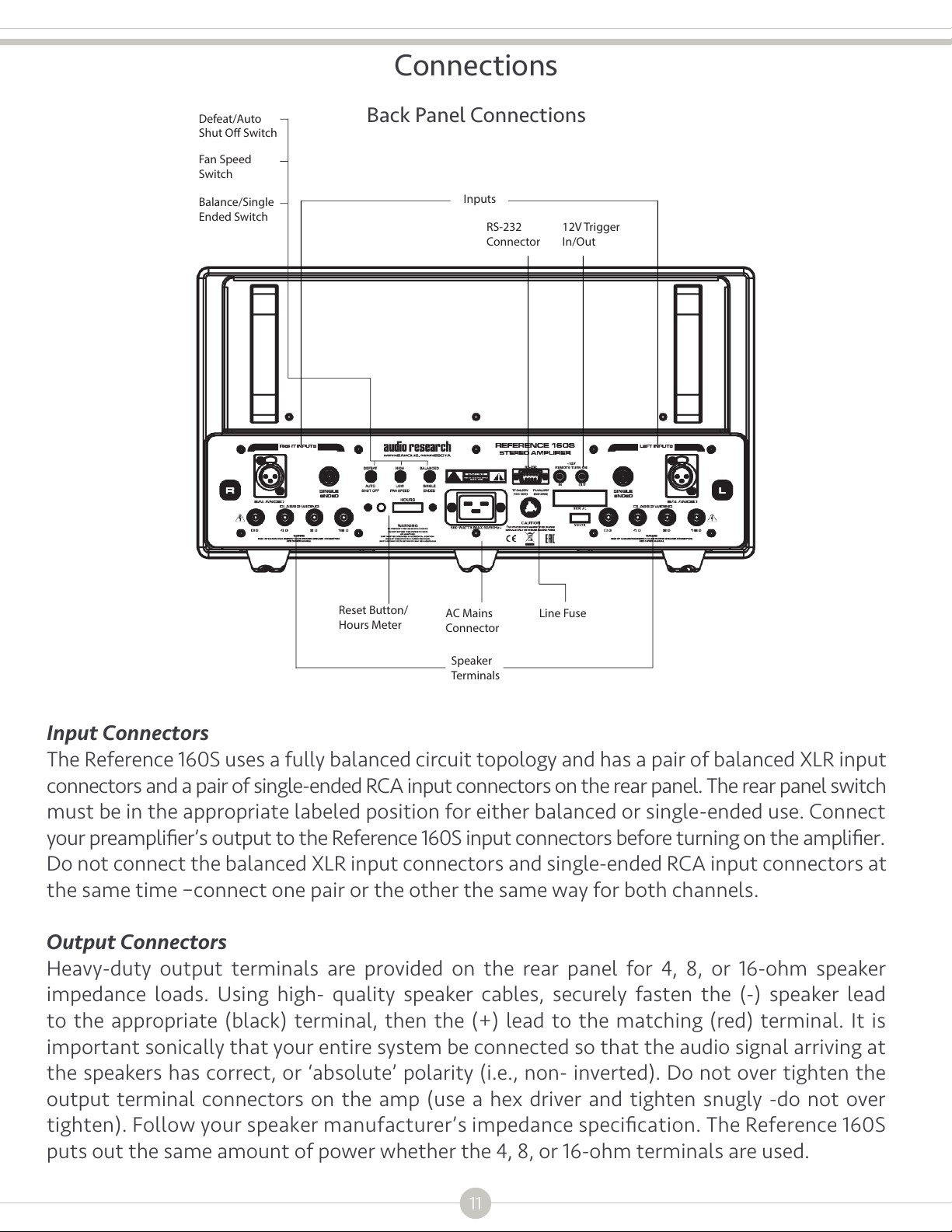
Connections
Defeat/Auto
Shut O Switch
Fan Speed
Switch
Balance/Single
Ended Switch
Back Panel Connections
Inputs
RS-232
Connector
12V Trigger
In/Out
Reset Button/
Hours Meter
AC Mains
Connector
Speaker
Terminals
Line Fuse
Input Connectors
The Reference 160S uses a fully balanced circuit topology and has a pair of balanced XLR input
connectors and a pair of single-ended RCA input connectors on the rear panel. The rear panel switch
must be in the appropriate labeled position for either balanced or single-ended use. Connect
your preamplifier’s output to the Reference 160S input connectors before turning on the amplifier.
Do not connect the balanced XLR input connectors and single-ended RCA input connectors at
the same time –connect one pair or the other the same way for both channels.
Output Connectors
Heavy-duty output terminals are provided on the rear panel for 4, 8, or 16-ohm speaker
impedance loads. Using high- quality speaker cables, securely fasten the (-) speaker lead
to the appropriate (black) terminal, then the (+) lead to the matching (red) terminal. It is
important sonically that your entire system be connected so that the audio signal arriving at
the speakers has correct, or ‘absolute’ polarity (i.e., non- inverted). Do not over tighten the
output terminal connectors on the amp (use a hex driver and tighten snugly -do not over
tighten). Follow your speaker manufacturer’s impedance specification. The Reference 160S
puts out the same amount of power whether the 4, 8, or 16-ohm terminals are used.
11
Page 14

Connections
Matching
It is important to use as close as possible an impedance match between the amplifier and
speaker for optimum transfer of power to the speaker with minimum distortion. In the case of
speaker systems with significant variations in impedance throughout the frequency spectrum,
such as most electrostatic types, determine the best impedance match empirically for best
overall sonic results by trying different output taps. Connect the Reference 160S input to the
preamplifier or electronic crossover using only the highest grade of audio interconnect cables.
To avoid sonic degradation use the shortest practical length of cables.
Important
Use the best available speaker wires and interconnects. Audio Research cannot
emphasize this enough. As better components and systems are developed, it becomes
increasingly important to avoid the limitations of inferior system interconnections.
12
Page 15

Connections
Remote Turn-on
The Reference 160S has a built-in 12V DC remote turn-on/off circuit for operation by a master
control system in a home theater or large audio system. Use a 3.5mm (.140”) diameter mini
plug to connect to the +12V IN jack on the rear of the Reference 160S. The tip of the mini plug is
+12V and the sleeve is ground.
The +12V IN jack should be connected to the +12V DC output of the master control system,
using a continuous +12V DC signal at 12mA for the duration of amplifier on-time. Do not use a
momentary or data pulse control signal.
The +12V DC remote jacks have polarity protection, so they will not operate if a-12V DC signal is
accidentally connected, or if the control wires are reversed.
RS-232 Control
The Reference 160S has an RS-232 connector on the back panel, in the event the amplifier is
incorporated into an automated or two-way remote communication system. Please see your
dealer or contact [email protected] to acquire specific codes relative to the RS-232
control.
A.C. Power Connection
It is important that the Reference 160S be connected via its supplied 20 amp IEC 12-gauge power
cord to a secure, dedicated A.C. power receptacle. Never connect to convenience power
receptacles on other equipment. Only use the power switch on the front of the Reference 160S
for On/Off control of the amplifier, or the 12V start-up trigger or RS-232 for remote
installations.
The AC power source for the Reference 160S amplifier should be capable of supplying 15
amperes for 100 or 120 volt units, or 10 amperes for 220 or 240 volt units.
For the very best performance on 100 or 120 volt circuits, the Reference 160S should be
connected to its own AC power circuit branch, protected by a 15 (or 20) amp breaker. The
preamplifier and other audio equipment should be connected to a different power circuit and
breaker, if possible.
The Reference 160S uses a grounding system that does not require a ground- lifter adapter plug
on the A.C. power cord to minimize hum. The power cord supplied with the Reference 160S has
a standard grounding plug to provide maximum safety when properly connected to a grounded
wall receptacle. If there is any question regarding proper grounding procedures in your
installation, seek help from a qualified technician. Caution should be taken before using
custom after-market power cords: they must be at least 12-gauge and have a standard
grounding plug properly installed. These power cords are to be used with caution, at the sole
risk of the owner. If electronic crossovers or other AC powered equipment is used with the
Reference 160S it may be necessary to use ‘ground lifter’ adapters on the power plugs of that
13
Page 16
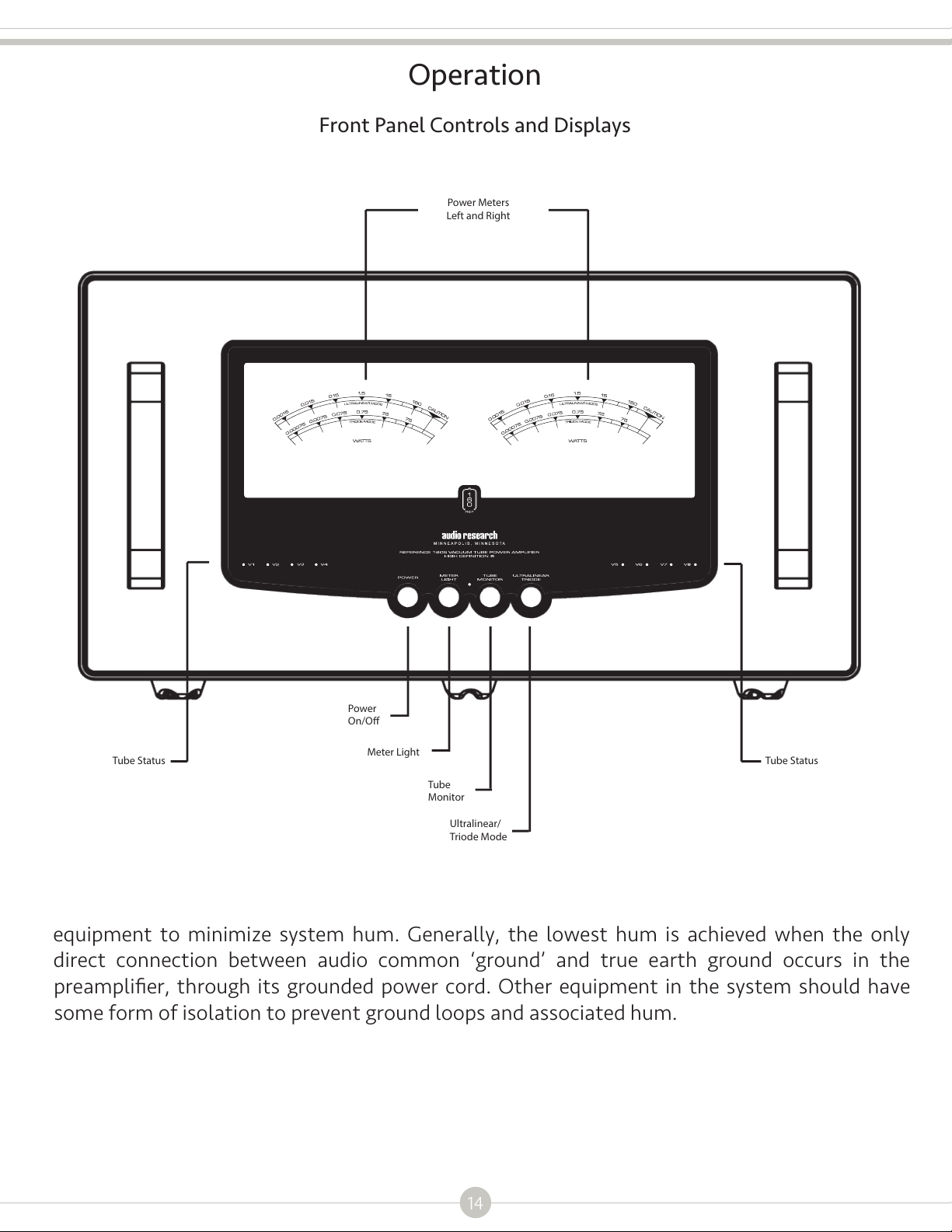
Operation
Front Panel Controls and Displays
Power Meters
Left and Right
Power
On/O
Tube Status Tube Status
Meter Light
Tube
Monitor
Ultralinear/
Triode Mode
equipment to minimize system hum. Generally, the lowest hum is achieved when the only
direct connection between audio common ‘ground’ and true earth ground occurs in the
preamplifier, through its grounded power cord. Other equipment in the system should have
some form of isolation to prevent ground loops and associated hum.
14
Page 17

Operation
Start-Up
• Secure interconnects between the amplifier and your preamplifiero the appropriate output
terminals.
• Attach supplied power cord to rear IEC inlet of amplifier, and plug other end into grounded
A.C. power receptacle.
• Turn on preamp and all other components; mute preamp output.
• Press Reference 160S front panel power switch. Green power LED will flash on/off for
approximately 2 minutes during the auto mute cycle to allow the amplifier to stabilize voltage
before becoming active. The LED will stay on brightly, once the amplifier has stabilized.
• Note: the Reference 160S should be turned on after the other components of your system. If
the Reference 160S is turned on before other components, the amplifier will amplify any
extraneous turn-on noises those components might generate, which could potentially damage
loudspeakers. Good practice dictates that the amplifier should be turned on last and turned off
first in an audio system.
• Unmute preamplifier output, initiate source component signal, and adjust gain as appropriate.
Shut-Down
• Mute preamplifier output.
• Turn off Reference 160S via front panel power switch (or 12V trigger or RS-232).
• To prevent stress to the power supply and vacuum tubes, the control circuitry is programmed
with a “hot restart” lockout to prevent turning the unit on within 2 minutes of shutting the unit
off. If the Reference 160S power switch is pressed during this lockout period, the power LED will
illuminate red to indicate lockout operation. After 2 minutes, normal turn on can be initiated.
15
Page 18

Operation
Front Panel Button Functions
Power
Turns power of Reference 160S on or off.
Meter Light
Adjusts meter light LED display brightness to one of four levels of brightness including “off”.
Tube Monitor
Allows checking the operation of each of the eight KT 150 output tubes (V1-V8). The LED
associated with each output tube will illuminate when operating properly. See Auto Bias
section under Operation for further explanation of its operation.
Ultra-Linear/Triode
Allows selecting ultra-linear (approximately 140 watts/ch.) operation –indicated by green color
of LED above this function button, or triode (approximately 70 watts/ch.) operation –indicated
by blue white color of the power-on LED.
Back Panel Toggle Switch Functions
Auto Shut Off/ Defeat
Allows selecting auto shut-off feature or turning off this feature (see separate Auto Shut Off
paragraph under this Operation section for a more detailed description of this function).
High/Low Fan Speed
Allows adjusting fan speed to either low or high-speed setting.
Balanced/Single Ended
Select balanced switch position for balanced input connection operation or single-ended
switch position for single-ended input connection operation. Do not connect BAL and SE cables
simultaneously. (See Input Connectors paragraph under Connections section for further
information.)
Auto Shut Off
The Reference 160S is equipped with an auto shut-off feature, designed to turn the amplifier off
after two hours of no signal being present at the output of the amplifier.
In the event that quiet music is listened to at very low volumes, there may not be adequate
signal for the auto shut off circuit, resulting in the amplifier turning itself off. If this is the case,
please disengage the auto shut off feature. The auto shut off feature control switch is located
on the back panel of the Reference 160S.
Note: The auto shut off feature is not in the signal path of the amplifier and has no deleterious
sonic effect on music playback.
16
Page 19

Operation
Auto Bias
The Reference 160S incorporates a highly sophisticated auto-bias circuit. There are no
user-adjustable bias controls. There should never be a need to check or adjust the auto-bias
circuit: once it is factory set, no additional adjustment is required. The auto-bias circuit will
“lock in” the idle current of each bank of four KT150 output tubes approximately two minutes
after the Reference 160S is turned on, and continually compensates to maintain the proper bias
as the tubes age. Auto-bias sets the idle current at 65mA per tube.
It is always recommended owners purchase replacement tubes from Audio Research Corp.
Since the auto bias adjusts pairs of tubes, not each individual tube, it is important that 2
matched sets of eight KT 150 output tubes be installed for optimum performance and longest
tube life.
The auto bias circuit will not accommodate output tubes with extremely high or low plate
current readings. Aftermarket tubes may not be tested to the same rigorous standards as
Audio Research tests, so care must be exercised when installing aftermarket tubes. If
uncertain about aftermarket tube requirements, please contact [email protected]
for recommendations.
Audio Research supplies the KT150 output tube in the Reference 160S, providing the highest power and
best sound possible in this amplifier design.
Audio Research has tested the Reference 160S with KT120, KT88 and 6550WE output tubes. The
Reference 160S will produce less power with any of these tubes and the sound will be degraded.
Under no circumstances should any tube not electrically equivelant to the KT150 or 6550WE be
installed. Tubes such as the EL34, KT77, 6L6 should never be installed. Installing tubes such as these
will void the factory warranty and Audio Research will not be liable for any damage.
Contact [email protected] if you have questions regarding tube compatability.
Hour Counter
An LCD hour counter of elapsed tube operating time can be viewed on the back panel. This
displays accumulated hours of vacuum tube service life. If the amplifier is unplugged from A.C.
supply, the total accumulated hours are retained. Next to the hour counter is a recessed hour
counter reset button; after replacing vacuum tubes, press this button to reset the hour counter
back to zero. Note that once the hour counter has been reset, it is no longer possible to recall
the previous hour count.
Break-in
All quality stereo equipment benefits from a break-in period; during this time, the various
components, wiring and solder connections change as electrical signals pass through them.
While your Reference 160S will sound very good out of the box, it will only improve with
continued use.
17
Page 20

Maintenance
Vacuum Tubes
It is recommended that you replace the vacuum tubes of your Reference 160S in sets. All of the
tubes in your amplifier have been matched to have similar operating characteristics, to provide the
best sound quality and reliability. In the event you need to replace a single output tube, please refer
to the numbers written on the silver base at the bottom of the vacuum tube when placing an order.
KT150 tubes should be replaced at approximately 3000 hours. 6H30 tubes should be replaced
before 4000 hours.
Servicing
Because of its careful design and exacting standards of manufacture, your Reference 160S
amplifier should normally require only minimal service such as periodic tube replacement to
maintain its high level of performance. Warning: Tube replacement shall be done by skilled or
service personnel, or qualified technician.
Caution
Your Reference 160S amplifier contains sufficient levels of voltage and current to be lethal. Do
not tamper with a component or part inside the unit. Even with the power turned off, a charge
remains in the energy storage capacitors for some time. Refer any needed service to your
authorized Audio Research dealer or other qualified technician. If you have additional questions
regarding the operation, maintenance or servicing of your amplifier, please contact the customer
Support Department of Audio Research Corporation at [email protected] or call
763-577-9700. You may also initiate a service request by visiting the Audio Research website
(www.audioresearch.com) and selecting ‘Service Repair’ from the drop-down window under
“SUPPORT” on the home page.
Cleaning
The Reference 160S uses two bottom- cover-mounted ultra-quiet fans for forced air cooling of
internal components. Over time, depending upon the environment in which the Reference 160s is
installed, dust will build up inside the chassis that may impede proper cooling, which could reduce
component life. Audio Research therefore strongly recommends the owner have the Reference
160S cleaned of internal dust buildup every: Two years of operation, or when the vacuum tube sets
are replaced –whichever occurs first. Please contact your authorized Audio Research dealer, service
center, or [email protected] for instructions and assistance with this cleaning operation.
To maintain the new appearance of this amplifier, occasionally wipe the aluminum front panel
with a soft damp (not wet) microfiber cleaning cloth to remove dust. A mild non-alkaline soap
solution may be used to remove fingerprints or similar smudges. To clean the transparent meter
panel, use moist disposable eyeglass wipes designed for coated plastic lenses. Do not apply
pressure with a dry cloth. Cleaners containing abrasives should not be used as they will damage the
anodized finish of the front panel and the transparent meter panel.
Disposal and Recycling Guidelines
To dispose of this electronic product, do not place in landfill. In accordance with the European
Union Waste Electrical and Electronic Equipment (WEEE) directive effective August 2005, this
product may contain regulated materials which upon disposal require special reuse and recycling
processing.
Please contact your dealer or importing distributor for instructions on proper disposal of this
product in your country. Or, contact Audio Research Corporation (763.577.9700) for the name of
your importing distributor and how to contact them. Packing and shipping materials may be
disposed of in a normal manner.
18
Page 21

Warranty
Audio Research Corporation products are covered by a 3-Year Limited Warranty with a 90-Day
Limited Warranty for vacuum tubes. This Limited Warranty initiates from the date of purchase,
and is limited to the original purchaser.
In the United States, the specific terms, conditions and remedies for fulfillment of this Limited
Warranty are listed on the warranty card accompanying the product in its shipping carton. The
warranty terms are also available on the internet at www.audioresearch.com/en-us/company/
warranty-statement. Outside the United States, the authorized importing retailer or
distributor has accepted the responsibility for warranty of Audio Research products sold by
them.
The specific terms and remedies for fulfillment of the Limited Warranty may vary from country
to country. Warranty service should normally be obtained from the importing retailer or
distributor from whom the product was purchased.
In the unlikely event that technical service beyond the ability of the importer is required, Audio
Research will fulfill the terms and conditions of the Limited Warranty. Such product must be
returned at the purchaser’s expense to the Audio Research factory, along with a photocopy of
the dated purchase receipt for the product, a written description of the problem(s)
encountered, and any information necessary for return shipment. The cost of return shipment
is the responsibility of the purchaser.
Audio Research Corporation does not warrant compatibility of Audio Research products with
future operating systems and/ or hardware of other manufacturers.
19
Page 22

POWER OUTPUT: 140 watts continuous from 20Hz to 20kHz. 1kHz total harmonic distortion
typically 1% at 140 watts (70 watts in Triode mode) per channel, below 0.04% at 1 watt
(Note that actual power output is dependent upon both line voltage and “condition” i.e.: if
power line has high distortion, maximum power will be affected adversely, although from
a listening standpoint this is not critical)
POWER BANDWIDTH: (-3dB points) 5Hz to 70kHz
FREQUENCY RESPONSE: (-3dB points at 1 watt) 0.5Hz to 110 kHz
INPUT SENSITIVITY: 2.4V RMS Balanced for rated output. (25.5 dB gain into 8 ohms)
INPUT IMPEDANCE: 300K ohms Balanced, 75K ohms Single Ended
OUTPUT POLARITY: Non-inverting. Balanced input pin 2+ (IEC-268)
OUTPUT TAPS: 16 ohms, 8 ohms, 4 ohms
OUTPUT REGULATION: Approximately 0.6dB 16 OHM LOAD TO OPEN CIRCUIT
(Damping factor approximately 14)
OVERALL NEGATIVE FEEDBACK: 14dB
SLEW RATE: 13 volts/microsecond
RISE TIME: 2.0 microseconds
POWER REQUIREMENTS: 105-130VAC 60Hz (210-250VAC 50Hz) 875 watts at rated output,
700 watts in Triode mode, 500 watts at “idle”, 3.6 watts off
Units for Japan: 100VAC 50/60Hz
TUBES REQUIRED: 4 matched pair KT150 (Power output V1-8); 4 6H30 (Gain stage V9–V12);
DIMENSIONS:
width 18.5" (47 cm) chassis. 19.0" (48.26 cm) faceplate
height 10.5" (26 cm)
depth 21.5" (54.6 cm)
with handles &
connectors 24.25" (61.6 cm)
WEIGHT:
Net 100 lbs. (45.5 kg)
Shipping 109 lbs. (49.5 kg)
20
Page 23

Page 24
6655 Wedgwood Road North
Maple Grove, MN 55311
www.audioresearch.com
©2018 Audio Research Corporation. Reproduction of this document in part or whole is expressly forbidden without written
consent from Audio Research Corporation.
95000020 Rev A
 Loading...