

Page 1

3900 ANNAPOLIS LANE NORTH / PLYMOUTH, MINNESOTA 55447-5447 / PHONE: 763-577-9700 FAX: 763-577-0323
Model Reference 110
STEREO POWER AMPLIFIER
Owner’s Manual
Page 2

Model Reference 110
Model Reference 110
Section Page No.
Preface . . . . . . . . . . . . . . . . . . . . . . . . . . . . . . . . . . . . . . . . . . . . . . . . . . . . . . . . . . . . . . 1
Packaging . . . . . . . . . . . . . . . . . . . . . . . . . . . . . . . . . . . . . . . . . . . . . . . . . . . . . . . . . . . .1
Accessories . . . . . . . . . . . . . . . . . . . . . . . . . . . . . . . . . . . . . . . . . . . . . . . . . . . . . . . . . . 1
Warnings . . . . . . . . . . . . . . . . . . . . . . . . . . . . . . . . . . . . . . . . . . . . . . . . . . . . . . . . . . . . 1
Vacuum Tubes and Preparation for Use . . . . . . . . . . . . . . . . . . . . . . . . . . . . . . . . . . . 2
Panel Controls . . . . . . . . . . . . . . . . . . . . . . . . . . . . . . . . . . . . . . . . . . . . . . . . . . . . . . . . 2
Use of Controls . . . . . . . . . . . . . . . . . . . . . . . . . . . . . . . . . . . . . . . . . . . . . . . . . . . . . . . 2
Installation . . . . . . . . . . . . . . . . . . . . . . . . . . . . . . . . . . . . . . . . . . . . . . . . . . . . . . . . . . 2
Connections . . . . . . . . . . . . . . . . . . . . . . . . . . . . . . . . . . . . . . . . . . . . . . . . . . . . . . . 2, 3
Remote Turn-on Connections . . . . . . . . . . . . . . . . . . . . . . . . . . . . . . . . . . . . . . . . . . . 3
Operating Procedure . . . . . . . . . . . . . . . . . . . . . . . . . . . . . . . . . . . . . . . . . . . . . . . . . . 3
Output Tube Bias Adjustment . . . . . . . . . . . . . . . . . . . . . . . . . . . . . . . . . . . . . . . . . . . 4
Cooling Fan Speed Adjustment . . . . . . . . . . . . . . . . . . . . . . . . . . . . . . . . . . . . . . . . . . 4
Hour Meter . . . . . . . . . . . . . . . . . . . . . . . . . . . . . . . . . . . . . . . . . . . . . . . . . . . . . . . . . . 4
Servicing . . . . . . . . . . . . . . . . . . . . . . . . . . . . . . . . . . . . . . . . . . . . . . . . . . . . . . . . . . . . 4
Cleaning . . . . . . . . . . . . . . . . . . . . . . . . . . . . . . . . . . . . . . . . . . . . . . . . . . . . . . . . . . . . .4
Disposal and Recycling Guidelines . . . . . . . . . . . . . . . . . . . . . . . . . . . . . . . . . . . . . . . .4
Warranty Terms and Conditions . . . . . . . . . . . . . . . . . . . . . . . . . . . . . . . . . . . . . . . . . 5
Specifications . . . . . . . . . . . . . . . . . . . . . . . . . . . . . . . . . . . . . . . . . . . . . . . . . . . . . . . . 5
Page 3
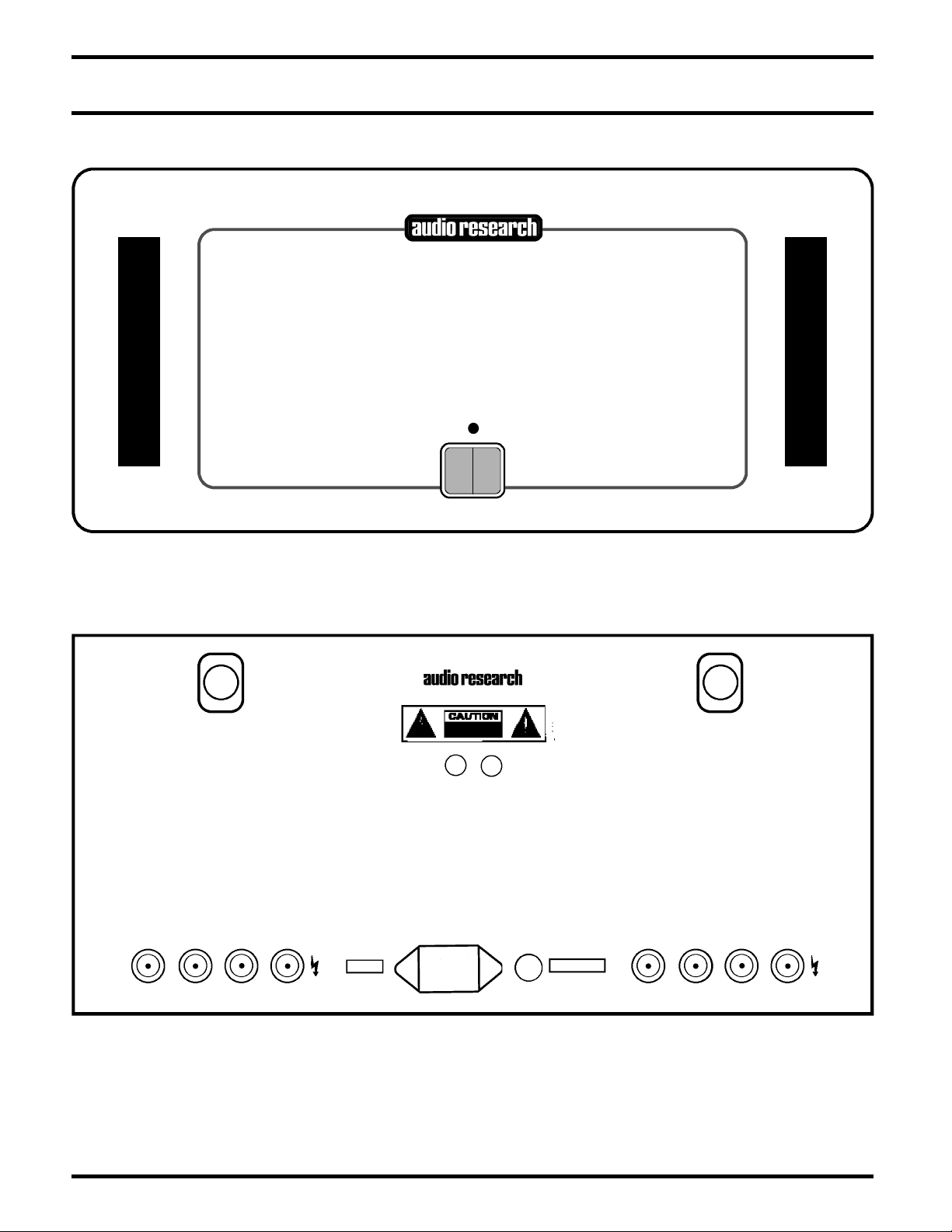
Model Reference 110
P O W E R
VACUUM TUBE
POWER AMPLIFIER
REFERENCE 110
HIGH DEFINITION
®
WARNING
TO PREVENT FIRE AND SHOCK HAZARD, DO NOT
EXPOSE THIS DEVICE TO RAIN OR MOISTURE.
UNIT MUST BE OPERATED IN A HORIZONTAL POSITION.
-DO NOT OPERATE WITH COVERS REMOVED -
UNIT CONTAINS VOLTAGES WHICH MAY BE HAZARDOUS
REFERENCE 110
S T ER EO A MP L I FI ER
VOLTS S E R I A L
PLYMOUTH, MINNESOTA
C A U T I O N
FOR CONTINUED PROTECTION AGAINST
FIRE HAZARD REPLACE FUSE ONLY
WITH SAME TYPE AND RATING
W A R N I N G !
RISK OF HAZARDOUS ENERGY!
MAKE PROPER SPEAKER CONNECTIONS
SEE OWNERS MANUAL
W A R N I N G !
RISK OF HAZARDOUS ENERGY!
MAKE PROPER SPEAKER CONNECTIONS
SEE OWNERS MANUAL
7A FUSE
SLO-BLO
T4A (230V)
800 W MAX
50 / 60 HZ
~
LEFT
INPUT
RIGHT
INPUT
4Ω 8Ω0Ω 16Ω4Ω 8Ω0Ω 16Ω
IN
+12V
REMOTE TURN ON
OUT
Page 4
Preface
Please take time to ca refully read and understand the
following instructions before you install or attempt to operate this equipment. Becoming familiar with the product
and its correct operating procedures will help assure you of
maximum musical enjoyment and reliable operation. The
effort you invest now will be well rewarded in the years
ahead
Packaging
Save all packaging accompanying this product. You have
purchased a precision electronic instrument, and it should
be properly cartoned any time shipment becomes necessary. It is very possible that this unit could be damaged
during shipment if repackaged in cartoning other than that
designed for it. The original packaging materials help protect your investment from unnecessary damage, delay and
added expense whenever shipment of this unit is required.
Accessories
1 – Phillips head screwdriver for cover removal
1 – Plastic screwdriver for bias adjustments
User replaceable spare fuses include:
1 – 7 Amp MDQ slo-blo with 120V units or 100V units
1 – T4A 250V slo-blo with 220V/240V units
Warnings
1. Do not touch hot tubes. Keep away from children.
2. To prevent fire or shock hazard, do not expose your
Reference 110 to rain or moisture.
3. This unit contains voltages which can cause serious
injury or death. Do not operate with covers removed.
Refer servicing to your authorized Audio Research dealer
or other qualified personnel.
4. The 12-gauge, 3-conductor detachable power cord on
your Reference 110 is equipped with a standard 3-prong
grounding plug. If used normally, it will provide a safe
earth ground connection of the chassis. Refer to the
sect i on on “AC Power Conn e ctions ” fo r detailed
information.
5. For cont i nued pr otect i on ag ai n s t fir e haz ar d,
replace fuses only with the same type and rating of fuses
as specified.
Warning!
Read Owner's Manual before installing or operating
this product!
Do not attempt to install or remove any vacuum
tubes unless this unit is turned off and disconnected
from the A.C. power outlet. Unit should be connected to the A.C. outlet and turned on only after all
vacuum tubes have been installed and appropriate
pa nel s hav e been r epla c ed and faste ne d . See
owner's manual for installation instructions.
Before replacing vacuum tubes, turn off unit, disconnect from A.C. outlet and allow installed tubes to
cool before attempting to remove them. Hot tubes
may cause burns or other injury if not allowed to
cool before removal.
When removing or installing tubes, do not touch tube
socket contacts or other components as the circuit
may retain sufficient levels of voltage and current to
cause injury or death.
Contact your dealer or Audio Research Customer
Service (763-577-9700) if you have any questions
about installing or replacing vacuum tubes in this
unit.
Model Reference 110
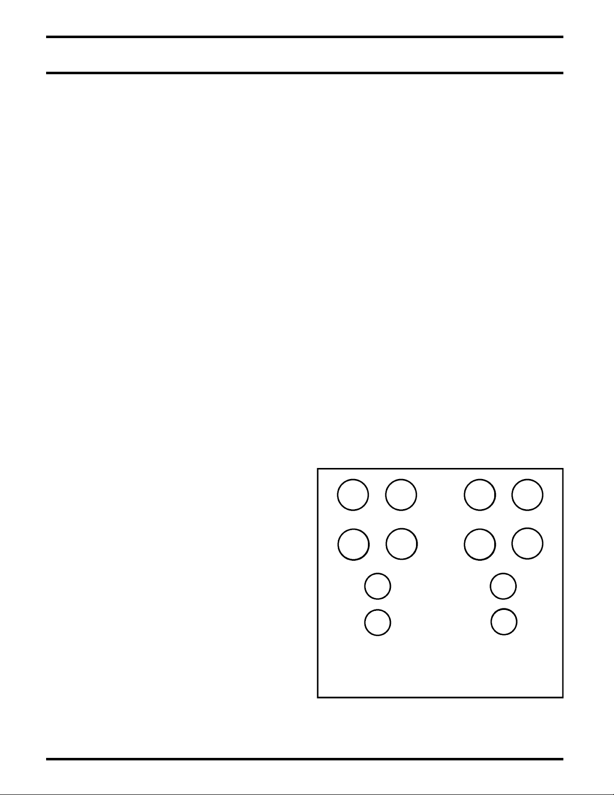
DO NOT ATTEMPT TO OPERATE THIS
EQUIPMENT BEFORE INSTALLING THE NUMBERED
VACUUM TUBES IN THEIR RESPECTIVE SOCKETS.
R E A R
F R O N T
V 7
V 5
V 9
V 3
V 2
V 1
V 4
V 12
V 6
V 10
V 8
V 11
(8)
6550C
(4)
6H30
TUBE LOCATIONS
TOP VIE W
1
Page 5

Vacuum Tubes and Preparation for Use
Your Reference 110 amplifier is shipped with the vacuum
tubes packed in foam blocks. These must be unpacked and
installed before you attemp t to operate the amplifier.
Included are four matched pair of 6550C output tubes, and
four 6H30 dual triodes used in the input stage. Proceed
according to the following instructions.
Carefully remove each vacuum tube from its protective
foam and match its location “V” number (written on the
base of the tube) to the “V” number printed next to each
socket. Firmly seat each tube in its matching socket, taking
care to “key” the tube pins to the socket holes. Retain the
foam blocks with other packing materials for possible
future use. Refasten top cover on amplifier.
Panel Controls
The front panel has:
1 – Switch: 1-Power line On-Off
1 – Indicator: 1 - Power "On" LED (Green)
Use of Controls
POWER-ON SWITCH: Initiates/terminates AC line power
to the amplifier. Function indicated by green LED above
switch.
N o t e : Audio Research does
n o t
recommend leaving your
Reference 110 “on” 24 hours a day as is the custom of some
audiophiles to achieve maximum sonic performance on demand. While this is often recommended for solid-state
equipment, Audio Research does not recommend this procedure for vacuum tube power amplifiers. (2,000 hours of
tube life will elapse in 84 days!)
Installation
To insure normal component life and safe operation this
unit must be op erated only in an uprig ht position
.
Adequate air flow and proper cooling can occur only if
there is no restriction above and behind the unit and on
either side. Be sure that airflow to the 12V D. C. cooling
fans located on the rear panel is not blocked.
The special non-marring elastomer feet provide adequate
spacing and stability only on a smooth, hard surface. F o r
upright stability, never operate the unit while it is sitting
on a soft surface such as a thick rug or carpet.
Due to its weight, this amplifier must be supported on a
surface specifically rated for such a load. Check with the
manufacturer of your support system to be sure it is rated
to handle this weight.
If the unit is to be operated in an enclosure such as an
equipment rack, make certain that adequate air flow above
and to each side of the unit is provided. The “ambient”
operating temperature should never exceed 120º F or 49º C.
Improper installation will cause premature tube failure and
will affect your warranty, as well as the service life of the
unit.
It is normal for a vacuum tube power amplifier to run quite
“warm”, and if used for prolonged periods, “hot” to the
touch. All components within are, however, operated at
safe, conservative levels and will not be improperly affected
thereby, providing the requirements outlined above are
adhered to.
Connections
INPUT CONNECTOR: The Reference 110 uses a fully bal-
anced circuit topology and has a pair of balanced XLR
input connectors on the rear panel. It therefore requires a
balanced preamplifier output, as provided by most Audio
Research preamplifiers. Connect your preamplifier's output
to the Reference 110 before turning on the amplifier.
OUTPUT CONNECTORS: Proprietary, heavy-duty output
terminals are provided on the rear panel for 4, 8,or 16-ohm
speaker imped ance loads. Using hig h-quality speaker
cables, securely fasten the (-) speaker lead to the appropriate (-) terminal, then the (+) lead to the matching (+) terminal. following your speaker manufacturer's impedance specification. The Reference 110 puts out the same amount of
power whether the 4, 8 or 16-ohm terminals are used.
IMPORTANT: Use the best available speaker wires and
interconnects. Audio Research cannot emphasize this
enough. As better components and systems are developed,
it becomes increasingly important to avoid the limitations
of inferior system interconnections.
It is important sonically that your entire system be
connected so that the audio signal arriving at the speakers
has correct, or “absolute” polarity (i.e., non-inverted).
Connect the black or “-” speaker terminal to the wire that
connects to the “0” terminal on the Reference 110. Connect
the red or “+” speaker terminal to the wire that connects to
the “4 ” or “ 8” terminal on the Reference 110. and tighten
the speaker terminals securely to ensure best sonic results.
MATCHING: It is important to use as close as possible an
impedance match between the amplifier and speaker for
optimum transfer of power to the speaker with minimum
distortion. In the case of speaker systems with significant
variations in impedance throughout the frequency spectrum, such as most electrostatic types, determine the best
impedance match empirically for best overall sonic results.
Connect the Reference 110 input to the preamplifier or
electronic crossover, using only the highest grade of audio
interconnect cables. To avoid sonic degradation use the
shortest practical length of cables.
Model Reference 110
2
Page 6

A.C. POWER CONNECTIONS: It is important that the
Reference 110 be connected via its supplied 20 amp IEC 12gauge power cord to a secure, dedicated A.C. power receptacle. Never connect to convenience power receptacles on
other equipment. Only use the power switch on the front
of the Reference 110 for On/Off control of the amplifier, or
the 12V start-up trigger for remote installations.
The AC power source for the Reference110 amplifier should
be capable of supplying 10 amperes for 100 or 120 volt
units, or 5 amperes for 220 or 240 volt units.
For the very best performance on domestic 100 or 120 volt
circuits, the Reference 110 should be connected to its own
AC power circuit branch, protected by a 15 amp breaker.
The preamplifier and other audio equipment should be
connected to a different power circuit and breaker.
The Reference 110 should be turned on a f t e r the other
com p onents of your sy stem. If th e Ref erence 110
is turned on before other components, the amplifier will
amplify any extraneous turn-on noises those components
might generate, which could potentially damage the loudspeakers. Good operating practice dictates that the ampli-
fier should be turned on last, and turned off first in an
audio system.
The Reference 110 uses a grounding system that does not
require a ground-lifter adaptor plug on the A. C. power cord
to minimize hum. T he power cord supplied with the
Reference 110 has a standard grounding plug to provide
maximum safety when properly connected to a grounded
wall receptacle. If there is any question regarding proper
grounding procedures in your installation, seek help from a
qualified technician. Caution should be taken before using
custom after-market power cords: they must be at least
12-gauge and have a standard grounding plug properly
installed. These power cords are to be used with caution, at
the sole risk of the owner.
If electronic crossovers or other AC powered equipment is
used with the Reference 110 it may be necessary to use
“ground lifter” adapters on the power plugs of that equipment to minimize system hum. Generally, the lowest hum
is achieved when the only direct connection between audio
common “ground” and true earth ground occurs in the
preamplifier, through its grounded power cord. Other
equipment in the system should have some form of isolation to prevent ground loops and associated hum.
Always place the power on-off switch on the panel
of the Reference 110 in the “O ff ” position before
connecting the power line cord to AC power.
Remote Turn-on Connections
The Reference 110 has a built-in 12VDC remote turn-on/off
circuit for operation by a master control system in a home
theater or large audio system. Use a 3.5mm (.140") diameter
mono mini plug to connect to the +12V IN jack on the rear
of the Reference 110. Two identical paralleled jacks are
provided to allow chaining connections to control two or
more Reference 110s or other equipment.
The +12V IN jack should be connected to the +12VDC
output of the master control system, using a continuous
+12VDC signal at 12mA per Reference 110 for the duration
of amplifier on-time. Do not use a momentary or data pulse
control signal.
The front power rocker switch on the Reference 110 must
be off to use the remote turn-on. The front power rocker
switch may still be used when the remote turn-on is connected, but the remote will not turn the Reference 110 off
if the front power rocker switch is left on. The front power
rocker switch will not turn the Reference 110 off if the remote system is on.
The +12VDC remote jacks have polarity protection, so they
will not operate if a -12VDC signal is accidentally connected, or if the control wires are reversed. The 12V remote
relay in the Reference 110 has click suppression to protect
circuits in the master control system.
Operating Procedure
Start-Up:
1. Secure input connection between the amplifier and your
preamplifier; attach speaker leads to the appropriate
output terminals.
2. Attach supplied power cord to rear IEC inlet of amplifier,
and plug other end into grounded A. C. power receptacle.
3. Turn on preamp and all other components; mute preamp
output.
4. Turn Reference 110 front-panel control from Off to
On. Green power LED will light.
5. Unmute preamplifier output, initiate source component
signal, and adjust gain as appropriate.
Shut-Down:
1. Mute preamplifier output.
2. Turn Reference 110 front-panel control from Operate to
Off.
3. Turn off preamplifier and then the associated input
source components.
Warning!
After the Reference 110 is turned off, wait at least 5
minutes before turning it on again.
Model Reference 110
3
Page 7

Output Tube Bias Adjustment
As shipped from t he fact o ry, th e outp u t “bia s ”
adjustments are set for a nominal 65mA per 6550 tube.
Under these idle conditions the tubes are each dissipating
app r oximat ely 27 w a tts of t heir 48 watt ratin g (4 2
watt plate, 6 watt screen). This point of operation provides
“enriched” Class AB
1,
and will satisfy the most critical
listener.
For best results, operate and adjust the Reference110 at
120VAC. Adjustment must be made under zero-signal
conditions after at least 15 -20 minutes of uninterrupted
stabilization time.
A digital voltmeter capable of accurate measurements with
0.lmVDC resolution is preferred for accurate adjustment
(must have 31/2digit display). Use the plastic alignment
tool provided to make the adjustment. The measurement
points are yellow and black banana test jacks next to each
output tube. Adjust the “bias” for a voltage reading of
65mVDC (.065 Volt DC) at the blue bias pot for one of each
output tube pair as follows, noting the voltage setting of
the larger V number tube in each pair is slaved to the
adjustment setting of its lower V number companion tube:
Adjust V5 for 65mVDC and measure its companion tube
V7 to verify a reading of 57 to 73mVDC. Repeat procedure
by adjusting and measuring V9 to read 65mVDC and verify
V11 reads 57-73mVDC; adjust and measure V6 to read
65mVDC and verify V8 reads 57-73mVDC, and finally
adjust and measure V10 to read 65mVDC and verify that
V12 reads 57-73 mVDC.
Cooling Fan Speed Adjustment
The two D.C. cooling fans located at the rear of the
Reference 110 are adjustable in speed. Locate the red
colored dip switch under the top cover at the top near the
center of the back panel. For highest fan speed move both
white tabs on the red dip switch to the upward position;
for medium fan speed move either one of the tabs to the
downward position, and for low fan speed move both tabs
to the downward position. For maximum cooling and
extended tube life, use the highest fan speed possible. Be
sure to first turn off and unplug the Reference 110 from
its power receptacle before unscrewing the top cover to
access the switch. Refasten the top cover before resuming
operation. Do not operate the Reference 110 with fans
disconnected or if one or both fans should stop running.
Hour Meter
An LCD hour meter of elapsed tube operating time can be
viewed through the top cover near the front, mounted on
the right main circuit board. Displays accumulated hours of
vacuum-tube service life. If the amplifier is unplugged from
A.C. supply, total accumulated hours are retained. May be
reset by qualified technician. Contact Audio Research Customer Service for more information about reset procedure.
Servicing
Because of its careful des ign a nd exacting standard s
of man ufacture, your Reference 110 amplifier sh ould
normally require only minimal service to maintain its high
level of performance.
CAUTION: The Reference 110 amplifier contains sufficient
levels of voltage and current to be
l e t h a l
. Do not tamper
with a component or p art inside the unit. Even with
the power turned off, a charge remains in the energy
storage capacitors for some time. Refer any needed service
to your authoriz e d Audi o Resear ch dealer or o ther
qualified technician.
Additional questions regarding the operation, maintenance
or servicing of your amplifier may be referred to the
Customer Service Department of Audio Research Corporation at 763-577-9700 ( C S T). When ordering a service
manual from Audio Research or an authorized dealer, be
sure to identify the serial number on your amplifier.
Cleaning
To maintain the new appearance of this amplifier, occasionally wipe the front panel and top cover with a soft, damp
(not wet) cloth to remove dust. A mild, non-alkaline soap
solution may be used to remove fingerprints or similar
smudges. Cleaners containing abrasives should
not
be used
as they will damage the anodized finish of the front panel.
A small, soft paint brush is effective in removing dust from
bevels, the recessed nameplate and other features of the
front panel.
Disposal and Recycling Guidelines
To dispose of this electronic product, do not place in landfill. In accordance with the European Union Waste Electrical and Electronic Equipment (WEEE) directive effective
August 2005, this product may contain regulated materials
which upon disposal require special reuse and recycling
processing.
Please contact your dealer or importing distributor for
instructions on proper disposal of this product in your
country. Or, contact Audio Research Corporation (763-577-
9700) for the name of your importing distributor and how
to contact them.
Packing and shipping materials may be disposed of in a
normal manner.
Model Reference 110
4
Page 8

Limited Warranty
Audio Research Corporation products are covered by a
3-Year Limited Warranty or a 90-Day Limited Warranty
(vacuum tubes). This Limited Warranty initiates from the
date of purchase, and is limited to the original purchaser, or
in the case of demonstration equipment, limited to the
balance of warranty remaining after original shipment to
the retailer or importer.
In the United States, the specific terms, conditions and
remedies for fulfillment of this Limited Warranty are listed
on the warranty card accompanying the product in its shipping carton, or may be obtained from the authorized
retailer or from the Audio Research Customer Service
Department. Outside the United States, the authorized
importing retailer or distributor has accepted the responsibility for warranty of Audio Research products sold by
them. The specific terms and remedies for fulfillment of
the Limited Warranty may vary from country to country.
Warranty service should normally be obtained from the
importing retailer or distributor from whom the product
was purchased.
In the unlikely event that technical service beyond the ability of the importer is required, Audio Research will fulfill
the terms and conditions of the Limited Warranty. Such
product must be returned at the purchaser's expense to the
Audio Research factory, along with a photocopy of the
dated purchase receipt for the product, a written description of the problem(s) encountered, and any information
necessary for return shipment. The cost of return shipment
is the responsibility of the purchaser.
Specifications
POWER OUTPUT: 110 watts per channel continuous from
20Hz to 20kHz. 1kHz total harmonic distortion typically 0.3%
at 110 watts, below 0.03% at 1 watt.
Approximate actual power available at “clipping” 120 watts
(1kHz). (Note that actual power output is dependent upon
both line voltage and “condition” i.e.: if power line has high
distortion, maximum power will be affected adversely, although
from a listening standpoint this is not very critical.)
POWER BANDWIDTH: (-3dB points) 12Hz to 60kHz.
FREQUENCY RESPONSE: (-3dB points at 1 watt)
0.6Hz to 90 kHz.
INPUT SENSITIVITY: 1.8V RMS BAL for
rated output. (24 dB Bal gain into 8 ohms.)
INPUT IMPEDANCE: 300K ohms Balanced.
OUTPUT POLARITY: Non-inverting. Balanced input pin 2+
(IEC-268).
OUTPUT TAPS: 16 ohms, 8 ohms, 4 ohms.
OUTPUT REGULATION: Approximately 0.7dB 16 ohm load
to open circuit (Damping factor approximately 12).
OVERALL NEGATIVE FEEDBACK: 12dB.
SLEW RATE: 10 volts/microsecond.
RISE TIME: 3.5 microseconds.
HUM & NOISE: Less than 0.2mV RMS – 106dB below rated
output (IHF weighted, input shorted).
POWER SUPPLY ENERGY STORAGE: Approximately 520
joules.
POWER REQUIREMENTS: 105-125VAC 60Hz (210-250VAC
50Hz) 630 watts at rated output, 800 watts maximum, 410
watts at “idle”.
TUBES REQUIRED: 4 – Matched pair 6550C – Power
Output; 4 – 6H30 Driver.
DIMENSIONS : 19" (48.3 cm) W x 8.75" (22.2 cm) H x 19.5"
(49.5 cm) D. Handles extend 1.5" (3.8 cm) forward.
WEIGHT: 67.4 lbs. (30.7 kg) Net; 83.0 lbs. ( 37.8 kg ) Shipping.
Specifications subject to change without notice.
©2006 Audio Research Corporation.
5
Model Reference 110
 Loading...