

Audio Refinement Pre 2-DSP Owners manual
OWNER INFORMATION
Pre-2DSP Preamp-processor
Precision
Innovation & Musicality
by
Audio Refinement

PRE-2DSP PREAMP-PROCESSOR
ACKNOWLEDGMENT & TRADEMARK
2

TABLE OF CONTENTS
Pre-2DSP
PreAmp-Processor
INTRODUCTION ..................................................................................................
DESIGN PHILOSOPHY ........................................................................................
UNPACKING AND INSPECTION ........................................................................
CARE USE ........................................................................................................
FRONT PANEL FUNCTIONS ...............................................................................
REAL PANEL FUNCTIONS .................................................................................
REAL PANEL CONNECTIONS ............................................................................
CONNECTIONS OF PRE-2DSP .............................................................................
REMOTE CONTROL ............................................................................................
SPECIAL RECOMMENDATIONS AND NOTICE ITEMS ....................................
OPERATION .........................................................................................................
LCD DISPLAY AND INDICATORS .............................................................
INPUT SOURCE SELECTION .....................................................................
AUDIO AND VIDEO INPUT EXPLANATIONS ..........................................
RC-5 REMOTE COMMANDS CODE ......................................................
OSD (ON-SCREEN DISPLAY) .....................................................................
MASTER VOLUME CONTROL ...................................................................
BALANCE SETTING ...................................................................................
MUTE MODE ..............................................................................................
TEST A/M MODE ........................................................................................
SOUND FIELD PROCESSING .....................................................................
SPEAKER PLACEMENT .............................................................................
DELAY CALIBRATION ...............................................................................
TIME DELAY ADJUSTMENT ON CENTER CHANNEL SPEAKER ...........
TIME DELAY ADJUSTMENT ON SURROUND SPEAKER ........................
BASS CROSSOVER NETWORK SETTING .................................................
SPEAKER MODE WITH BASS MANAGER ................................................
PROLOGIC MODE .....................................................................................
SAVING PRESETS ......................................................................................
LOADING PRESETS ....................................................................................
BYPASS SETTING .......................................................................................
TAPE MONITOR ..........................................................................................
EQUALIZATION ..........................................................................................
RESETTING .................................................................................................
DRC (DYNAMIC RANGE COMPRESSION) ...............................................
TROUBLESHOOTING...........................................................................................
SPECIFICATIONS ................................................................................................
RECOMMENDATIONS .........................................................................................
4
4
4
4
5
6
7
8
10
11
11
12
12
12
13
14
15
15
15
16
16
17
17
18
18
19
19
20
21
21
21
22
22
22
22
23
23
24
Record the following information for future reference
Serial Number
Dealer Name
:
:
Purchase Date
Dealer Phone Number
3
:
:
:

INTRODUCTIONINTRODUCTION
Audio Refinement was conceived to offer the renowned musicality or "sonic signature" of YBA
Electronics by Yves-Bernard ANDRE' in a more affordable range of products. It benefits from the
same design philosophy and attention to minute detail that is the hallmark of YBA.
Thank you for your purchase of the Audio Refinement Pre-2dsp, pre/processor. It is precisely crafted
innovatively designed and extremely reliable. We appreciate your faith in our products and we trust
that your Pre-2dsp will reward you with many years of audio/video pleasure.
Please read the operating instructions before connecting the Pre-2dsp to your audio/video system.
DESIGN PHILOSOPHYDESIGN PHILOSOPHY
An important design goal for Audio Refinement is the control of parasitic vibrations. These mechanical vibrations in the air have a negative effect on the purity of sound. The impact of these
vibrations depends on the size of the audio equipment, the internal components and the rigidity
of the construction. The solutions chosen for Audio Refinement include:
The mechanism is designed to be as compact and as rigid as possible. The small physical size of
your Audio Refinement Pre-2dsp moves the resonant frequencies out of the audio domain.
The PRE/PROCESSOR has only 3 feet which is the ideal way to drain vibrations.
The transformer is suspended to reduce the transmission of its vibrations to the rest of the circuitry.
The choice of materials is also an important part of the design of your Audio Refinement Pre-2dsp,
the bottom is made of non-magnetic aluminum, the other parts are brushed and colored
aluminum.
UNPACKING AND INSPECTIONUNPACKING AND INSPECTION
Carefully unpacking your Pre-2DSP and locate the enclosed accessories:
RC-DSP Remote Controller with AA batteries
Detachable AC Cord
Remote Connection cord
Owner's Information
CARE & USECARE & USE
Ensure that your main AC voltage matches the voltage marked on the rear of the unit and on the
exterior of the shipping carton.
To avoid damage to your Pre-2dsp, we recommend that you disconnect the AC during electrical storm or if the unit will be unused for an extended period of time.
Do not handle your AC cord with wet hands. If liquid spills on your Pre-2dsp, unplug immediately
and contact your dealer for cleaning instructions.
Do not remove the top cover of your Pre-2dsp or attempt to modify any circuitry. This will void your
guarantee and could result in serious injury.
Always turn the Pre-2dsp off before making any connections. Ensure that the speaker cables of
your power amplifier do not touch each other. A short circuit will damage the unit and is not
covered under the guarantee!
Keep your Pre-2dsp out direct sunlight. Because it could interfere with the remote control sensor.
Keep the Pre-2dsp away from heat sourcres such as hot air ducts, radiators and moistures sources
such as open windows.
4
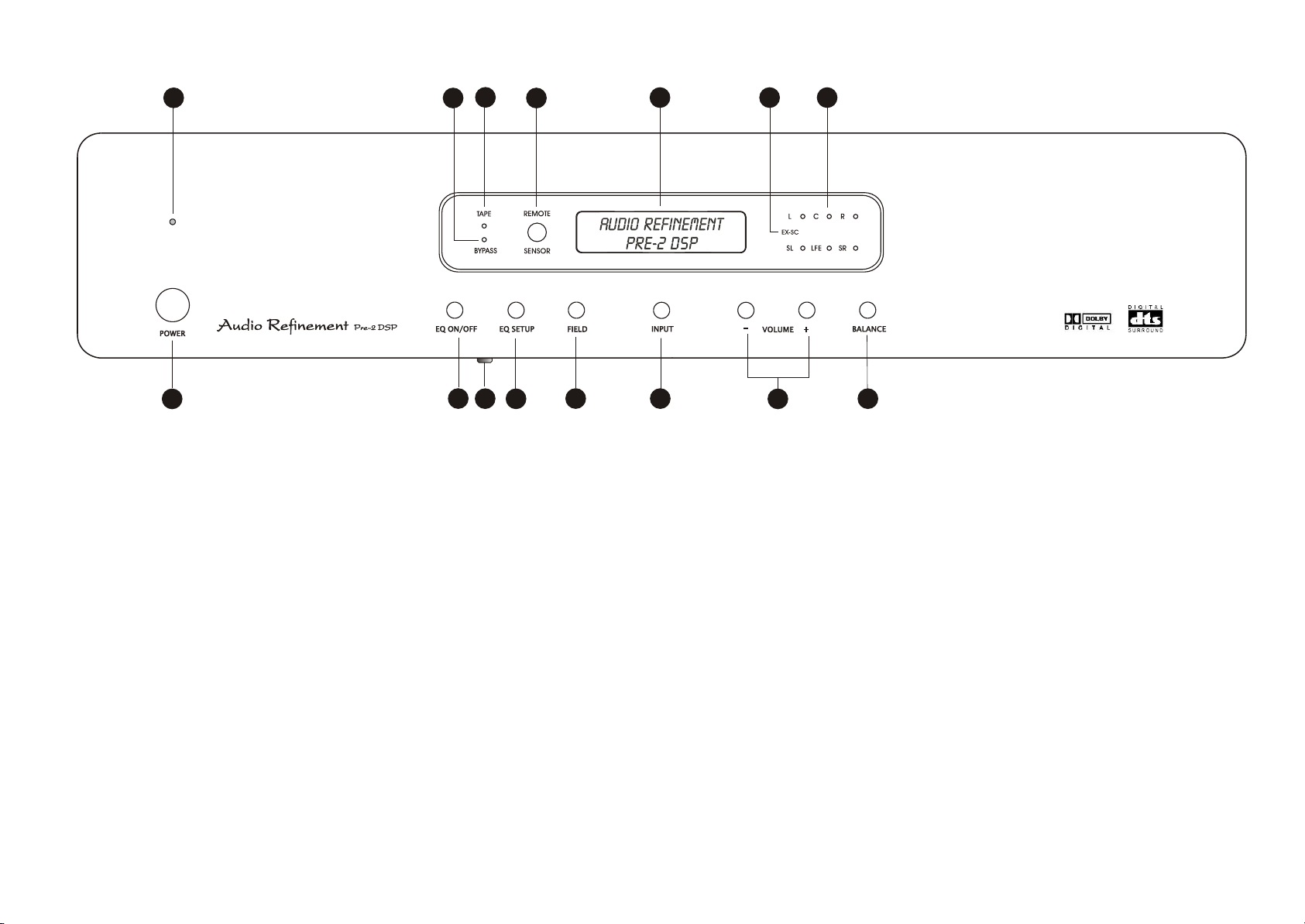
FRONT PANEL FUNCTIONSFRONT PANEL FUNCTIONS
9
1
1. POWER Button1. POWER Button
This button to turns ON or STANDBY Pre-2DSP.ON STANDBY
2. EQ ON/OFF Button2. EQ ON/OFF Button
Activate the selected EQ band setting
3. REC ON/OFF Button
3. REC ON/OFF Button
Press this button will be on and press again will be off.
4. EQ SETUP Button
4. EQ SETUP Button
Select up to 5 EQ band settings.
5. FIELD Button
5. FIELD Button
Select among 6 different sound fields
6. INPUT/SELECT Button
6. INPUT/SELECT Button
Select different source inputs.
Select the length of Delay time for SL/SR/C channels.
Select the length of Balance for L/C/R/SL/SR/LFE channels.
Select the length of Test/M for L/C/R/SL/SR/LFE channels.
Select up to 5 EQ Band +/- adjusts.
bass
Select bass crossover (80Hz, 90Hz, 100Hz, 110Hz, 120Hz)
Delay
Balance
Test/M
EQ Band
10
11
2
3
12
4
7. VOL/ADJUST Button
7. VOL/ADJUST Button
8. BALANCE Button
8. BALANCE Button
5
Increase/decrease the Volume level.
Increase/decrease the Delay times.
Increase/decrease the Balance level.
Increase/decrease the EQ level.
First press this button then press vol button to set
5CH output volume.
Custom set the volume setting for 6 channels.
13
6
14
7
Volume
Delay
Balance
EQ
15
8
12. REMOTE Sensor12. REMOTE Sensor
This sensor receives a signal from the remote
handset.
13. LCD Display13. LCD Display
This display provides you with important
information regarding system status and
settings.
It is important to be familiar with all the
indications on the display in order to have the
system function properly.
14. EX-SC Indicator14. EX-SC Indicator
9. POWER Indicator 9. POWER Indicator
This red color LED lights up when STANDBY.
This green color LED lights up when POWER ON.
STANDBY.
POWER ON
10. BYPASS Indicator 10. BYPASS Indicator
This red color LED lights up when Bypass ON.Bypass ON.
11. TAPE Monitor Indicator 11. TAPE Monitor Indicator
This green color LED lights up when Tape
Monitor ON.
Monitor ON.
5
Tape
UP-GRAGE for EX 6.1.
15. Speaker Configuration LEDs15. Speaker Configuration LEDs
Each LED represents the status of an individual
channel. When a particular channel is active,
the LED LIGHTS UP. Red color LED light means
this particular channel has been set to output
a wider frequency range that contains bass
signal between 20Hz to 120Hz.
Green color LED light means this particular
channel doesn"T contain the bass signal
between 20Hz to 120Hz.
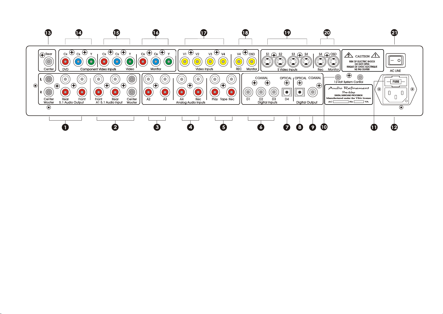
REAL PANEL FUNCTIONSREAL PANEL FUNCTIONS
1. 5.1 Audio Output1. 5.1 Audio Output
The Pre-2DSP provides a stereo output pair for the Left and
Right front and Surround speakers, a single monaural
output for the Subwoofer, and a single monaural output
for the center Speaker. Connect these outputs to inputs of
your power Amplifiers.
2. A1 5.1 Audio Input2. A1 5.1 Audio Input
The 5.1 Analog audio Input connections accept six
channels of processed analog output of a DVD player or
DVD Audio player or processor with discrete outputs.
Connect the six discrete outputs of your source
component to the corresponding 5.1 Analog inputs of the
Pre-2DSP.
3. A2, A3 Analog Audio Inputs
3. A2, A3 Analog Audio Inputs
Two Analog Audio inputs are compatible with typical
andlog line level sources. Connect the left and right
analog audio output of your audio source componets to
any of these two analog audio inputs.
4. A4. REC Analog Audio Inputs
4. A4. REC Analog Audio Inputs
Analog Audio input. It can connect to a VCR`S audio
outputs.Analog Audio record output for VCR recording. It
can connect to a VCR`s audio outputs.
5. Tape (Monitor) Play / Rec
5. Tape (Monitor) Play / Rec
Connect the TAPE Monitor PLAY / REC jacks to the PLAY(Line
out) / REC(Line in) jacks of a tape deck or MD recorder.
6. D1, D2, D3 COAXIAL Digltal Inputs
6. D1, D2, D3 COAXIAL Digltal Inputs
These three sockets all coaxial digital inputs.
7. D4 Optical Digital Input7. D4 Optical Digital Input
This is optical digital input jacks.
8.9. Optical & Coaxial Digital Output8.9. Optical & Coaxial Digital Output
Connect the 75 optical or coaxial digital record outputs
to the digital input of your digital recording component.
10. 12V System Control10. 12V System Control
These jacks Outputs provide +12 Volt DC trigger to
activate equipment such as power amplifiers or relays.
Connect these outputs to the DC input of the component
you want to activate.
11. AC Fuse11. AC Fuse
220V 50Hz 3.15A , 117V 60Hz 3.15A , slow-bow
12. AC Line Cord Receptacle12. AC Line Cord Receptacle
Use the supplied power cord to connect the Pre-2DSP to
a wall receptacle.
13. Rear Center Output13. Rear Center Output
UP-GRAGE for EX 6.1.
14. Rear Center Output14. Rear Center Output
Component video input connect this jacks to the
component video out of DVD player or any video.
15. Component Video Input15. Component Video Input
Connect this jacks to the component video out of second
DVD player or any video player.
6
16. Component Video Output16. Component Video Output
Connect this jacks to the component video in of the TV
monitor.
17. Video Input17. Video Input
V1~V4 all are video input jacks connect any of them to
the video out of DVD player or any video player.
18. V4/Rec and OSD/Monitor18. V4/Rec and OSD/Monitor
V4 is composite video output, connect this jacks to the
video in of DVD player or any video player for video
recording, OSD monitor jacks is also a composite video
output, connect this jacks to the video in of your TV
monitor for the function of Pre-2DSP can splay on the
screen.
19. S-Video Input19. S-Video Input
S1~S4 all are S-video input jacks, connect any of them to
the S-video output of DVD player or any video player.
20. S4/Rec and OSD/Monitor20. S4/Rec and OSD/Monitor
S4 is a S-video output jacks, connect this jacks to the Svideo in of DVD player or any video player for recording,
S-OSD monitor jacks is a S-video output jacks, connect this
jacks to the S-video in of DVD player or any video player
for the function of Pre-2DSP can display on the screen.
21. Main AC Switch21. Main AC Switch
This is the main power switch for the Pre-2DSP, in the off
position, all function are disabled, including the front
power switch.
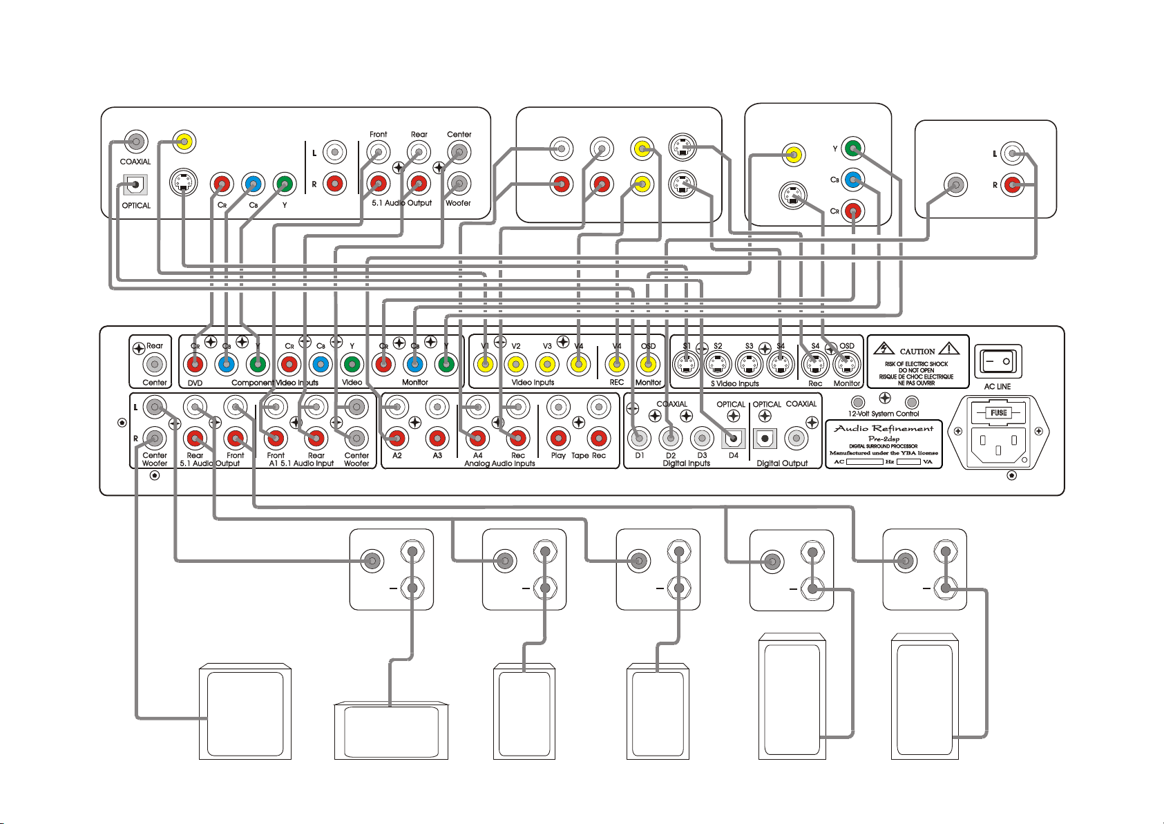
REAL PANEL CONNECTIONSREAL PANEL CONNECTIONS
Digital OutDigital Out
DVD/Video PlayerDVD/Video Player
CompositeComposite
Video OutVideo Out
S-Video OutS-Video Out
ComponentComponent
Video OutVideo Out
DVD/Audio PlayerDVD/Audio Player
StereoStereo
Audio OutAudio Out
Video Cassette RecorderVideo Cassette Recorder
AudioAudio AudioAudio VideoVideo
LL
InIn
RR
Play/OutPlay/Out Rec/InRec/In
OutOut
S-VideoS-Video
InIn
OutOut
TV MonitorTV Monitor
CompositeComposite
Video InVideo In
S-Video InS-Video In
ComponentComponent
Video InVideo In
CD Player/TransportCD Player/Transport
AudioAudio
Coaxial DigitalCoaxial Digital
OutputOutputOutputOutput
SubwooferSubwoofer
InputInput
++
CenterCenter
AmplifierAmplifier
LFE SpeakerLFE Speaker Center SpeakerCenter Speaker
InputInput
++
InputInput
++
InputInput
++
InputInput
++
LSLS RSRS LL RR
AmplifierAmplifier AmplifierAmplifier AmplifierAmplifier AmplifierAmplifier
Left SurroundLeft Surround Right SurroundRight Surround Right SpeakerRight SpeakerLeft SpeakerLeft Speaker
7

CONNECTIONS OF PRE-2DSP
1. 5.1 Audio Output
a. Center Channel Output
Connect the Center channel output of your Pre-2DSP to the input of a mono amplifier or to
the channel of the multi-channel amplifier that is connected to your center (C) speaker.
b. Subwoofer Output
Connect the subwoofer output of your Pre-2DSP to the input of active subwoofer.
c. Left and Right Rear Channel Outputs
Connect the Left and Right rear outputs of your Pre-2DSP to the input of the two channel amplifier
or to two channels of a multi-channel amplifier that are connected to your left and right surround
(LS, RS) speakers.
d. Front Left and Right Channel Outputs
Connect the Left and Right Front channel outputs of your Pre-2DSP to either the inputs of a two
channel amplifier or to two channels of a multi-channel amplifier that are then connected to your
main front left and right (L, R) speakers.
2. 5.1 Analog Inputs
The 5.1 Analog Input are designed to accept up to six channels of processed analog output from
a DVD player or DVD Audio player other component with discrete outputs. Connect the six discrete
outputs of your source component to the corresponding 5.1 Analog Input of the Pre-2DSP.
3. A2 A3 Analog Audio Input Connections
The A2 A3 analog inputs are compatible with typical analog line level sources such as CD players,
MiniDisc players, cassette decks, etc. connect the left and right analog audio outputs of your
audio/video source components to these inputs.
4. A4 Input and Rec (Record and Playback) Connections
Use the A4 inputs and outputs for the VCR you intend to use to record the picture and sound. The
signal present at the V4 Record output sends analog audio from whichever of the other A2 A3
V2 V3 Audio/Video or Audio-only inputs you select.
1. Connect the left and right audio output connectors from the VCR you'll use for recording
to the A4/V4 Input connectors of the Pre-2DSP.
2. Connect the left and right A4 REC (Record) Output connectors of the Pre-2DSP to the left
and right audio input connectors of the VCR.
3. Connect the composite video output connector of your VCR to the V4 or S4 input of the
Pre-2DSP and connect the V4 REC or S4 REC Composite Record Output connectors of the
Pre-2DSP composite video input connectors of the VCR.
5. Tape monitor play and REC Connections
The audio signal from the source you selected for the main zone is routed to both pairs of Record
Output connectors. Connect the lift and right play/output of your tape deck to the left and right of
any of the Pre-2DSP's A2 A3 A4 input connectors. Next, connect the left and right audio
record/input connectors of your tape deck to either pair of Left and Right channel Record Output
connectors of your Pre-2DSP.
6. Digital Audio Input Connections
Your Pre-2DSP has four digital input connections: three Coax RCA jack, one Optical Toslinks.
a. Coaxial Digital Inputs
The four Coax Inputs on the Pre-2DSP accept a standard S/PDIF digital bitstream form any CD
player, DVD player, DSS receiver, or other digital component equipped with a 75
8
 Loading...