

12#x#12#DIGITAL#AUDIO#MATRIX!
ZONIX 1212
USER MANUAL
2!2!
Safety Instructions
READ CAREFULLY THE FOLLOWING INSTRUCTIONS
POWER SUPPLY
Connect the appliance only on a current corresponding to the characteristics listed in the back of the device.
Failure to observe this precaution could result in fire or electric shock, or a failure not covered by the warranty.
POWER CORD
Before using the appliance for the first time, check that the supply voltage is consistent with that of the sector.
Before connection to the mains check that the power cord is properly plugged. Route the power cord so that it
cannot be squashed or bent and keep it away from moisture and significant heat sources. In case of
deterioration or failure please contact dealer to replace it with an identical cord. A damaged cord may result in
fire or electric shock.
PROTECTIVE GROUND
The appliance must be connected to the ground, don't remove the ground wiring of the power cord connector.
HUMIDITY
Do not expose the unit to rain or moisture and do not place container containing a liquid that might tip over. Do
not handle any connector with wet hands. In case of thunderstorm, turn the unit off and disconnect it from any
power outlet.
HEAT
Do not install the unit in a place subject to excessive heat or direct radiation from the Sun. Operating ambient
temperature must not be below 5 ° C (41 ° F) or above 35 ° C (95 ° F).
DAMAGE
Unplug immediately in the event of introduction of liquids or objects in the device as well as in the event of
damage to the power cable. Also unplug the unit if it emits smoke, an odor, or unusual noise. Then contact a
dealer or a Service Center authorized by Audiopole.
DISPOSAL
This symbol indicates the presence of a dangerous voltage.
This made symbol refers to information in the instructions manual.
This symbol indicates that the disposal of this product is submitted to local regulations. Please
contact your local dealer.

3!
1. Introduction …………………………………………………………………………………….. 4
2. Main Features………………………………………………………………………………...… 4
3. Description ……………………………………………………………………..…………..….. 4
A. Front Panel…………………………………………………………..…………….…. 4
B. Rear Panel ……………………………………………………..……….…………… 5
4. Software………………………………………...……………….…………………................... 6
5. Menu Bar…….………….…………………………………………………….……………….… 7
1. File……………………………………………………….…………….………………. 7
2. Local Settings…………………………………………….………….……………….. 7
a. RC Panel Configuration…………………….……………….………..….. 7
b. Channel Setting………………………………….……………………...... 7
c. Device List …………………………………….……………….………….. 8
d. Connect………………………………….………………..………............. 8
e. Disconnect………………………………….………………….…………... 8
f. Center Control Command ……………….………………………………. 9
3. Device Settings ………………………………………………………………………. 10
a. User Manager ……………..…………………………..………………….. 10
b. Serial Settings …………………………………………………………….. 11
c. Network Settings ……………………………………………................... 11
d. Scene Manager …………………………………………….…………….. 12
e. Voice tracking …………………………………………………...………... 13
f. GPIO Setting …………………………………………………..…………. 15
4. Help ……………………………………………………………………….…………… 20
a. Content ……………..…………………………………..………………..... 10
b. About ………………………………………………….…………………... 11
6. Inputs ……………………………………………………………………….…….…………..… 21
1. Creating Groups of Inputs…………………………………………..…..………….. 22
2. Manage the Position of the Faders……………………….……………………….. 22
3. Input Parameters ………………………………………………………………..….. 23
4. Expander / Gate …………………………………………………………………...... 24
5. Parametric EQ……………………………………………………………………….. 25
6. Compressor ………………………………………………………………………….. 26
7. Automatic Gain Control (AGC) …………………………………….....………….... 27
8. Scene Manager and GPIO ……………………………………………………….... 28
9. Ducker ……………………………………………………………………………….. 29
10. SPL (Ambient Noise Controller) …………………………………………………... 30
7. Outputs …………………………………………………………………………………….…… 31
1. Source ……………………………………………………………............................ 32
2. Speaker Manager …………………………………………………………………… 32
3. Limiter ………………………………………………………………………………... 33
4. Output Level …………………………………………………………………………. 34
8. Technical Features …………………………………………….….………………………….. 35
9. Warranty ………………………………………………….……………………….……………. 36
Index
Introduction
4!
Thank you for your purchase of the AUDIOPOLE ZONIX 1212. This very powerful processor offers many
possibilities thanks to its flexibility and its technology. Controlled by a 64 bits DSP, the features of this matrix
are numerous and can be used or not depending on the applications. Providing 12 inputs and 12 outputs, the
ZONIX 1212 delivers the most efficient price/quality. With a very intuitive user interface, the management of
complex areas becomes easy.
1
• 12 analog inputs , 12 analog outputs
• 16 GPIO
• 64 bits DSP platform
• 24 bits A/D-D/A 48 kHz to 96 kHz
• RS 232 bidirectional, RS 485
• M-LAN multi-purpose data transmission and control port
• Adaptive PoE external panel control interface
• Input modules:
Pre amp; sine wave, white and pink noise generator; Gate / Expander; 5 bands parametric EQ; AGC
(Automatic Gain Control); Compressor; Ducker; ANC (Ambient Noise Controller).
• Output modules:
8 bands Parametric EQ, HPF, LPF, Delay
• Voice tracking
Main features
2
1
2
3
4
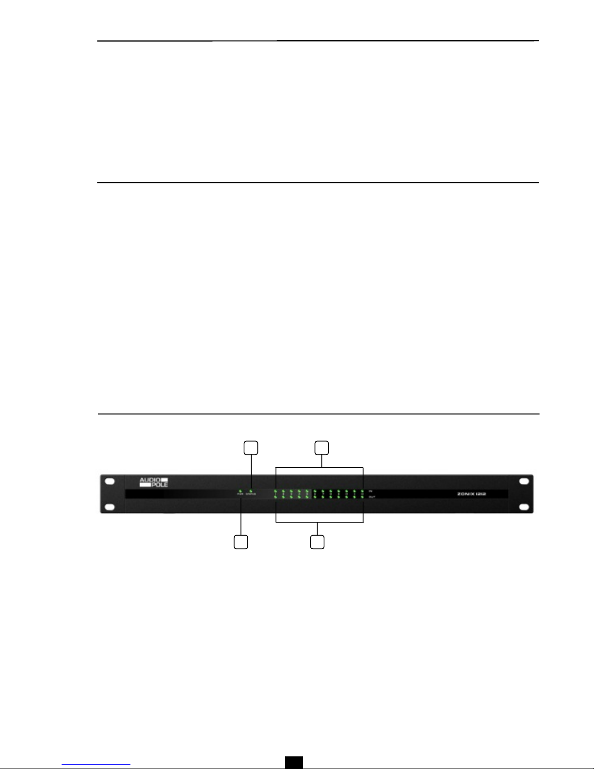
1 – POWER
Power indicator.
2 – STATUS
When the system run normally the indicator is flickering, it stays ON during upgrading.
3 – IN
Individual input signal indicators: It illuminates green when a signal is present and red when the channel is
switched off (MUTE).
4 – OUT
Individual indicators of output signal: It illuminates green when a signal is present and red when the channel is
switched off (MUTE).
A – Front panel
Panel layout
3
Description
3
5
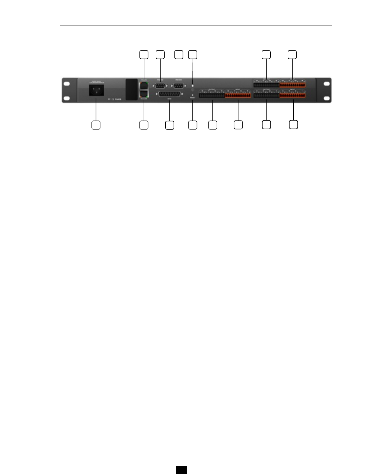
B – Rear Panel
5 7
6 8 9
10
11
12
13
14
15
16
17 18
5 – POWER
Power socket: accepts voltages from 100V ~ 240V, 50 ~ 60 Hz.
6 – M-LAN
Network interface, to connect PC: on-line editing and command, receiving and sending control.
7 – RC-LINK
External control panel interface, to connect RC panels via the network cable.
8 – RS232
Bidirectional communication interface to connect external central control equipment. Support camera tracking.
9 – RS485
Communication interface. Support camera tracking.
10 – GPIO
8 inputs / 8 outputs GPIO DB25 socket.
11 – RESET
System reset button.
12 – Ground
Ground connection.
13, 15, 17 – OUT
Analog audio output sockets.
14, 16, 18 – IN
Analog MIC/LINE input sockets.
Sotware Inctructions
4
6
The software is compatible with Windows XP, Vista, Windows 7 and Windows 8. Before installing the software,
verify that "NET Framework 3.5" is installed in the computer. Also check the compatibility of the network with the
IP address of the device defined by default (192.168.10.10).
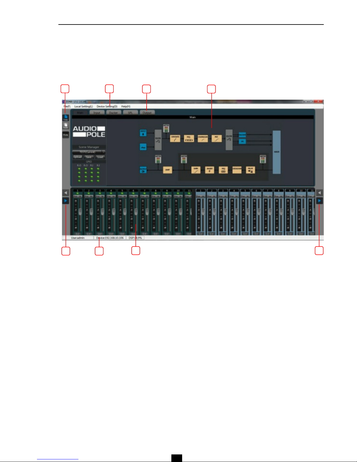
Once properly installed software the following screen is displayed as shown in figure below.
1 – Menus and tool bars
The menu bar contains the main software functions and the toolbar underneath displays processing modules
options.
2 – Copy / Paste!
Copies of the parameters of a module to another similar module. Click on the module to copy, it is framed in
red, click on Copy, select another module, and then click Paste.
3 – Processing modules control zone
At the software start, this area shows the functional diagram of the matrix. After making a selection in the
toolbar, this box displays one or more processing modules for each channel.
4 – Control of the inputs / outputs
Displays the gain, level and mute for each inputs / outputs.
5 – Functions and non-visible channel
The processing modules in the box (3) correspond to the last channel being clicked; to view channels hidden
on the screen, use the arrow keys left and right. When a channel is framed in red the Copy / Paste can be
performed. When the frame is blue, then it displays its own settings.
6 – DSP resources bar
Displays the DSP resources, the type of user and the network connection.
4
1
2
3
5
5
1
6
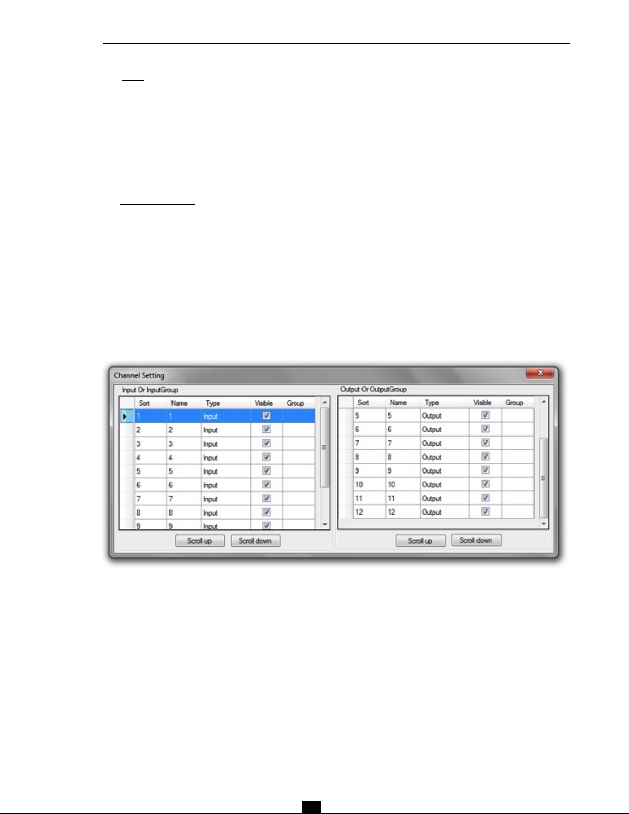
b - Channel Setting
Conduct sorting, grouping and hiding operations to the input and output channels.
• Sort: shows the position of channels on the screen. To change a position, select a channel and use the
commands Scroll up and Scroll down.
• Name: Select the channel, click in the cell in the column Name and change the name.
• Type: Displays channel attributes, cannot be modified..
• Visible: viewing or hiding a channel on the screen.
• Group: displays information for the channels that are grouped.
Menu Bar
5
7
1 – File
• New: Create a new editing file. Original parameters are configured at the factory.
• Open: Load a saved scene.
• Save: Save the current configuration to the local disk.
• Exit: Exit from the software.
2 - Local Settings
a - RC panel Configuration
Refer to the operating instructions specific to the programming of the control panels by opening the menu and
by clicking on the icon « ? » Then select the language English or French in the dialog box.
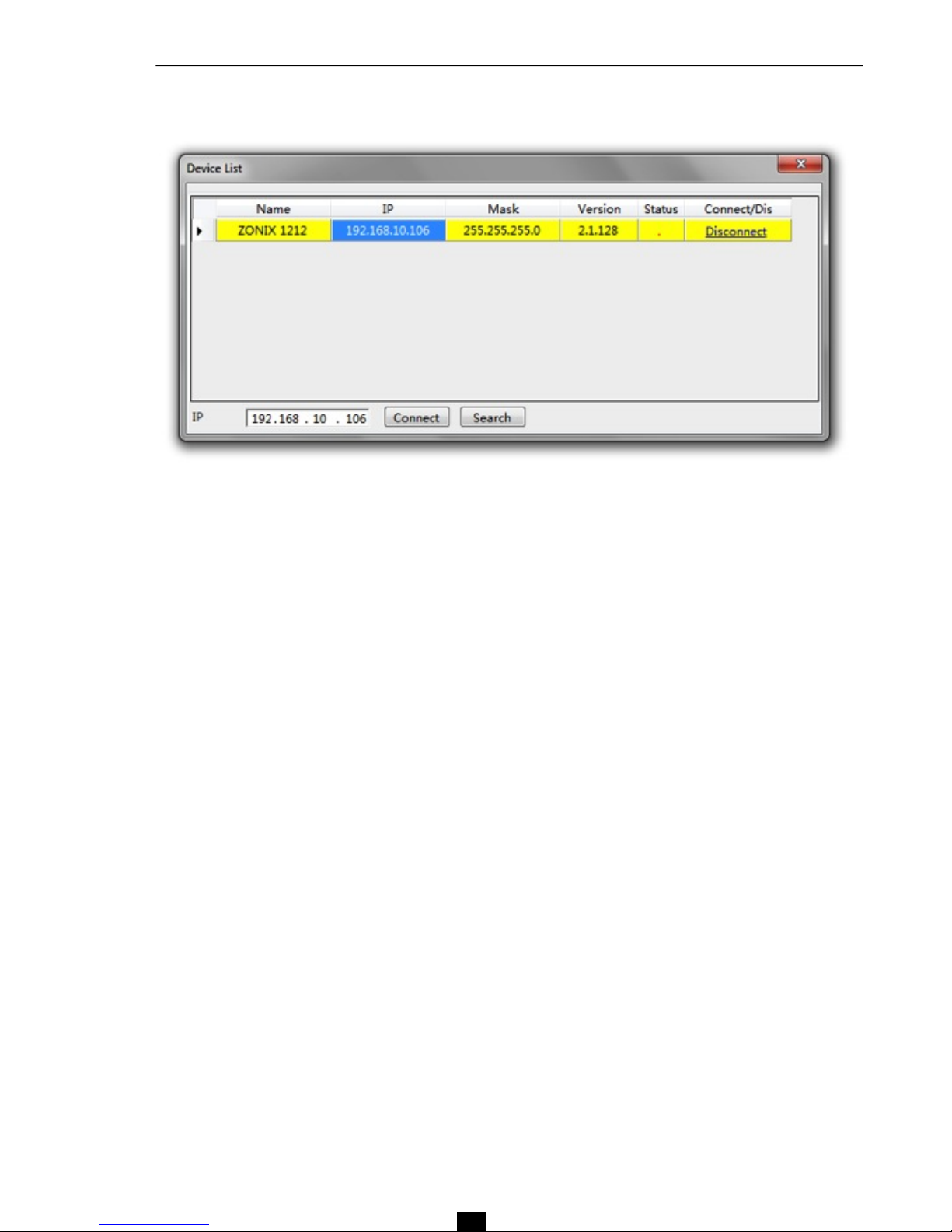
c - Device List
• Click Search to check the devices in the current LAN. The search result is shown above. If the IP address is
known, input it. Then click Connect.
• The sign " ! " in the column Status indicates that there is a problem with the network connection. Then
check the IP addresses and repeat the operation.
• If Connect is displayed in the column Connect / Dis, the device is not connected (off line). If it displays
"Disconnect" the device is connected (on line).
• The user information are required when connecting the device (see page 10).
d - Connect
Connect the latest connected device.
e - Disconnect
Disconnect the current connected device.
Menu Bar
5
8

Menu Bar
5
9
f - Center Control Command
The Center Control Command displays commands of the ZONIX 1212. The commands code can be used by an
external device to control the ZONIX 1212.
Using the Copy function, the codes can be pasted into a control program directly, saving time and avoiding
transcription errors.
• Set - Query: select the display between command and query.
• Reply / NoReply : select command Reply or not.
• Top: Foreground display of the module on the screen.
• Command: command code display.
• Copy: copy the command code to be pasted in an external control device program.
• Processor type: selection of the processing modules.
• Processor Index: to index the processor module.
• Item: parameter selection in the processing module.
• V0, V1, V2, V3: parameters value.
• Begin Channel, End Channel: audio channels concerned. If the command acts simultaneously on
channels 1 to 4, enter 1 to “Begin Channel” and 4 to “End Channel”.
• Check Sum: data check sum calculation.
To close down , click on Center Control Command again in the Local Seting menu.
10
Menu Bar
5
3 – Device Settings
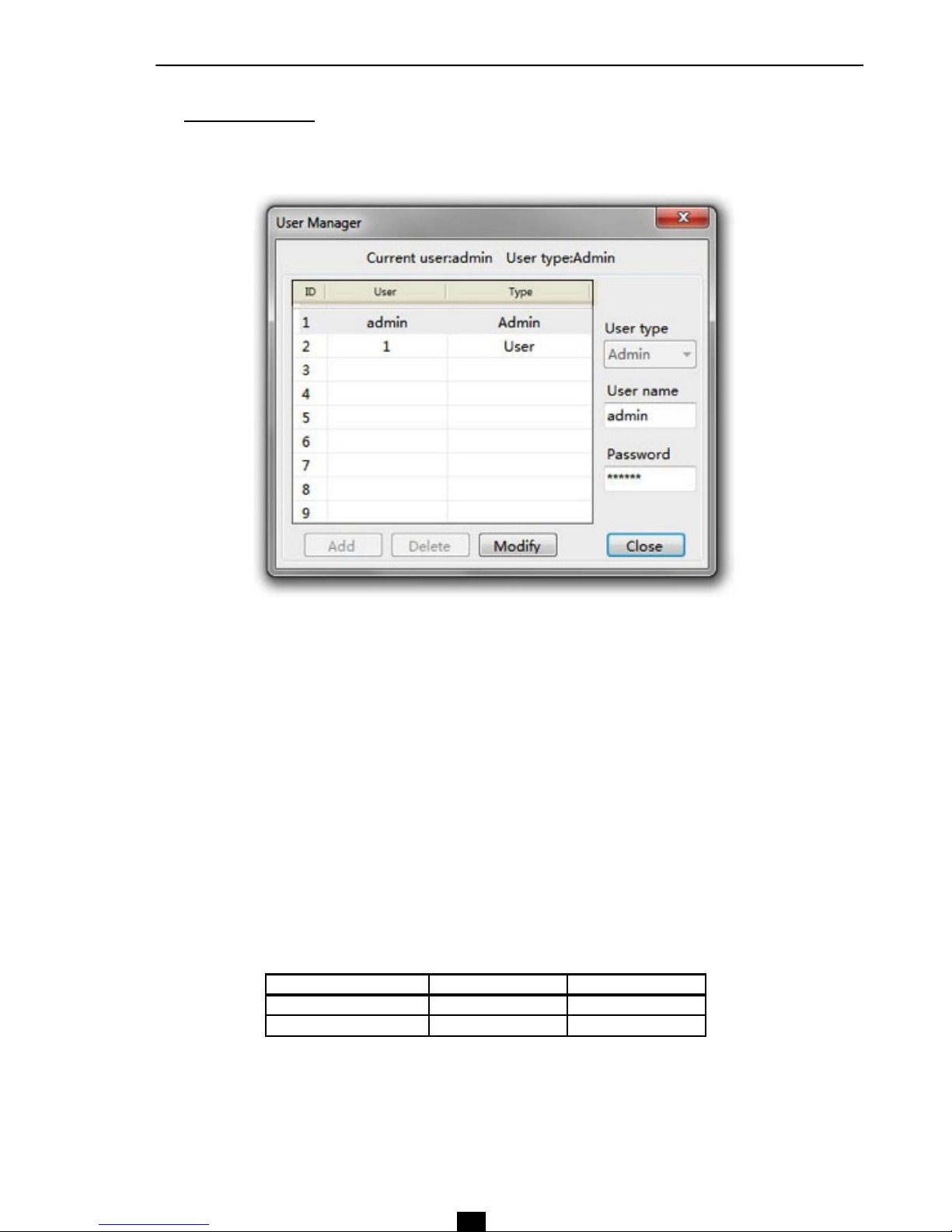
a - User Manager
The system administrator can add, delete and modify his own data as well as those of general users; the
general users, on the other hand, can only operate their personal data. The procedures are as follows:
• Modify User Information: first select a user from the list. Change the data displayed in the fields User
name and Password and then click Modify.
• Delete one user (by the system administrator only) : Select the user and click on "Delete".
• Add a user (by the system administrator only): Select a blank row and insert information from a new user
through the fields User name and Password and then click Add.
List of default users
Type User Name Password
Administrator admin 123456
General user 1 1
11!
Menu Bar
5
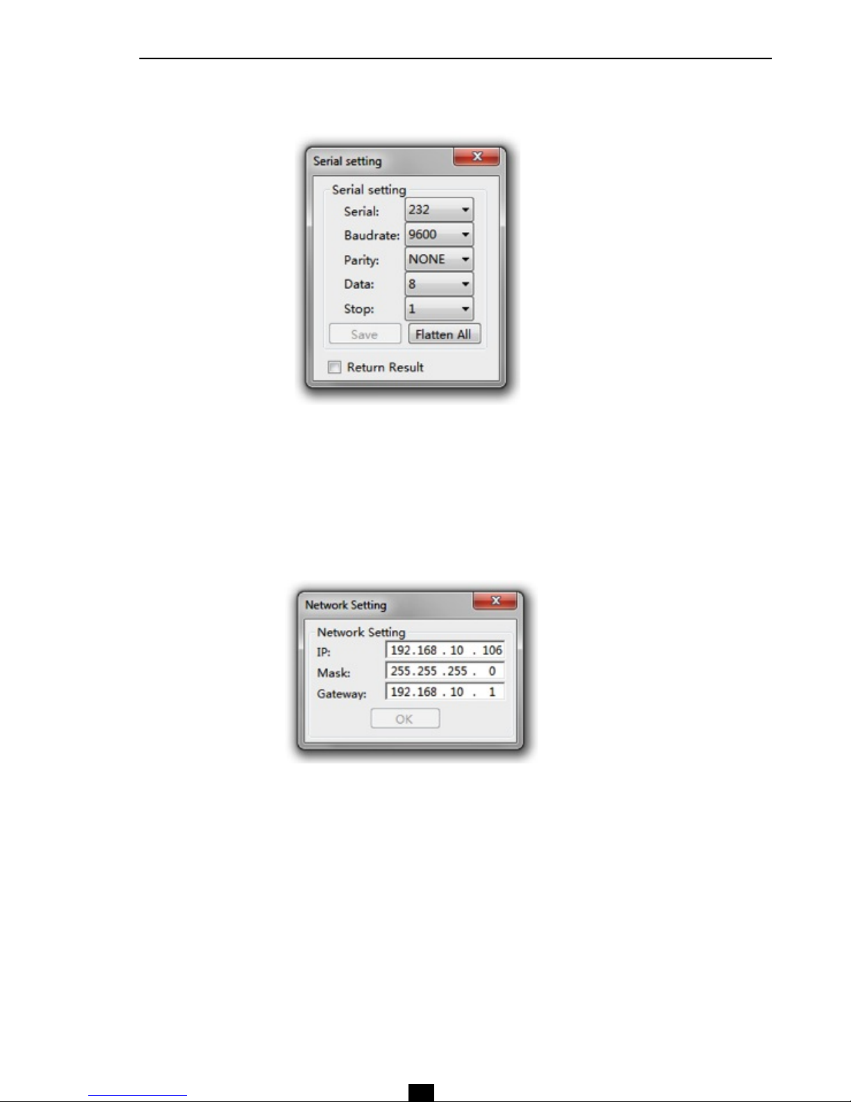
b - Serial Settings
To view and modify the settings of the serial ports.
c - Network Settings
To view and modify the components of network setting.

12!
Menu Bar
5
d - Scene Manager
There are 8 configuration memories called Scene. These can be edited and saved very simply.
• Rename scene: gives or changes a name. Select the line you wish to edit and then click Rename scene,
enter the new name in the window and confirm.
• Save to device: saves the current scene in the device’s memory.
• Reset: resets the configuration being edited.
• Reset All: resets all scenes.
• Load scene: makes active a scene saved in the device.
• Upload to device: loads a scene stored in the PC to the device's memory. Once loaded, click on Load
scene to activate the scene in the device.
• Download to local: saves the current edited scene in the PC's memory.
• Set Default Start Scene : sets a default scene when the device starts.
• Cancel the default boot : cancels the previous operation.

13!
Menu Bar
5
e - Voice Tracking
The Voice Tracking function automatically controls the position of a video camera or sends an external control
signal based on the detection of a signal picked up by a microphone.
Track setting
• Enable tracking: activation of the Camera (Camera Track) and command (Custom command) data. The
Camera information can directly control the position and the settings of a video camera. The information
command, available on the communication ports, are used to drive other external equipment.
• Tracking threshold: Tracking settings are activated only when the threshold of detected audio level
exceeds the input value.
• Default mic : selection of reference microphone defining the default settings for the camera and data
commands. The default settings are activated whenever there is no signal recognized on the inputs. The
microphone numbers with the # sign are virtual values to be used when all the others are already busy.
• Delay time (s): to start the activation of the tracking. Parasitic noise into a microphone (a person who
coughs for instance) should not trigger a camera movement or another event.

14!
Menu Bar
5
• Switch default mic times (s): duration before the camera is supposed to return to the default position.
Equivalent to define the duration of what are considered as silences or pauses, they do not justify camera
movements.
• Gap time (ms): time interval between two command data, the commands for the camera or the serial port
are sent redundantly.
Camera setting
• Serial: selection of communication port RS232 or RS485 to control the camera.
• Camera addr. : addressing the camera from 1 to 32.
• Protocol: selection of the control protocol of the camera, PELCO_D, PELCO_P, VISCA.
• Speed: speed of movement of the camera.
• Up, Down, Left, Right, Zoom in, Zoom out, Near, Far, Big, Small: camera control commands.
• Preset: preset from 1 to 32 to store the camera settings.
• Call : call a Preset.
• Save: save the current Preset.
• Clear : clear the current Preset.
Set Mic Tracking
• Mic NO.: Number of the microphone. Values followed by the # sign correspond to virtual microphones.
• Priority : values from 1 to 7. The highest priority is 1. In the event of a detection by several microphones at
the same time, positioning the camera will be carried out on the basis of the degree of priority.
Mic setting
• Enable the mic setting: selects the position of the camera by the microphone detection.
• Serial: selection of the communication port of the camera.
• Camera addr: selection of the camera 1 to 32.
• Protocol: choice of camera control protocol.
• Preset: choice of a Preset.
Custom command
• Enable custom command: Enables sending command data.
• Serial: selection of the communication port for the external command.
• Window box: command codes to be sent to the communication port.
• Send : sends command codes.
• Save: saves settings for the selected microphone.

15!
Menu Bar
5
f - GPIO setting
The rear panel of the audio matrix has a DB25 connector for the connection of the GPIO.
Channel outputs 1 to 8 correspond to the upper pins of the DB25 connector (original state is "high" logic level).
Channels 5 to 8 are electrically OC (open collector) to be used with a reference voltage of + 12 V and max of
60 mA.
Channels outputs 1 to 4 are common level output with reference voltage of 3.3 V. The maximum output current is
0.4 mA when it outputs "high“ level and -30 mA when it outputs “low" level.
Channel inputs 1 to 8 correspond to the lower pins of the DB25 connector. The inputs are isolated by put-up
resistors and support input levels of 3.3 V to 12 V.
!
Select a GPIO number then use the various settings available.
The buttons colored in orange indicate active GPIO, in grey inactive GPIO.
The example above shows the active R.O 1 output, the other GPIO being inactive.
GPIO Enabled : to make the selected channel active or inactive. The user can determine the electrical level and
input/output parameters, then validate them by clicking on Save or Apply. These changes are effective only in
"On“ position.
Before moving to an another GPIO you must click Apply to validate the parameter editing and their storage.
The Save button saves all changes and closes the edit window.

GPIO wiring
#
#
#
#
#
#
#
#
#
#
#
#
#
#
Outputs (R.O 1 ~ 4 and R.O 5 ~ 8)
When a parameter of the device varies (for example, a channel is forced to MUTE), some GPIO output level
changes accordingly and command an external circuit.
Outputs R.O 5 ~ 8 are electrically OC (Open Collector), and must use a reference voltage of 12 V, which is
accessible to pin 13 and 25 of the DB25 connector.
With a switchable power level of 0 to 12V and a high current, the output are generally used for switching relay,
buzzer and other high power consumption equipment.
Outputs R.O 1 ~ 4 are outputs with ordinary power level, current max being 0.4 mA when the level is "high" and
-30 mA when the level is "low" .
Inputs (R.I 1 ~ 8):
An external circuit changes power state and shall communicate it to a GPIO pin that controls the change of a
parameter in the device.
Wiring output R.O 5 ~ 8
The electrical characteristic OC (Opened Collector) of output R.O 5 ~ 8 requires that a resistance of 10 kΩ be
inserted between pins 13 and R.O 5 ~ 8 to obtain the required 12 V reference.!!
!
As shown in the diagram above, pin 13 is constantly at + 12 V; PIN 11 (R.O 8) switches from 0 to 12 V
depending on changes in the device.
#
16!
Menu Bar
5

17!
Menu Bar
5
Examples
1 - Settings with Scene Display:
Go to the GPIO Setting menu, click R.O 8, then GPIO Enabled On, then Apply. Change settings as shown in
the following example, and click Apply again.
!
In this example, if Scene 8 is loaded using the Stage manager menu, pin 11 (R.O 8) will be in the electrical
"low" level, and will remain in this state until another Scene is loaded. At that time pin 11 (R.O 8) will switch to
"high" level. !
!
!
!
!
!
!
!
!
!
!
!
!
!
!
!
!
Important, the settings will be effective only after validation by clicking Apply.
2 - Settings with Level Display:
!
!
!
!
!
!
!
!
!
!
!
!
!
!
!
!
!
!
In this example, if the channel 1 input level remains below -28 dB, R.O 8 remains "low". If the level of channel 1
passes over -28 dB, R.O 8 level becomes "high".

18!
Menu Bar
5
3 - Settings with Mute Display:
!
!
!
!
!
!
!
!
!
!
!
!
!
!
!
!
!
When channel 3 output is in Mute position, R.O 8 is "high". If Mute is removed, R.O 8 transitions to "low“.
4 - Settings with SysMute Display:
When all the output channels are in Mute position, RO 8 is "low". If Mute is removed, RO 8 transitions to "high".
!

19!
Menu Bar
5
Wiring output R.O 1 ~ 4
Unlike outputs R.O 5 ~ 8, outputs R.O 1 ~ 4 are 5 V outputs issuing a 0.4 mA Max current in "high" level and
-30 mA in "low" level.
!
Example
!
!
!
!
!
!
!
!
!
!
!
!
!
!
!
When the Scene 6 is loaded, pin 3 of the connector (R.O 1) issue a "low" level (< 0.7 V); when another Scene
is loaded pin 3 issue a "high" level (> 4 V).
Wiring Input R.I 1~8
In the above diagram the pin 16 switching state (R.I 1) is "high" (open).

20!
Menu Bar
5
The settings for a Scene load are as follows: the device will automatically load the Scene 4 when the pin level
corresponding to R.I 1 will switch from "high" to "low" (Falling Edge).
!
!
!
!
!
!
!
!
!
!
!
!
!
!
If the switching status changes from "open" to "closed", pin 16 electrical level will pass from "high" to "low",
forming an electrical Falling edge that will command the device to load Scene 4.
If the switching status changes from "closed" to "open", pin 16 electrical level will pass from "low" to "high",
forming an electrical Rising edge that will command the device not to change the configuration.
. 3 – Help
a - Content
Choice of language of the instruction manual
b - About

21!
Inputs
6
!
!
!
!
!
!
!
!
!
!
!
!
!
!
Depending on the size of the screen, the graphic interface cannot display all the channels, then use the arrows
on the left to move the page to one side or the other and thus visualize the missing channels. Click on the
channel for modifications, its settings will appear in the upper windows.
A channel setting configuration include the following information:
1. Number or name of the channel. The indication may be modified and may contain up to 15 alphanumeric
characters, including 6 visible in the window.
2. Led icon indicating if the input channel is controlled or receives the signal via an external remote control
panel. The light has three states: on, flash or off:
3. Pre : Indicates whether the displayed input level is Pre fader (blue light) or post-fader (light off).
4. Adjustment and visualization of the input by the position of the fader gain.
5. Value of the input gain.
Light state Use of the external remote
control panel authorized
Presence signal on the
remote panel
On Yes Yes
Off Yes / No No
Flash No Yes
5
1 2 3 4

22!
Inputs
6
1 - Creating Groups of Inputs
Inputs can be grouped for common modifications, so when one changes the gain of a group, all channels in the
group will be affected.
To create a group use the right click of the mouse, click on a channel, choose Add To Group or Add To DCA,
then select the number of a group of 1 to 4. A new fader appears with the reference of the created group. The
name of this group can be changed if necessary.
Groups called Group directly adjust the gain value, those called DCA adjust the gain percentage.
Just proceed identically for each channel you want to integrate into a group. The same channel can belong to
multiple groups Group or DCA.
To remove a channel from a group, use the same procedure but use the right click of the mouse with the Delete
Group From or Delete DCA From options.
To remove a group, right-click the Group and select Delete.
The indication of the grouped channels is marked by red dots on the faders.
2 - Manage the Position of the Faders
!
!
!
When a fader group is moved, the associated channels materialized by an orange color move their fader as
well.
If you want to move a fader group next to its associated channels or have it near other fader groups, click in the
Local Setting menu bar then select Channel Setting, then click the fader to move and use the Scroll up and
Scroll down buttons (see page 8).

3 – Input Parameters
Each channel has its own processing modules. Therefore, individual setting becomes necessary. The Copy /
Paste (see page 6) allows to simplify programming by copying settings from one module to the other, without
having to enter all data on an individual basis.
• Sensitivity : the sensitivity of the Microphone and line input can be adjusted from 0 dBu to -54 dBu by
clicking on the proposed values.
• Panel call: sets the signal from an external remote control panel to the input channel.
• Mute: cuts the input signal and lights red indicator M. On the front panel of the device the Led
corresponding to the channel unit lights up red.
• Test Tone: activates a pink noise, white noise or variable frequency sinusoidal signal. The level can be
adjusted from 0 dB to -60 dB.
• Phantom: activates a Phantom power for electret microphones. Caution, do not use this option for dynamic
microphones or line connections, this may damage the equipment.
!
!
!
23!
Inputs
6

24!
Inputs
6
4 - Expander / Gate
The capabilities of the Expander are to add Dynamics to a signal. When the signal is below a certain threshold
the Expander boosts the input signal with a determined ratio. When the signal is beyond the threshold, the
output signal remains identical to the input signal. By adjusting the value of the ratio to its maximum, the
Expander is transformed into a Noise Gate.
• Bypass: the signal is not processed and skips to the next processing module.
• Ratio: gain ratio between the input signal and the amplified signal.
• Attack time: reaction time of the Expander when the signal is below the specified threshold.
• Release time: reaction time of the Expander when the signal passes beyond the specified threshold.
• Flatten All: all parameters are reset to the factory settings.
!
!
!

25!
Inputs
6
5 – Parametric EQ
An equalizer is used to compensate or alter the spectral characteristics of the signal in order to obtain the
flattest possible frequency response. The module here is a parametric 5 bands EQ.
• Freq: central frequency of the filter between 20 Hz and 20,000 Hz.
• Gain: gain or attenuation wedged on the center frequency.
• Octaves: selectivity of the filter (Q). Greater is the value, larger is the part treated of the spectrum.
• Flatten All: all parameters are reset to the factory settings.
• Bypass All: the signal is not processed and skips to the next processing module.
• Bypass 1~5: temporarily cancels the individual processing of filters 1 ~ 5 without having to use “Bypass All”.
!
!
!

26!
Inputs
6
6 - Compressor
A compressor can limit the dynamics of a signal beyond a certain level. When the signal exceeds the Threshold
it is compressed in a ratio greater than 1. Below the Threshold, input and output signals remain the same. By
adjusting the value of the ratio to its maximum value, the compressor is transformed into a limiter.
Threshold: threshold from which the signal is compressed.
Ratio: ratio between the input signal and the compressed signal.
Attack time: reaction time of the compressor when the signal is beyond the specified threshold.
Release time: reaction time of the Compressor when the signal is below the specified threshold.
Bypass: the signal is not processed and skips to the next processing module.
Flatten All: all parameters are reset to the factory settings.
Output: output level of the compression module.
!
!
!

27!
Inputs
6
7 – Automatic Gain Control (AGC)
The AGC module or "Automatic Gain Control" is the combination of an Expander and Compressor and is used
to compensate for variations in levels of the voice picked up by a microphone. If the level is below a certain
threshold, the signal is amplified in a defined ratio until you reach a peak level. Beyond this level the signal level
is compressed in order to remain within a range of stable gain.
Input: input level of AGC.
Output: output level of AGC.
Threshold: threshold of the Expander action.
Target Level: Max level.
Ratio : ratio of the Compressor
Attack time: reaction time of the Expander.
Release time: reaction time of the Compressor.
Flatten All: all parameters are reset to the factory settings.
Bypass: the signal is not processed and skips to the next processing module.
!

28!
Inputs
6
8 - Scene Manager and GPIO
The stage Manager section includes the options Select Scene, Upload, Save and Load. It is a simplified
version of the Scene Manager menu in Device Setting (see page 12).
Save saves the settings in the device,
Upload load settings from the PC's hard disk in the device by overwriting the previous one.
Load makes active the scene saved in the device..
The GPIO section shows the status of the input/output interfaces. 16 indicators provide information about the
level "high" or "low" of the DB29 connector pins. The indicators are red in the case of a "high", yellow in the
case of "low" and green if they are not enabled.
!
!
!

29!
Inputs
6
9 - Ducker
The principle of the Ducker is to attenuate one or more channels by the presence of a signal on other inputs.
The main applications are automatic speech in conference and priority messages.
Paging Input: choice of the priority channel.
Background Input!: selection of channels being affected by the attenuation.
Threshold: threshold of attenuation.
Depth: depth of attenuation.
Attack: time of transition between the normal and the attenuated level.
Hold: holding time of attenuation after disappearance of the priority signal.
Release: transition time between the attenuated level and return to the normal level.
Bypass: the signal is not processed and skips to the next processing module.
Flatten All: all parameters are reset to the factory settings.
Reduction: dynamic display of attenuation.

30!
Inputs
6
10 – SPL (Ambient Noise Controller )
SPL means Sound Pressure Level. This terminology is associated here with a module of automatic correction of
the output level in relation with the ambient noise. This feature is called Ambient Noise Controller (ANC) and is
very useful in places where noise is brought to vary frequently as in a shopping mall based on hours of
attendance or sports venue depending on the type of event and the number of spectators. Overall, the ANC
increases the output signal when ambient noise increases and vice versa.
The treatment can be applied or not depending on the broadcast signal levels. If the level is sufficiently high
compared to the ambient noise there is not need to process. If the signal is too weak to be heard clearly it
needs to be amplified. It is often the case of an intermittent signal of vocal announcement where the gain
variation, if applied, must be immediate. For a continuous signal, like background music, the gain variation can
be activated
after certain intervals of time.
1. Sense input: selecting the channel receiving the analysis microphone.
2. Program input: selection of channels treated by the ANC with their relative level.
3. SPL Control:
• Max Gain (dB): upper limit of the output level when the ambient noise is very loud.
• Min Gain (dB): lower limit of the output level when the ambient noise is very quiet.
• Gain-Sense Ratio: ratio between the increase in ambient noise and the increase in the level of channels to
treat. A ratio of 1.00 means that a variation of 1 dB of ambient noise will cause a variation of 1 dB of the
output level. For a ratio greater than 1.00, the gain variation will be most important and for a lower ratio, gain
variation will be lower.
• Speed (sec): speed of the gain variation.
• Gap Threshold (dB): threshold from which it determines whether the signal is intermittent or not (messages
or continuous background music, etc.).
Once the ambient noise threshold is set (see next page), open the channel with the signal to process and
adjust the slider so that the Led Gap Flag is illuminated for an intermittent signal or turned off for a
continuous signal.

31!
Inputs
6
• Gap Time (ms): any intermittent signal whose time is less than the value displayed is considered as a
spurious signal and is not processed.
• Gap Interval (min): time interval to activate the ANC for a non-intermittent signal (continuous background
music).
• Gain (dB) : display of the dynamic value of the applied gain.
• Gain High / Low (dB) : display of minimum and maximum of gain values.
• Gap Flag: light detection setting the type of signal (intermittent or continuous)
• Flatten: parameters of the windows are reset to the factory settings.
• Force Gap: force the activation of the ANC for a non-intermittent signal (Equivalent to Gap Interval but
immediately)
• Calibrate: force the value of the Threshold of ambient noise to the value indicated on the Sense bargraph.
Attention, the captured value is not displayed on the indicator and the Threshold slider.
• Sense: display of the signal picked up by the measurement microphone. Allows to adjust the level of
ambient noise.
• Threshold (dB) : manual adjustment of the threshold of the ambient noise.
• Bypass: the signal is not processed and skips to the next processing module.
• Flatten All: all parameters are reset to the factory settings.
Outputs
7
Depending on the width of the screen the number of visible outputs may change. Use the arrow keys to move if
necessary. As for inputs, the outputs can be grouped in GROUP mode or DCA mode (see page 22).
The display shows:
• the name or number of the channel, this info may be amended,
• PRE/POST indicates whether the value of the output level is pre or post fader,
• the level display and the fader,
• the output gain.

32!
Outputs
7
1 - Source
This module routes the inputs, Ducker and SPL modules to the outputs.
First select the output channel, and then click on the input channels as well as the Ducker or SPL modules that
you want to assign to this output. The inputs can be routed on several different outputs.
2 - Speaker Manager
This module processes the signal EQ to drive the amplification system assigned to each output. It combines a 8
bands parametric equalizer where you can adjust the center frequency, gain and selectivity, plus a high-pass
filter and low-pass filter.

33!
Outputs
7
a) Parametric filters
The data can be entered in numerical value in windows F, G and Q, or via the computer mouse directly on the
curve.
• Input : display of the input level in the processing module.
• Bypass1~8 : individual bypass of filter 1~8
• F, G, Q : adjustment of the center frequency, gain and selectivity.
• EQ Bypass!: bypass of all filters simultaneously.
b) Crossover
!
• Low Bypass, High Bypass : LPF and HPF filters bypass.
• F, G : adjustment of the cut-off frequency and gain.
• Butterworth, Bessel, Linkwitz-Riley : filter type selection.
• 6 ~ 48 : selection of the filter slope (dB).
•
c) Delay
• Delay Bypass : delay bypass and delay adjustment in milliseconds (0 ~ 2000) or meters (0 ~ 680)
• Invert : phase inversion.
• Main Bypass : bypass of the whole Speaker Manager module.
• Flatten All : all parameters are reset to the factory settings.
• Output : adjustment and display of the output level for the whole module.
• 3 - Limiter
The Limiter protects against an excessive output signal sent to external devices by limiting the gain once it
exceeds a certain threshold.

34!
Sorties
7
• G.R : displays the limitation value.
• Output : displays the output level of the module.
• Threshold (dB) : limitation threshold setting.
• Release (ms) : reaction time of the limiter.
• Flatten All : all parameters are reset to the factory settings.
• Bypass : limiter bypass.
4 - Output setting
• Sensitivity: selects output sensitivity at 0 dBu, -6 dBu, or -12 dBu.
• Mute: Output channel mute (similar to the M button above each channel faders)

35!
Technical Features
8
DSP Texas Instruments L138
A/D-D/A Converter 24 bits / 48 kHz, sampling up to 96 kHz
Dynamic Range
Converter:114 dB
Input to Output: 110 dB
Inputs
• x 12
• Balanced Mic / Line, Phoenix connector
• Impedance: 2 kΩ!
• Gain max: 54 dB
• Phantom Power 48 V
Outputs
• x 12
• Balanced, Phoenix connector
• Impedance: 100 Ω!
• Max level: 20 dBu
Channel Crosstalk 100 dB @ 1 kHz, +20 dBu
Frequency Response 20 Hz - 20 kHz (+/- 0,5 dB)
Harmonic Distortion (THD+D) ≤ 0,005 % @ 1 kHz, +4 dBu
Equivalent Input Noise (EIN) ≤ -128 dB (20 Hz – 20 kHz, A weighted)
Control Interface
• RS 232 bidirectional (AMX, Crestron compatible)
• RS 485 (PELCO D, PELCO P, VISCA compatible)
GPIO
• 8 Inputs
• 8 Outputs
Network M-LAN multi-purpose data transmission and control port
Remote Control Panels
• Key, Knob, Call, Mixer Type Wall
• TCP/IP , POE adaptive control interface
Software Windows XP, Windows Vista, Windows 7, Windows 8 compatible
Operating Temperature 0 – 40 °C
Power Supply ~ 110-220 V, 50/60 Hz
Dimensions (L x D x H) 483 x 265 x 44 mm
Net Weight 2.8 kg

35!
Warranty
9
22, rue Édouard Buffard, Z.A.C. de la Charbonnière, Montévrain - 77771 Marne-la-Vallée Cedex 4 - France
Tél : + 33 (0)1 60 54 32 00 - Fax : + 33 (0) 1 60 54 31 90 - www.audiopole.fr - www.audiopole-pa.com
Conditions
1. The unit has been installed and implemented by observing the safety instructions in this operating manual.
2. The device was not diverted from its destination, either voluntary or accidental, and suffered no
deterioration or modification other than those described here or explicitly authorized by AUDIOPOLE.
3. All modifications or repairs have been carried out by an authorized service station.
4. The defective product must be returned with the dealer who made the sale or to an authorized service
station with proof of purchase.
5. The device was properly packaged to avoid damage in transport.
This appliance is warranted parts and labor against any manufacturing defects for a period of two years from
the date of purchase by the first user.
 Loading...