

Audiopipe APMR-1504 Owners Manual
- 1 -

English
The Audiopipe APMR-1504 is a full-featured four-channel marine amplifier incorporating
the following features:
Specially coated circuit boards, that resist mold, mildew and moisture damage.
•
Pulse-Width Modulated (PWM) MOSFET power supply for maximum performance with
•
minimal distortion.
Remote turn-on with "soft start" muting to prevent turn-on "thump".
•
Advanced circuitry design featuring bridgeable and mixed mode operation for use in
•
various system configurations including 4, 3, or 2 channel systems.
Variable high-pass/low-pass electronic crossover with a 12dB per octave slope (adjustable
•
range: 55Hz to 5.5kHz).
Variable bass boost circuit to reinforce low frequency signals that may be lost due to
•
subwoofer enclosure design.
Adjustable input level controls with ground loop isolation to minimize noise and distortion.
•
2 Ohm stereo stable, 4 Ohm mono stable.
•
Platinum-plated power, speaker, and RCA connectors.
•
Speaker level input.
•
Low profile construction with aluminum heat sink for efficient heat dissipation.
•
This manual describes the basic requirements to install the Audiopie APMR-1504 marine
amplifier. The installation of this marine amplifier can be quite complex to install, if you
do not possess the necessary knowledge and tools to perform this installation, please
contact your local Audiopipe dealer.
Description .....................................................................................................................
Input Connections and Audio Controls ...........................................................................
Connections for Power and Speakers ............................................................................
Installation ......................................................................................................................
Mounting Precautions ....................................................................................................
Wiring Precautions .........................................................................................................
Wiring and Applications ..................................................................................................
Setting the Gain ..............................................................................................................
Setting the Crossover .....................................................................................................
Setting the Bass Boost ...................................................................................................
Final System Check .......................................................................................................
Troubleshooting .............................................................................................................
Product Specifications .............................................................................................
1
1
3
5
5
5
6
11
11
11
11
12
12
- 1 -
English
The APMR-1504 uses an unregulated MOSFET power supply for superior sound and
output wattage. In addition, a torpid-coil is used to transfer power with minimal performance
loss due to heat. To avoid unwanted noise, a double-sided conformal printed circuit board
with strategically placed components keeps AM RFI subdued.
All of the connections and controls for the APMR-1504 are conveniently located at the
ends of the marine amplifier and labeled appropriately. To ensure the best possible electrical
connections, the power, speaker, and RCA inputs are platinum-plated. An additional benefit
of this marine amplifier is the ability to create a 2, 3, or 4 channel amplified system with
a flip of a switch (see Application section). In the event of component failure or a short
circuit, the APMR-1504 incorporates safe guards and an outboard ATC fuse to prevent
damage to the marine amplifier.
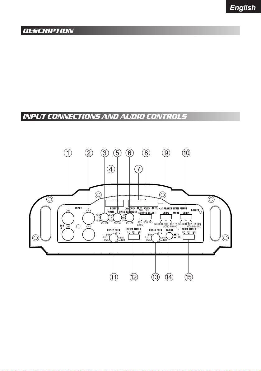
The front panel of the APMR-1504 contains both connections for RCA and speaker level
inputs, along with the audio controls as shown below.
Figure 1
1. CH1 / CH2 RCA Level Input
2. CH3 / CH4 RCA Level Input
3. CH1 / CH2 Gain Control
4. Remote
5. CH3 / CH4 Gain Control
6. CH1 / CH2 Bass Extender
7. Speaker Level Input
8. Source Select
9. CH1 / CH2 Mode Switch
10. CH3 / CH4 Mode Switch
11. CH1 / CH2 Frequency Control
12. CH1 / CH2 Crossover Mode Switch
13. CH3 / CH4 Frequency Control
14. Frequency Range Multiplier
15. CH3 / CH4 Crossover Mode Switch
- 1 -

English
The Input Connections are platinum-plated RCA Jacks and are labeled as FRONT RIGHT,
FRONT LEFT, REAR RIGHT and REAR LEFT. The Gain Controls provide a wide adjustment
range to accommodate output levels from any brand of source unit.
Gain Controls
Separate Front and Rear Gain Controls allow you to set the nominal operating level of the
marine amplifier. The marine amplifier’s range, 250mV to 2.5V for RCA inputs or 500mV
to 5V for speaker level inputs, can accommodate input levels from virtually any brand of
source unit.
Bass Boost Control
The marine amplifier also features a “high-Q” (i.e. narrow frequency band) Bass Boost
circuit.
It acts much like an equalizer, with adjustable gain (from 0 to ~18dB) fixed at 45Hz. Use
this feature to tune low-frequency audio response to compensate for a less than ideal
subwoofer enclosure design. The added boost produces rich, full bass tones that are
normally difficult to reproduce in the car audio environment.
NOTE: If Bass Boost is undesired, set Bass Boost to 0dB.
High-pass/Low-pass Filter Controls
Frequency (Hz) Controls
The front crossover frequency is fully adjustable between 55Hz and 550Hz. The rear
crossover frequency is fully adjustable between 55Hz and 5500Hz (via the Rear Crossover
Frequency Multiplier) for a wider range of crossover points. Use this feature, along with
your speaker manufacturer’s recommended crossover frequencies, to quickly design a
more advanced system (see Applications on page 6). NOTE: If either of the X-Over Mode
Switches is set to OFF, varying the Freq (Hz) Control will produce no effect.
Rear X-Over Frequency Multiplier Switch
When engaged, this switch increases the crossover frequency of the rear channels by a
factor of 10. Example: If the Freq (Hz) dial is set for 240Hz, pushing in the Multiplier Switch
changes the setting to 2400Hz.
X-Over Mode Switches
These switches are equipped with 12dB per octave electronic filters for precise frequency
attenuation with minimal phase distortion. The steep crossover slopes keep midrange
tones out of the sub-woofer and thereby eliminating an unnatural “nasal” tone quality in
the audio system. Each filter is activated by sliding the X-Over Mode Switch to either LP
or HP.
Input Mode Switches
These switches allow you to set the input mode for front and rear channels. Stereo input
allows full left and right stereo operation. Right (bridged) input allows a single channel
input for bridged operation. This is especially useful in high powered systems when using
the APMR-1504 as a bridged 2-channel marine amplifier. L ~ R (sum mono) allows a
stereo input to be summed into a mono output.
Rear Channel Input Select
This switch allows you to use a 2 channel input to drive all 4 channels of this marine
amplifier.
Speaker Level Inputs
These provide connections for a high-level stereo source. In addition, these connections
are provided for installations when the source unit’s RCA outputs are unavailable.
WARNING: When using the speaker (high-level) inputs, the Black wire must be grounded
at the Radio. Failure to do this will result in noise and improper operation.
- 2 -
English
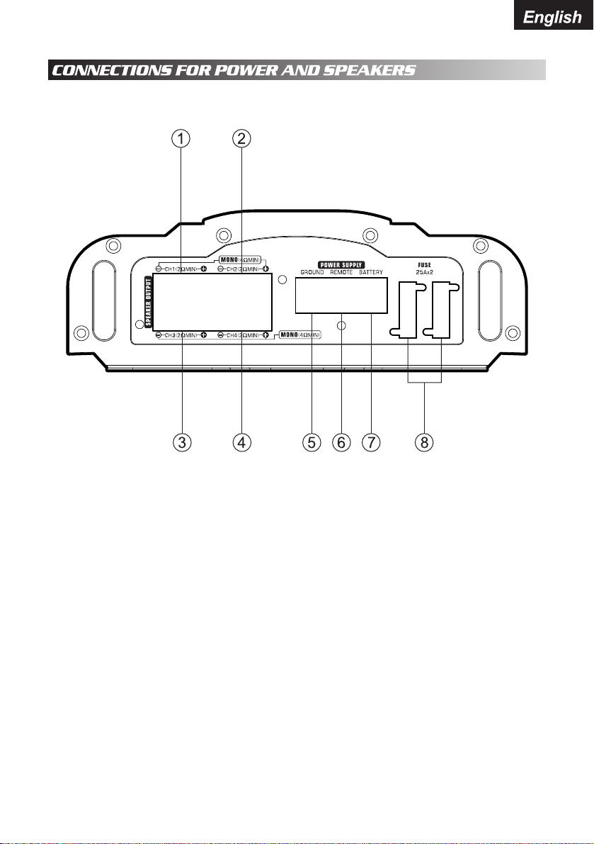
The rear panel of the APMR-1504 contains power and speaker connections as shown
below.
Figure 2
1. CH1 Speaker Output
2. CH2 Speaker Output
3. CH3 Speaker Output
4. CH4 Rear Speaker Output
5. Ground Input
6. Remote Turn-on Input
7. Battery +12v Input
8. (2)25Amp Fuses
- 3 -
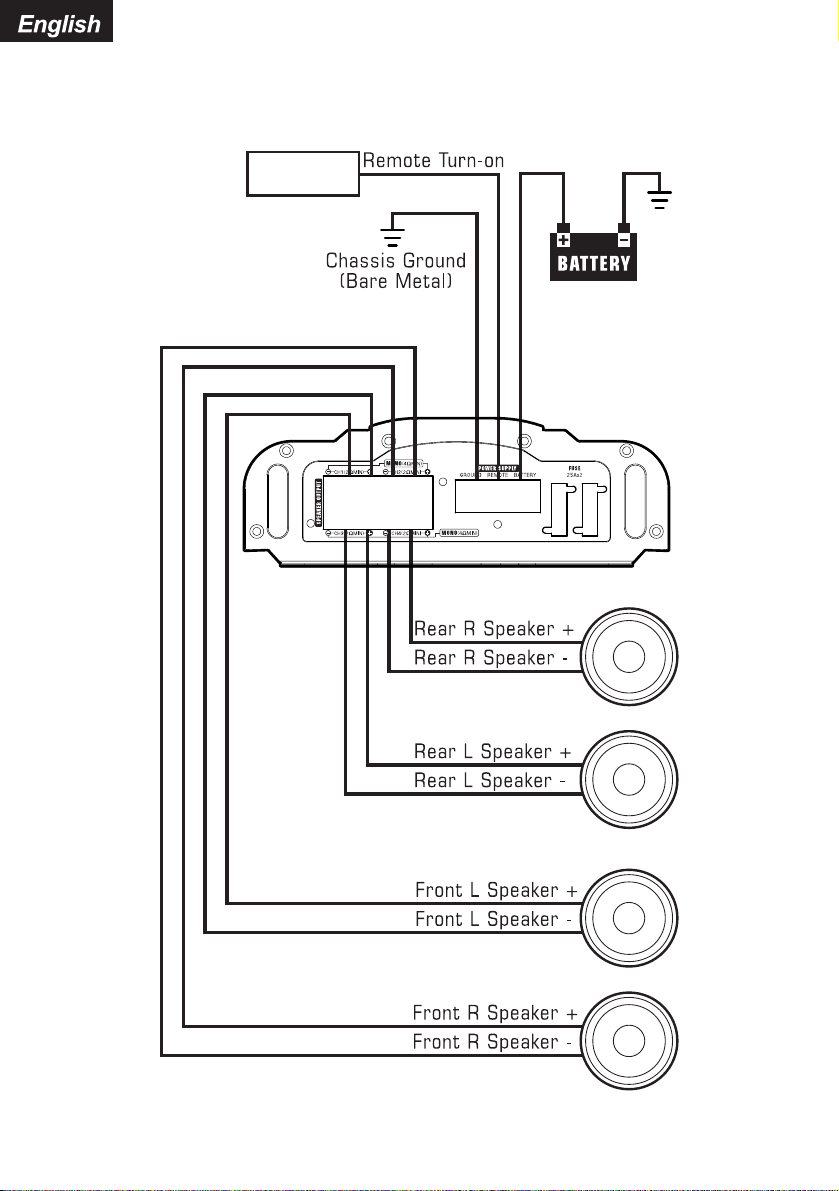
Figure 3
Connections for power and speakers
English
- 4 -

English
This section suggests Mounting and Wiring Precautions for installing the Audiopipe
APMR-1504 marine amplifier. If you do not posses the necessary tools and installation
experience, do not attempt to install this marine amplifier. Instead, contact your local
Audiopipe dealer to perform the installation.
Prior to mounting the marine amplifier, make sure it is safe to mount the marine amplifier in
that location. Failure to do so can result in serious damage to the boat. In addition, stainless
steel hardware should be used to mount the marine amplifier and additional accessories.
When possible, use a nut and bolt with a lock washer to secure the marine amplifier. Extra
care and attention is necessary in marine installations due to the uncertainty of water conditions.
Additional precautions and suggestions:
1.
For the most efficient cooling, mount the marine amplifier so cool air runs along the
length of the heat sink, rather than across them. To increase air movement and circulation,
a cooling fan can be installed.
Mount the marine amplifier on a rigid surface; avoid mounting to subwoofer enclosures
2.
or areas prone to vibration.
Prior to drilling and holes, make sure the proposed mounting holes will not cut into the
3.
fuel tank, fuel lines, electrical wiring, or through the boat.
Do not mount the marine amplifier where it is susceptible to water.
4.
Read all of the wiring precautions prior to making any connections. If you are unsure and/or
don't have the necessary installation hardware, contact your local Audiopipe dealer to
perform the installation.
Before you begin the installation, make sure the source unit Power switch is in the OFF
1.
position.
Disconnect the negative (–) lead of the battery (or batteries) before making any power
2.
connections.
When making connections, be sure that each connection is clean and secure. Insulate
3.
final connections with electrical tape or shrink tubing. Failure to do so may damage your
equipment.
A good ground is critical for the performance of the marine amplifier. A ground wire
4.
should be run directly from the battery to the marine amplifier. Use black insulated 10gauge or larger wire for the marine amplifier's ground (–) power lead.
Add an additional fuse holder and fuse at the positive (+) terminal of the battery. The
5.
fuse rating should equal the total current consumption at full output of the marine
amplifier(s). Use red insulated 10-gauge or larger wire for the marine amplifier's positive
(+) power lead. Do not install the fuse until the complete installation has been performed.
When replacing the marine amplifier's fuse, always use one having the same amperage
6.
rating. Substituting a higher rated fuse or a slow-blow type can result in serious damage
to the marine amplifier.
When creating passage holes for power cables, RCA's cords, and speaker wires, use
7.
grommets to eliminate any sharp edges created during drilling. This will protect the wire
from being nicked and causing a short circuit.
Extra cable can cause signal loss and act as an "antenna" for noise. Use only high-
8.
quality RCA cords that are no longer than necessary.
In multiple marine amplifier systems, it is recommended to use a relay on the remote
9.
turn-on lead of the radio.
- 5 -
English
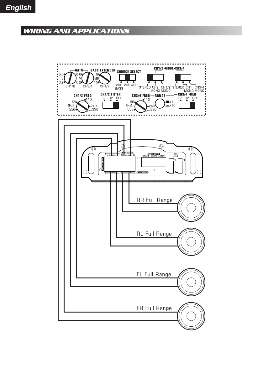
The Audiopipe APMR-1504 4-channel marine amplifier can be used in a variety of system
applications. Here are some examples to help plan your own installation.
4-Channel Full-Range Stereo System
Figure 4
In this application, the APMR-1504 is used as a 4-channel marine amplifier to drive four
full-range speakers in stereo.
- 6 -
English
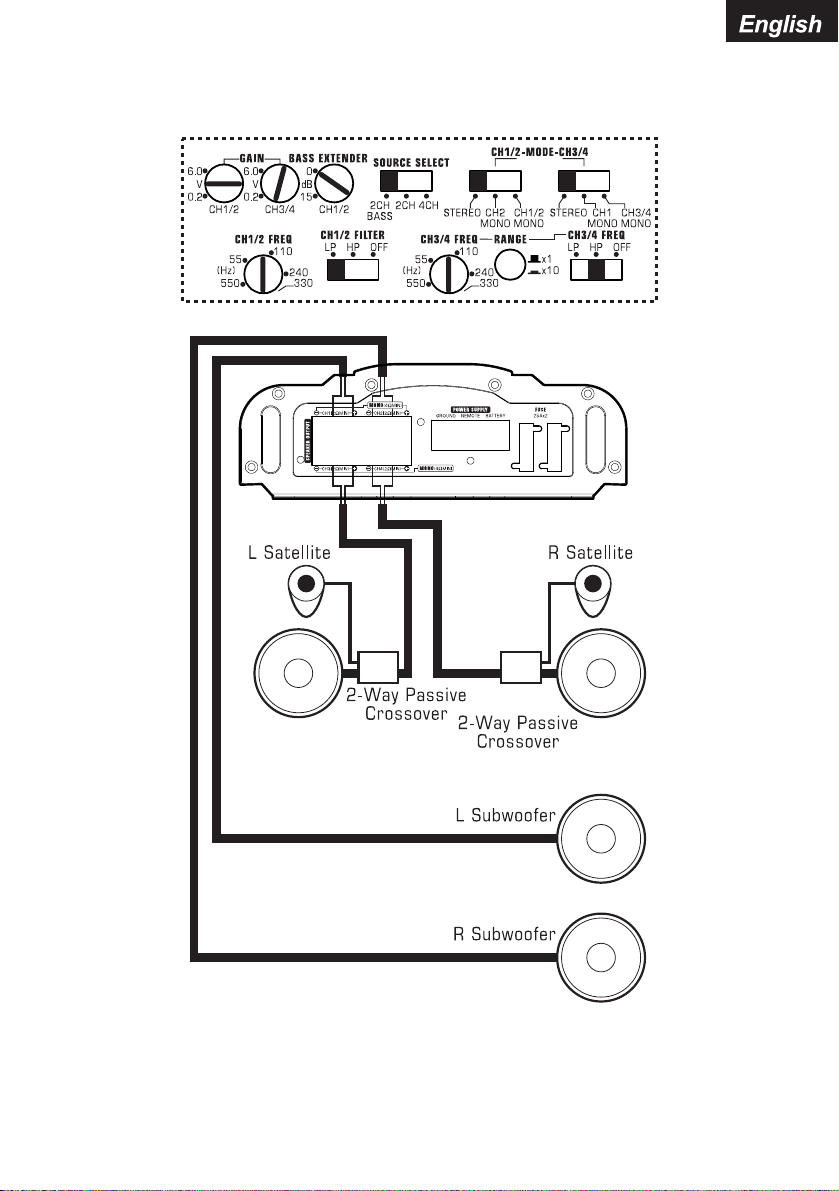
4-Channel Stereo System
2-Channel High-Pass, 2-Channel Low-Pass
Figure 5
In this 4-channel system, the APMR-1504 drives a pair of stereo satellites for the front and
a pair of subwoofers for the rear. Note the filter settings.
- 7 -
 Loading...