

USER GUIDE
9066 - December 2007 - Version 1.0
4-Channel AMPLIFIER - 4x300W at 4 Ohms
WA-4x3
ENGLISH
WA-4x3 - 4 x 300 Watts Amplifier
Page 2
1 - Please read carefully :
We strongly recommend to read carefully and understand the safety instructions before
attempting to operate this unit.
2 - Please keep this manual :
We strongly recommend to keep this manual with the unit for future reference.
3 - Operate carefully this product :
We strongly recommend to take into consideration every safety instruction.
4 - Follow the instructions:
Please carefully follow each safety instruction to avoid any physical harm or property
damage.
5 - Avoid water and wet locations :
Do not use this product in rain, or near washbasins or other wet locations.
6 - Installation :
We strongly encourage you to only use a fixation system or support recommended
by the manufacturer or supplied with this product. Carefully follow the installation
instructions and use the adequate tools.
Always ensure this unit is firmly fixed to avoid vibration and slipping while operating
as it may result in physical injury.
7 - Ceiling or wall installation :
Please contact your local dealer before attempting any ceiling or wall installation.
8 - Ventilation :
The cooling vents ensure a safe use of this product, and avoid any overheating risk.
Do not obstruct or cover these vents as it may result in overheating and potential
physical injury or product damage. This product should never been operated in a
closed non-ventilated area such as a flight case or a rack, unless cooling vents are
provided for the purpose .
9 - Heat exposure :
Sustained contact or proximity with warm surfaces may cause overheating and product
damages. Please keep this product away from any heat source such as a heaters,
amplifiers, hot plates, etc...
Sound levels
Our audio solutions deliver important sound pressure levels
(SPL) that can be harmful to human health when exposed
during long periods. Please do not stay in close proximity of
operating speakers.
1 - Safety information
Important safety information
Symbols used
Any maintenance procedure must be performed by a CONTEST
authorised technical service. Basic cleaning operations must thoroughly follow our safety instructions.
This product contains non-isolated electrical components. Do not
undertake any maintenance operation when it is switched on as
it may result in electric shock.
This unit is intended for indoor use only. Do not use it in a wet,
or extremely cold/hot locations. Failure to follow these safety instructions could result in fire, electric shock, injury, or damage to
this product or other property.
WARNING : This unit contains no user-serviceable parts. Do not open the housing or attempt
any maintenance by yourself. In the unlikely even your unit may require service, please contact your
nearest dealer.
In order to avoid any electrical malfunction, please do not use any multi-socket, power cord extension
or connecting system without making sure they are
perfectly isolated and present no defect.
10 - Electric power supply :
This product can only be operated according to a very specific voltage. These
information are specified on the label located at the rear of the product.
11 - Power cords protection:
Power-supply cords should be routed so that they are not likely to be walked on or
pinched by items placed upon or against them, paying particular attention to cords at
lugs, convenience receptacles and the point where they exit from the fixture.
12 - Cleaning precautions :
Unplug the product before attempting any cleaning operation. This product should be
cleaned only with accessories recommended by the manufacturer. Use a damp cloth
to clean the surface. Do not wash this product.
13 - Long periods of non use :
Disconnect the unit’s main power during long periods of non use.
14 - Liquids or objects penetration :
Do not let any object penetrate this product as it may result in electric shock or fire.
Never spill any liquid on this product as it may infiltrate the electronic components
and result in electric shock or fire.
15 - This product should be serviced when :
Please contact the qualified service personnel if :
- The power cord or the plug has been damaged.
- Objects have fallen or liquid has been spilled into the appliance.
- The appliance has been exposed to rain or water.
- The product does not appear to operate normally.
- The product has been damaged.
16 - Inspection/maintenance :
Please do not attempt any inspection or maintenance by yourself. Refer all servicing
to qualified personnel.
17 - Operating environment :
Ambient temperature and humidity: +5 - +35°C, relative humidity must be less than
85% (when cooling vents are not obstructed).
Do not operate this product in a non-ventilated, very humid or warm place.
Recycling your device
• As HITMUSIC is really involved in the environmental cause,
we only commercialise clean, ROHS compliant products.
• When this product reaches its end of life, take it to
a collection point designated by local authorities. The
separate collection and recycling of your product at the time
of disposal will help conserve natural resources and ensure
that it is recycled in a manner that protects human health
and the environment.
This symbol signals an important safety precaution.
The CAUTION symbol signals a risk of product deterioration.
The WARNING symbol signals a risk to the user’s physical integrity.
The product may also be damaged.
Instructions and recommendations

ENGLISH
WA-4x3 - 4 x 300 Watts Amplifier
Page 3
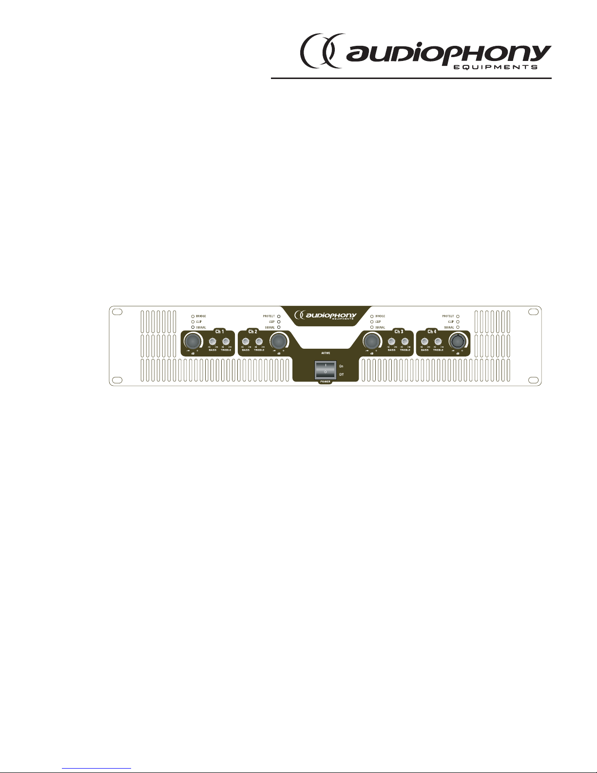
3 - Description
- Front panel
[1] - Input 1 attenuator
Each channel features its own input attenuator allowing you to limit the incoming signal level. Both
attenuators must be set to the same level and affect the same channel when the mono-bridged mode
is activated.
[2] - Inputs 1 and 2 Bridge LED
Indicate the Bridge mode is activated for inputs 1 and 2.
[3] - Input 1 Signal LED
Lights up to indicate a signal has been detected via input 1 and is now amplified.
Input 1 Clip LED
Lights up to indicate the clip threshold has been reached. Remains lit to indicate the ACL (Active Clip
Limiting) protection is activated.
[4] - Input 1 Signal LED
Lights up to indicate a signal has been detected via input 1 and is now amplified.
Input 2 Clip LED
Lights up to indicate the clip threshold has been reached. Remains lit to indicate the ACL (Active Clip
Limiting) protection is activated.
[5] - Inputs 1 and 2 Protect LED
Lights up to indicate the Protect mode is activated and all outputs are disconnected.
[6] - Input 2 attenuator
[7] - Input 1 control knobs
Allow you to adjust input 1 basses and trebles.
[8] - Input 2 control knobs
[9] - Power button
Features two functions: activation/deactivation of your device and protection of the power circuit via
its circuit-breaker. When OFF while the amplifier is activated, try positioning it onto ON. If this switch
does not remain onto ON, please as a qualified technician as it may indicate a breakdown.
[10] - Power LED
Lights up to indicate your amplifier is activated.
[11] - Input 3 attenuator
[12] - Inputs 3 and 4 bridge LED
Indicate the Bridge mode is activated for inputs 3 and 4.
[13] - Input 3 Signal LED
Lights up to indicate a signal has been detected via input 3 and is now amplified.
BRIDG E
PROTEC T
BRIDG E
PROTEC T
POWER
ON
OFF
I
O
9
3
1611
61
7
10
8
17
18
2
4
5
131214
15
ENGLISH
WA-4x3 - 4 x 300 Watts Amplifier
Page 4
Input 3 Clip LED
Lights up to indicate the clip threshold has been reached. Remains lit to indicate the ACL (Active Clip
Limiting) protection is activated.
[14] - Input 1 Signal LED
Lights up to indicate a signal has been detected via input 4 and is now amplified.
Input 3 Clip LED
Lights up to indicate the clip threshold has been reached. Remains lit to indicate the ACL (Active Clip
Limiting) protection is activated.
[15] - Inputs 3 and 4 Protect LED
Lights up to indicate the Protect mode is activated and all outputs are disconnected.
[16] - Input 4 attenuator
[17] - Input 3 control knob
Allow you to adjust input 3 basses and trebles.
[18] - Input 4 control knob
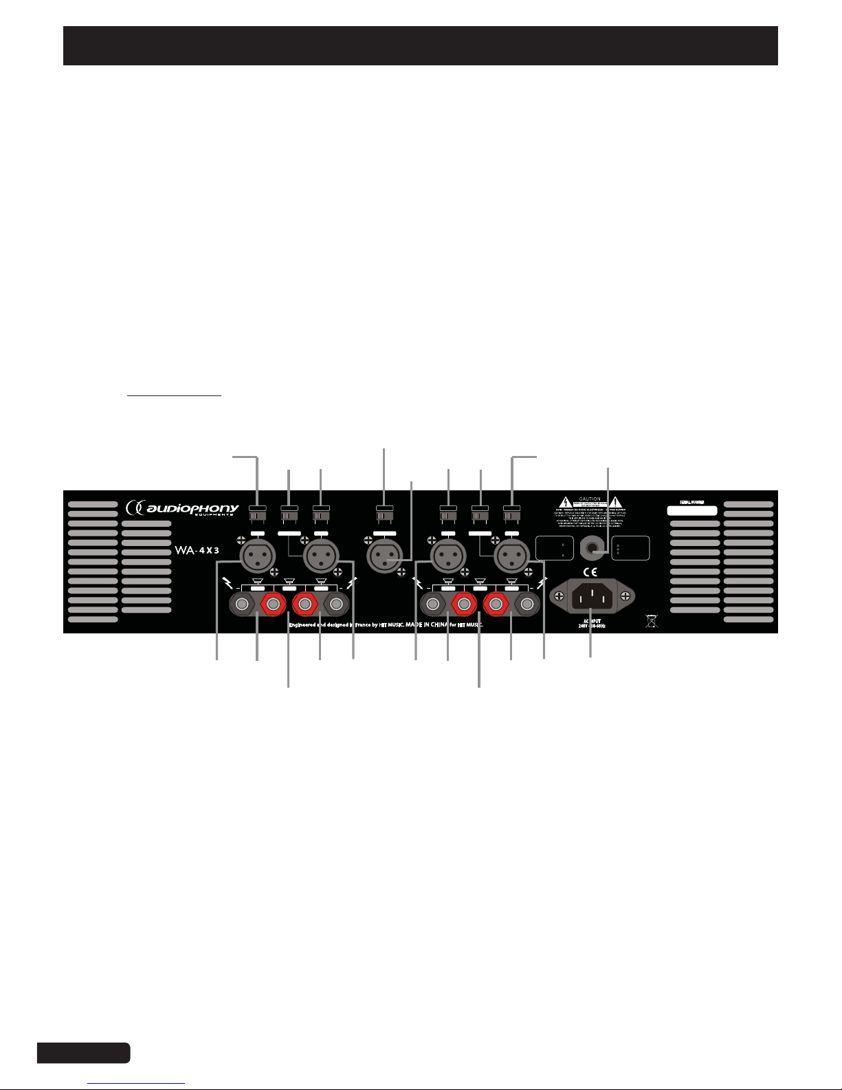
- Rear panel
[1] - Channel 4 BUS or Line mode selector
Allows you to switch between two modes:
- Line: This channel is independent
- Bus: Channel 4 signal is amplified by the 4 output channels.
Volume settings via the attenuators.
[2] - Channels 4 and 3 Bridge mode selector
Allows you to select the amplification mode: bridge or normal.
[3] - Channel 3 BUS or LINE mode selector
[4] - Channel 4 XLR inputs
Connect here the incoming signal via male XLR plug. These inputs are balanced, please refer to next
chapters for more information.
[5] - Channel 4 banana output
[6] - Channels 3 and 4 BRIDGE banana output
[7] - Channel 3 banana output
[8] - Channel 3 and Bridge XLR inputs
+
+
CH4
BRI
CH3
+
+
CH2
BRI
CH1
BRIDG E CH3CH4
BUSIN
CH2 BRIDG E CH1
BREAKER
PUSHTO RESET
INPUT
MODE
INPUT
LINE
BUS
NORMAL
BRIDGE
LINE
BUS
INPUT
LINE
BUS
INPUT
LINE
BUS
MODE
NORMAL
BRIDGE
LIMIT
ON
OFF
8 4X200W
4 4X300W
8 2X600W
(BRIDGE)
OUTPUT POW ER
NORMALMO DE:
MIN4
BRIDGE D MO DE:
MIN8
.....................
.....................
!
6
4
8
1
2
3
9
10
20
14
11 12 13
5 7
17
1916 1815

ENGLISH
WA-4x3 - 4 x 300 Watts Amplifier
Page 5
Connect here the incoming signal via male XLR socket.
[9] - LIMITER Selector
Allow you to limit the incoming signals level.
[10] - XLR Bus inputs
[11] - Channel 2 BUS or LINE mode selector
Allows you to switch between two modes:
- Line: This channel is independent
- Bus: Channel 4 signal is amplified by the 4 output channels.
Volume settings via the attenuators.
[12] - Bridge 2 mode selector
Allows you to select the amplification mode: bridge or normal.
[13] - Channel 1 BUS or LINE mode selector
[14] - Circuit-breaker
[15] - Channel 2 XLR inputs
Connect here the incoming signal via male XLR socket.
[16] - Channel 2 banana output
[17] - BRIDGE 1 banana output
[18] - Channel 1 banana output
[19] - Channel 1 and Bridge XLR inputs
Connect here the incoming signal via male XLR socket.
[20] - Power input socket
Please make sure the voltage delivered by the electrical outlet is compatible with your device, then
connect the supplied power cord.

ENGLISH
WA-4x3 - 4 x 300 Watts Amplifier
Page 6
4 - Getting started
4 - 1 - Mode selection
Three-position selectors are located at the rear of your amplifier, allowing you to switch between three
modes: Stereo, Parallel and Bridge. The default configuration is Stereo.
- 4x4 Ohms Mode (line):
Both channels are amplified independently. The 4 attenuators (front panel) also act independently.
In stereo mode, the minimum load impedance is 4 Ohms (4x300W).
Connect your mixing desk to XLR inputs 1, 2, 3 and 4 of your WA-4x3 amplifier, while your speaker
will be connected to the 4 banana outputs
Diagram:
+
+
CH4
BRI
CH3
+
+
CH2
BRI
CH1
BRIDG E CH3CH4
BUSIN
CH2 BRIDG E CH1
BREAKER
PUSHTORESET
INPUT
MODE
INPUT
LINE BUS
NORMAL
BRIDGE
LINE BUS
INPUT
LINE BUS
INPUT
LINE BUS
MODE
NORMAL
BRIDGE
LIMIT
ON OFF
84X200W
44X300W
82X600W
(BRIDGE)
OUTPUT POWER
NORMALMODE:
MIN4
BRIDGED MODE:
MIN8
.....................
.....................
MODE
NORMAL
BRIDGE
MODE
NORMAL
BRIDGE
Output 1
300W
4 Ohms
Output 2
300W
4 Ohms
Output 3
300W
4 Ohms
Output 4
300W
4 Ohms

ENGLISH
WA-4x3 - 4 x 300 Watts Amplifier
Page 7
- Stereo + Sub mode:
In this mode, channels 3 and 4 signal is stereo while channel 1 is bridged-mono amplified.
The minimum impedance load is 2x8 Ohms (2x200W) + 1x8 Ohms mono (1x600W).
Connect your mixing desk to stereo inputs of your amplifiers and to the bridge input.
Connect your speakers to the 3 banana outputs as described below.
Diagram:
+
+
CH4
BRI
CH3
+
+
CH2
BRI
CH1
BRIDG E CH3CH4
BUSIN
CH2 BRIDG E CH1
BREAKER
PUSHTORESET
INPUT
MODE
INPUT
LINE BUS
NORMAL
BRIDGE
LINE BUS
INPUT
LINE BUS
INPUT
LINE BUS
MODE
NORMAL
BRIDGE
LIMIT
ON OFF
84X200W
44X300W
8 2X600W
(BRIDGE)
OUTPUT POWER
NORMALMO DE:
MIN4
BRIDGED MO DE:
MIN8
.....................
.....................
MODE
NORMAL
BRIDGE
MODE
NORMAL
BRIDGE
Output 1
200W
8 Ohms
Output 2
200W
8 Ohms
Output 3
600W
8 Ohms

ENGLISH
WA-4x3 - 4 x 300 Watts Amplifier
Page 8
- Bus Mode:
In this mode, the signal sent to the Bus input is amplified by all 4 output channels. The minimum
impedance load is 8 Ohms (4x200W). Connect your mixing desk to the bus input of your amplifier,
while your speakers will be connected to the 4 banana outputs.
Diagram:
+
+
CH4
BRI
CH3
+
+
CH2
BRI
CH1
BRIDGE CH3CH4
BUSIN
CH2 BRIDGE CH1
BREAKER
PUSHTO R ESET
INPUT
MODE
INPUT
LINE BUS
NORMAL
BRIDGE
LINE BUS
INPUT
LINE BUS
INPUT
LINE BUS
MODE
NORMAL
BRIDGE
LIMIT
ON OFF
84X200W
44X300W
82X600W
(BRIDGE)
OUTPUT POWE R
NORMALMODE:
MIN4
BRIDGED MODE:
MIN8
.....................
.....................
INPUT
LINE
BUS
INPUT
LINE
BUS
INPUT
LINE
BUS
INPUT
LINE
BUS

ENGLISH
WA-4x3 - 4 x 300 Watts Amplifier
Page 9
- Bridge mode:
This mode adds up the amplification channels to get the maximum possible power. The incoming
signal must be received via channel 1 and 3 but the attenuators must also be configured identically
for the two channels to operate properly. In this mode, the minimum impedance load is 8 Ohms.
Connect your mixing desk to the XLR input 1 and/or 3 of your amplifier while your speakers will be
connected to the bridged banana outputs.
Diagram:
+
+
CH4
BRI
CH3
+
+
CH2
BRI
CH1
BRIDGE CH3CH4
BUSIN
CH2 BRIDGE CH1
BREAKER
PUSHTORESET
INPUT
MODE
INPUT
LINE BUS
NORMAL
BRIDGE
LINE BUS
INPUT
LINE BUS
INPUT
LINE BUS
MODE
NORMAL
BRIDGE
LIMIT
ON OFF
84X200W
44X300W
82X600W
(BRIDGE)
OUTPUT POWER
NORMALMODE:
MIN4
BRIDGED MODE:
MIN8
.....................
.....................
MODE
NORMAL
BRIDGE
MODE
NORMAL
BRIDGE
Output 1
600W
8 Ohms
Output 2
600W
8 Ohms

ENGLISH
WA-4x3 - 4 x 300 Watts Amplifier
Page 10
4 - 2 Protection systems
Because Audiophony knows what sound professionals need, your WA-4x3 are equipped with many
protection systems to guarantee the best possible lifespan for the internal components of your
amplifiers and all devices connected to their outputs.
- ACL (Active Clip Limiting)
The ACL system triggers when the amplifier has reached its full capacity or when the Clip threshold
has been reached. The Clip LED is lit continously to indicate the ACL is activated. The gain of each
channel is automatically reduced to protect the speakers from excessive sound levels which may
result in severe damages. The ACL activates during uncontrolled microphone feedbacks, incorrect
gain settings or failure of your amplifier internal components. Only excessive sound levels will trigger
this protection system.
- IGM (Instantaneous Gain Modulation)
The IGM system allows the amplifier to operate safely with load impedances close or equal to 2
Ohms. In case of excessively low load impedances, the IGM system will automatically adapt the
gain to a safe value. The IGM system is similar to the ACL: it is totally transparent most of the time
and only triggers in some situations. If the load impedance remains too low, the output relays will
deactivate the rear connectors.
- SoftStart system
Upon activation of your amplifier or activation of one of the protection system, the Softstart system
will slowly increase the output so the speakers will not have to deal with sudden peaks.
- Thermal protection
The thermal protection circuit will open output relays in case of excessively high temperature.
The Protect LED lights up during this process. In the power transformer temperature gets too high,
its temperature sensor will disconnect all power outputs, The Protect and Clip LEDs will light up while
the ON LED lights off. Cooling fans will continue operating at low speed and your amplifier will be
fully functional again once an acceptable temperature has been reached.
- Short-circuits
This protection takes effect upon detection of a short-circuit via one of the output (defective
loudspeaker, poorly isolated speaker cable, etc.).
This system detects short-circuits such as excessively low impedances and reduce the voltage
output of your amplifier to prevent the destruction of power transistors.
Affected outputs will be disconnected by the thermal protection system if the short-circuit continues.
- DC Offset protection
The output relays will open automatically to prevent damage to your speakers if one of the channels
detects direct current via one of its output connectors.
- Ultra-low frequencies (<20 Hz)
The internal high-pass filter gets rid off ultra-low frequencies. However, if such frequencies were to be
detected, a relay will eliminate them.

ENGLISH
WA-4x3 - 4 x 300 Watts Amplifier
Page 11
5 - Technical specifications
Power output: RMS at 8 Ohms 4 x 200 W
Power output: RMS at 4 Ohms 4 x 300W
Power output: RMS stereo-bridged at 8 Ohms 2 x 600W
Power output: RMS 1 bridged et 2 stereo at 8 Ohms 1x 600 + 2x200 W
Sensitivity at 8 Ohms rated power 0,775mV
Frequency response (1W) 20Hz - 25KHz (+0dB, -0,5dB)
Frequency response 20Hz at 20 Khz
Phase response (1W) 20Hz - 20KHz (+10°, -20°)
Signal to noise ratio below rated power A-weighted > 100 dB
THD (20Hz - 20KHz) < 0,1%
Intermodulation Distortion (IMD) at 60 Hz and 7 kHz
at 4:1, from full rated output to -35dB
< 0,05%
Damping factor at 8 Ohms from 20Hz to 400Hz > 200
Input impedance (nominally balanced) 20 KOhms
Input impedance (nominally unbalanced) 10 KOhms
Max load impedance, 4 channels 4 and 8 Ohms
Max. load impedance, stereo bridged 8 Ohms
Power supply 220 - 240V ; 50 - 60Hz
AC line current
8A (both amplifiers do not consume
more than 90W when inactive)
Cooling system Front to rear forced ventilation
Fans Proportional speed
Dimensions 483 x 375 x 89 mm
Net weight 16 Kg
Shipping weight 19 Kg

Because AUDIOPHONY® takes the utmost care in its products to make sure you only get the best possible quality, our products are subjects
to modifications without prior notice. That is why technical specifications and the products physical configuration might differ from the
illustrations.
Make sure you get the latest news and updates about the AUDIOPHONY® products on www.audiophony.com/en/
CONTEST® is a trademark of HITMUSIC S.A. - Zone Cahors sud - 46230 FONTANES - FRANCE
 Loading...