

Page 1
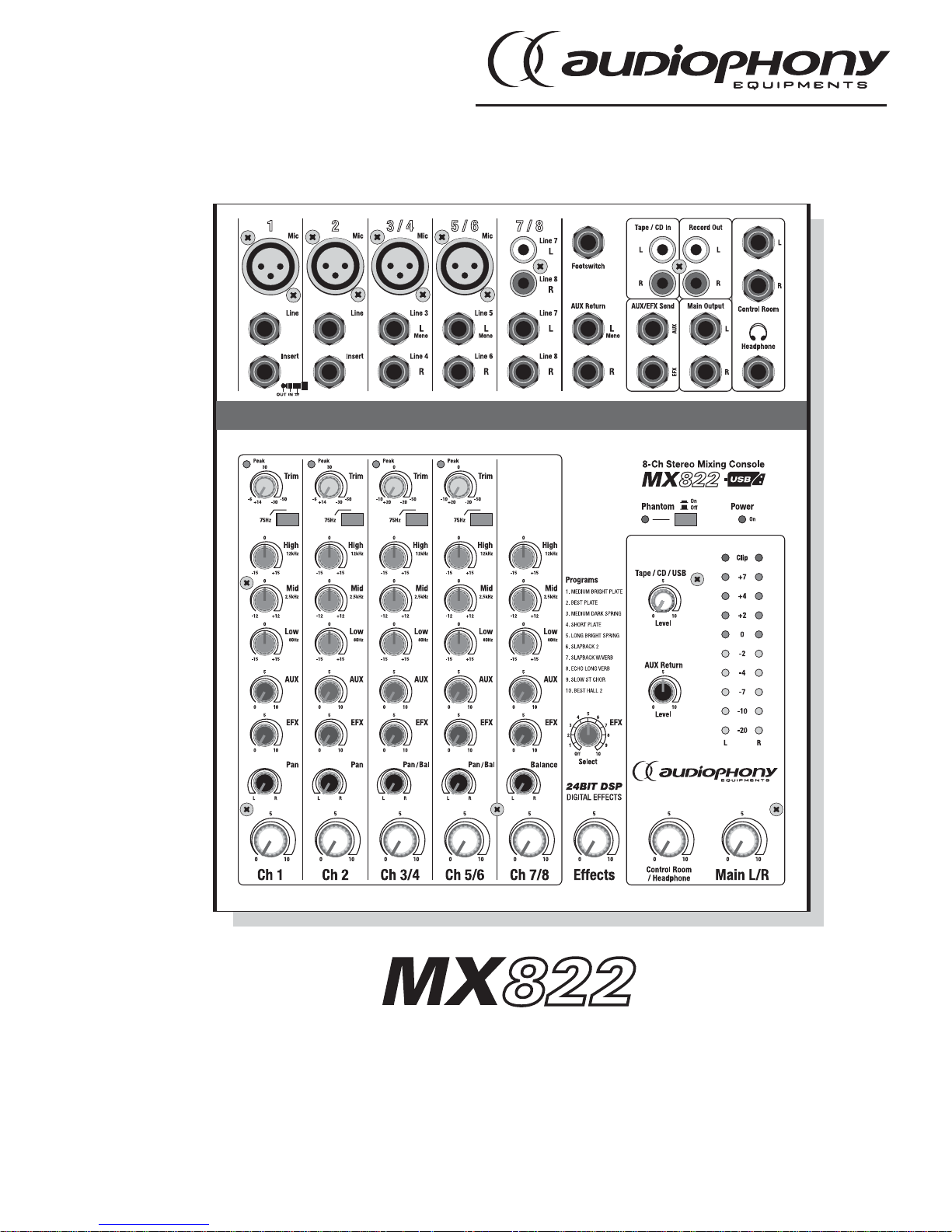
USER GUIDE
9558 - September 2009 Version 1.0
Live mixer with 4 mics + 5 lines + 24-bit DSP, 10 FX and USB port
Page 2

MX822 - Live mixer with 4 mics + 5 lines + 24-bit DSP, 10 FX and USB port
Page 2
English
Page 3
MX822 - Live mixer with 4 mics + 5 lines + 24-bit DSP, 10 FX and USB port
Page 3
English
1 - Safety information
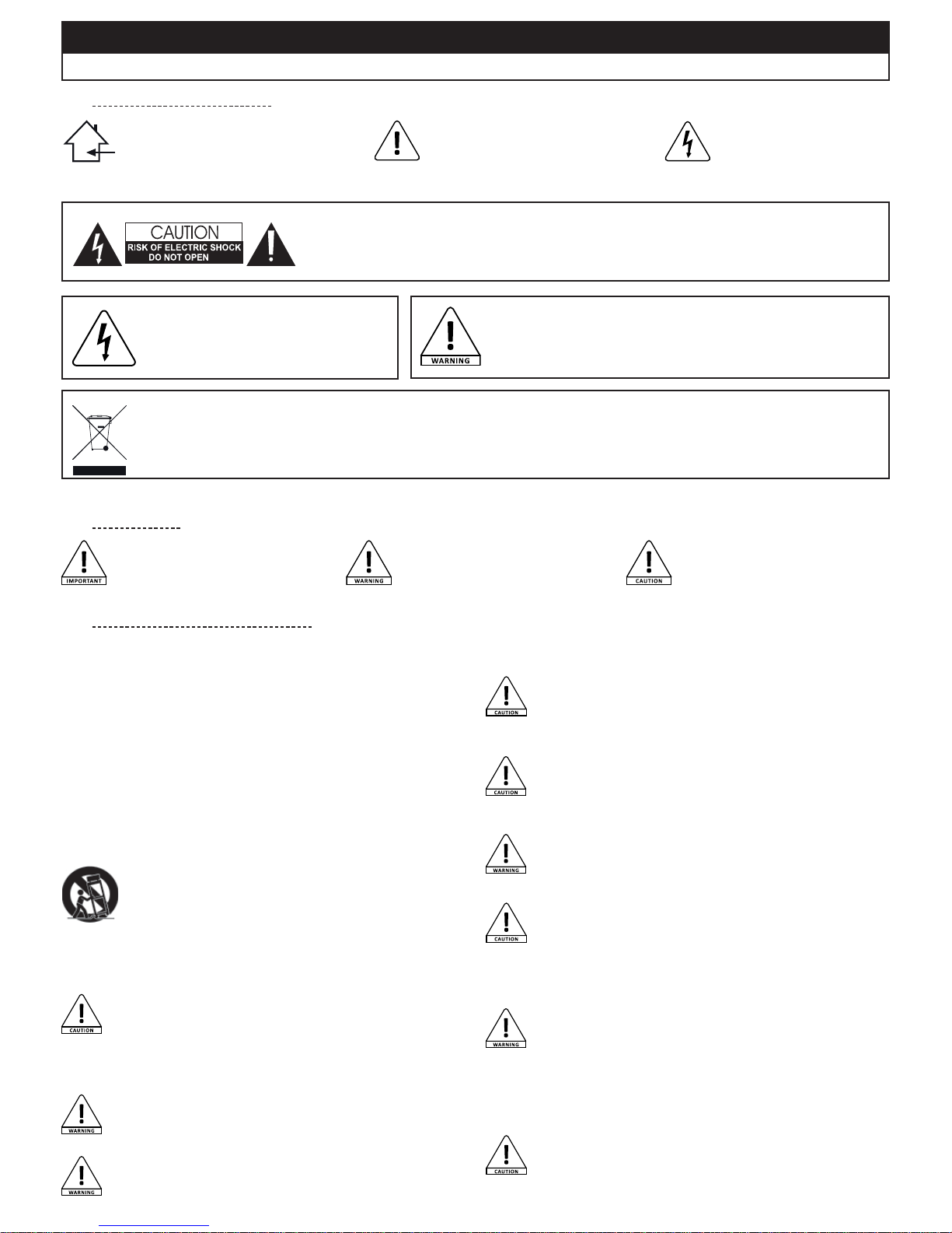
This symbol signals an important safety
precaution.
The CAUTION symbol signals a risk of
product deterioration.
The WARNING symbol signals a risk to the
user’s physical integrity.
The product may also be damaged.
1.1 - Important safety information
1.2 - Symbols used
This product contains non-isolated electrical components. Do
not undertake any maintenance
operation when it is switched on as
it may result in electric shock.
Any maintenance procedure must be performed by a CONTEST authorised technical
service. Basic cleaning operations must thoroughly follow our safety instructions.
This unit is intended for indoor use only. Do not
use it in a wet, or extremely cold/hot locations.
Failure to follow these safety instructions could
result in fire, electric shock, injury, or damage to
this product or other property.
CAUTION: This unit contains no user-serviceable parts. Do not open the housing or attempt any
maintenance by yourself. In the unlikely even your unit may require service, please contact your nearest
dealer.
Sound levels
Our audio solutions deliver important sound pressure levels (SPL) that can be
harmful to human health when exposed during long periods. Please do not stay
in close proximity of operating speakers.
Risk of electrocution
To prevent the hazard of electric shocks, do not
use extension cords, multi-socket or any other
connection system without making sure metal
parts completely are out of reach.
Recycling your device
• As HITMUSIC is really involved in the environmental cause, we only commercialise clean, ROHS compliant products.
• When this product reaches its end of life, take it to a collection point designated by local authorities. The separate collection and
recycling of your product at the time of disposal will help conserve natural resources and ensure that it is recycled in a manner that
protects human health and the environment.
1.3 - Instructions and recommendations
11 - Power cords protection:
Power-supply cords should be routed so that they are not likely to be walked
on or pinched by items placed upon or against them, paying particular
attention to cords at lugs, convenience receptacles and the point where
they exit from the fixture.
12 - Cleaning precautions:
Unplug the product before attempting any cleaning operation. This
product should be cleaned only with accessories recommended by the
manufacturer. Use a damp cloth to clean the surface. Do not wash this
product.
13 - Long periods of non use:
Disconnect the unit’s main power during long periods of non use.
14 - Liquids or objects penetration:
Do not let any object penetrate this product as it may result in electric
shock or fire.
Never spill any liquid on this product as it may infiltrate the electronic
components and result in electric shock or fire.
15 - This product should be serviced when:
Please contact the qualified service personnel if :
- The power cord or the plug has been damaged.
- Objects have fallen or liquid has been spilled into the appliance.
- The appliance has been exposed to rain or water.
- The product does not appear to operate normally.
- The product has been damaged.
16 - Inspection/maintenance: Please do not attempt any inspection or maintenance
by yourself. Refer all servicing to qualified personnel.
17 - Operating environment:
Ambient temperature and humidity: +5 - +35°C, relative humidity must be
less than 85% (when cooling vents are not obstructed).
Do not operate this product in a non-ventilated, very humid or warm place.
1 - Please read carefully:
We strongly recommend to read carefully and understand the safety instructions
before attempting to operate this unit.
2 - Please keep this manual:
We strongly recommend to keep this manual with the unit for future reference.
3 - Operate carefully this product:
We strongly recommend to take into consideration every safety instruction.
4 - Follow the instructions:
Please carefully follow each safety instruction to avoid any physical harm or property
damage.
5 -Avoid water and wet locations:
Do not use this product in rain, or near washbasins or other wet locations.
6 - Installation :
We strongly encourage you to only use a fixation system or support
recommended by the manufacturer or supplied with this product.
Carefully follow the installation instructions and use the adequate tools.
Always ensure this unit is firmly fixed to avoid vibration and slipping
while operating as it may result in physical injury.
7 -Ceiling or wall installation:
Please contact your local dealer before attempting any ceiling or wall installation.
8 - Ventilation:
The cooling vents ensure a safe use of this product, and avoid any
overheating risk.
Do not obstruct or cover these vents as it may result in overheating and
potential physical injury or product damage. This product should never
been operated in a closed non-ventilated area such as a flight case or a rack, unless
cooling vents are provided for the purpose .
9 - Heat exposure:
Sustained contact or proximity with warm surfaces may cause overheating
and product damages. Please keep this product away from any heat source
such as a heaters, amplifiers, hot plates, etc...
10 - Electric power supply:
This product can only be operated according to a very specific voltage.
These information are specified on the label located at the rear of the
product.
Page 4
MX822 - Live mixer with 4 mics + 5 lines + 24-bit DSP, 10 FX and USB port
Page 4
English
Thank you for purchasing the MX822.
You are now in possession of a high-quality device which will meet your every need.
The MX822 is an orchestral mixing desk featuring a USB port and 24-bit DSP.
It is easy to use, fast, and features many functions: it is super-efficient.
The user guide you are currently reading will help you getting familiar with the many possibilites and functions offered by your MX822.
Keep it within reach during the first uses.
2 - Introduction and Installation
2.1 - Introduction
2.2 - Package contents
2.3 - Installation
Your MX822 was designed to be operated horizontally when not mounted into brackets. Please make sure your MX12/1624 does not
vibrate, or is not
being acted upon by an outside force to prevent any fall.
In the package you may find :
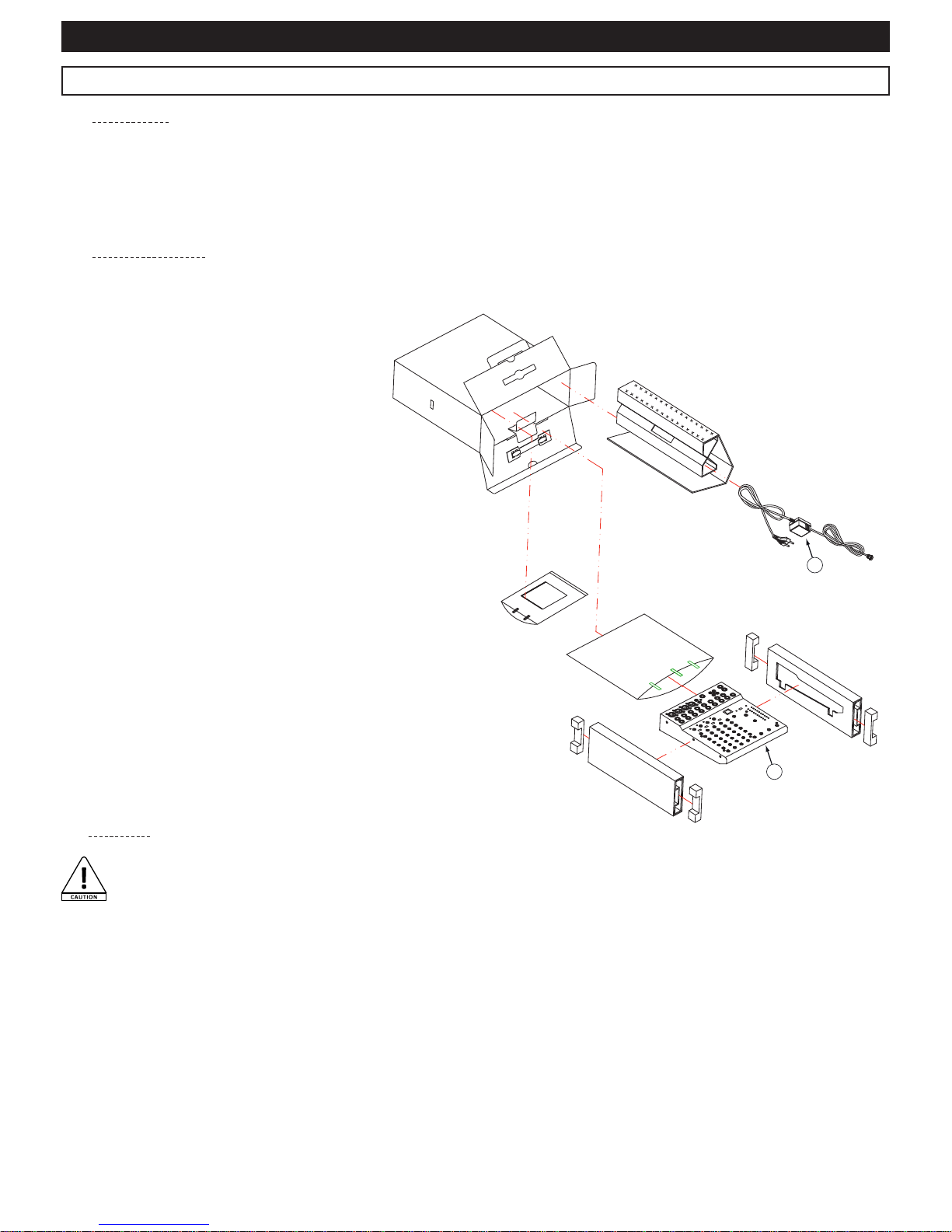
1 - Your MX822 mixing desk
2 - An external power supply
And, of course, the user guide you are currently
reading.
Please contact your retailer immediately if one or
several of these articles were to be missing.
Your console has been packed with the utmost care to prevent any transportation damage. If the package shows any sign of damage,
please make sure your console housing is in perfect condition.
1
2
Page 5
MX822 - Live mixer with 4 mics + 5 lines + 24-bit DSP, 10 FX and USB port
Page 5
English
3 - Getting started in 6 steps
Phone
Phantom power
Level meter
General
level
Mic inputs, line and music instruments
Channels level
Gain adjustment
With peak indicators
Monitor
ŵƉůŝĮĞƌ
Speakers
PAN adjustment
ƋƵĂůŝƐĂƟŽŶ
Power switch
1-3
1-6
1-6
1
1
1-4
2-3
2-4
3
4-6
2-3
2
Computer
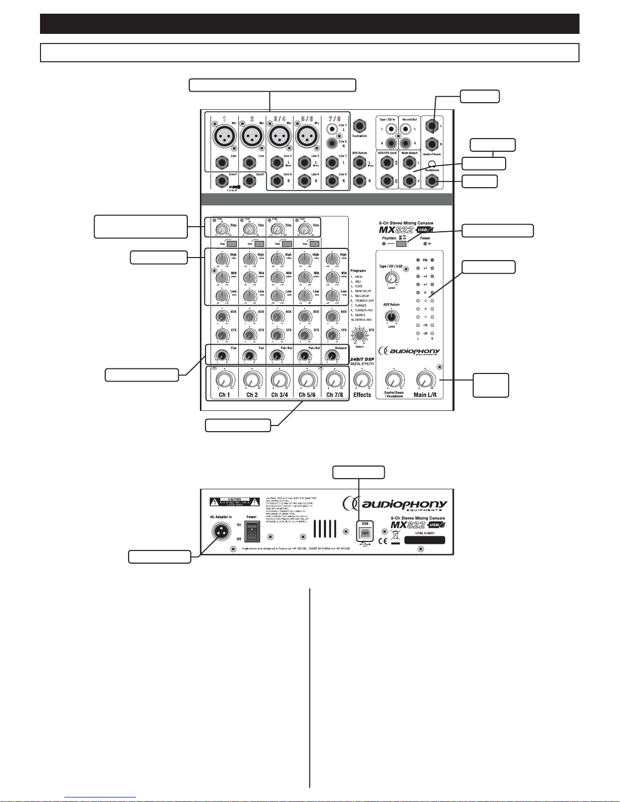
1 - Turn your console volume at the lowest.
The volume control commands are: the channel faders, gain control
knobs, ALT 3/4 faders, the main L/R fader, and the AUX/EFX Send
control knobs.
2 - Turn off any external device and connect the
microphones and instruments.
Note :
- Please refer to chapter 7 for more details about connectors
to be used.
- If connecting guitars or basses, please use direct boxes (DI).
By connecting directly these instruments, they will produce a
poor sound quality.
3 - In order to preserve your speakers, please turn on
your devices in the following order:
a - External devices
b - Your MX822
c - Power amplifiers or amplified speakers
Note :
If you are using microphones requiring a phantom power supply
unit, please turn on this power supply before turning on your
console.
Page 6
MX822 - Live mixer with 4 mics + 5 lines + 24-bit DSP, 10 FX and USB port
Page 6
English
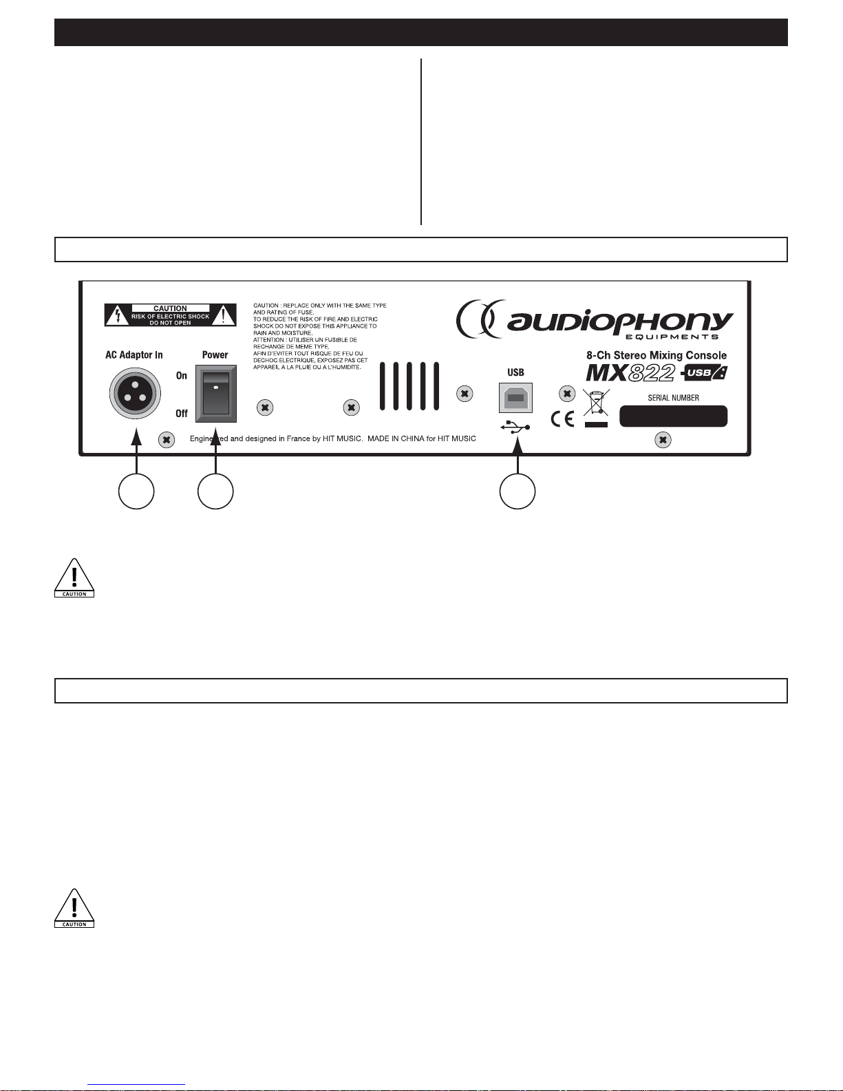
4 - Rear panel
5 - Using the USB port
4 - Adjust the gain control settings so the peak LEDs
flash momentarily during sound level peaks:
Note :
- In order to precisely configure a channel, please use the PFL
switch of said channel and adjust the gain so the LED VU meter
occasionally goes beyond O.
- The headphones output will allow you to monitor the volume
settings. This output sends the pre-fade signal (prior to any
channel settings).
1 2 3
1 - Power input socket:
Connect the power supply unit provided for the purpose.
CAUTION: Your mixing desk has been designed to use
the supplied AC adapter only. Using any other power
supply units voids the warranty.
2 - Power switch
4 - Digital audio USB input/output
The MX822 USB port will be detected automatically by your computer
(PC or MAC) as bi-directional sound card. The volume of this output
can be configured via the Tape / CD / USB fader.
The USB port of your mixing desk allows you to play files from your computer, or record the audio mix onto your computer.
The Full Duplex system allows you to simultaneously:
- Send a source from your computer to your mixing desk via multimedia softwares.
- Send a source from your mixing desk to your computer in order to record it via dedicated softwares.
- Your MX12/1624 uses a standard USB Audio Codec protocol (USB audio device), compatible with every recent and updated OS.
- This codec does not require specific drivers to be compatible with your computer.
- Connect a USB A/B cable from your computer to your mixing desk (detected as sound card) and follow your computer instructions in
order to send or receive a signal from your MX12/1624.
- The volume of the USB input/output can be configured via the Tape / CD / USB fader.
CAUTION:
- It is inadvisable to connect or disconnect a USB device when your console is activated, or playing a track from your
computer.
- You cannot connect a USB Mass Storage source (USB key, hard disks...) to this USB port.
5 -Set the MAIN L/R fader on "0".
6 - Adjust the channels levels to get the proper balancing,
then use the MAIN L/R fader to adjust the main volume.
Note :
Deactivate the channels PFL, ALT 3/4 and Tape/CD/USB switches
located below the VU meter to display the main sound levels via
the VU mete
Page 7
MX822 - Live mixer with 4 mics + 5 lines + 24-bit DSP, 10 FX and USB port
Page 7
English
6 - Description per zone
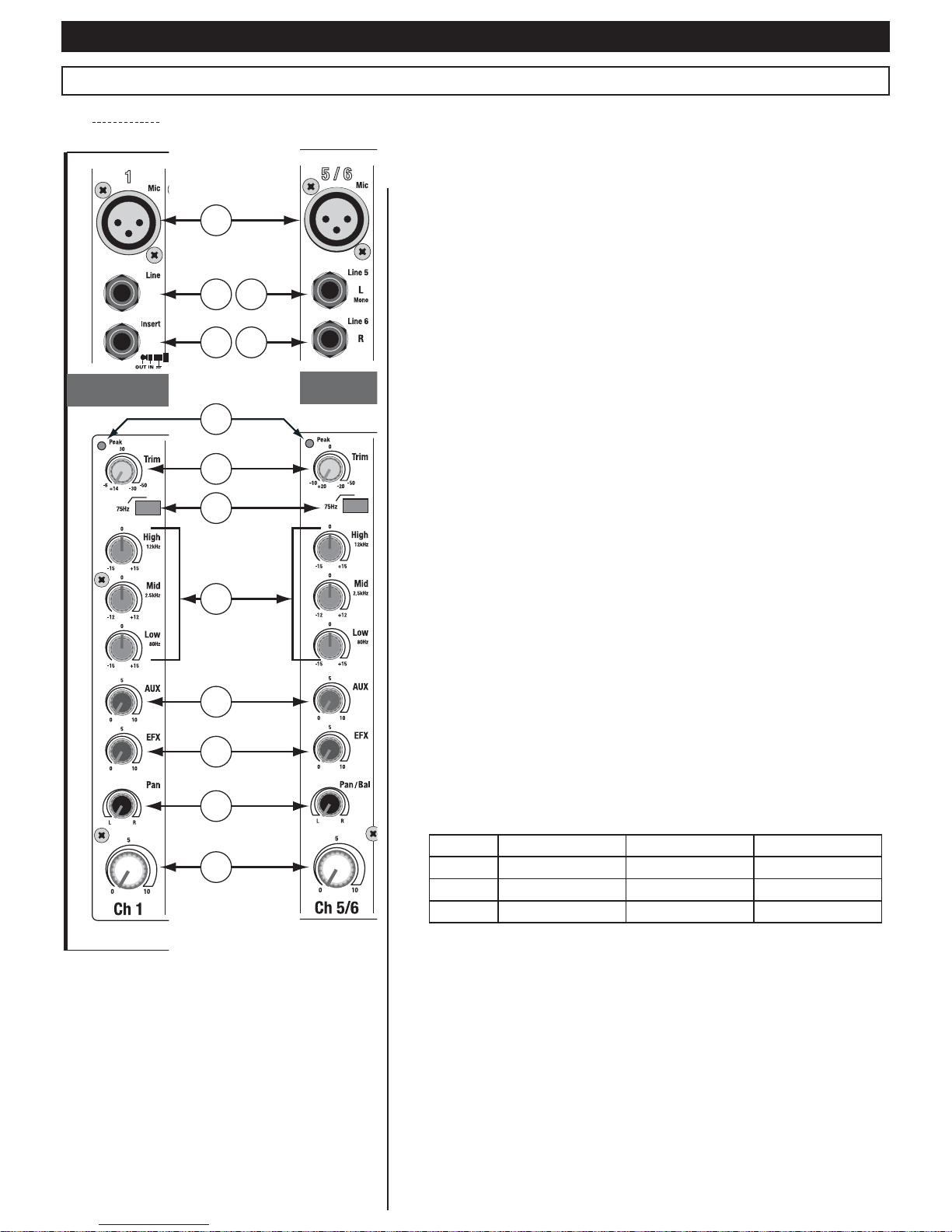
6.1 - Mono area
1 - Mic inputs:
Connect your microphones here. These microphone inputs are balanced and can
be powered up by a phantom power supply when using condenser microphones.
Please refer to chapter 7 for more details about the hardwiring of these inputs.
These inputs can also receive unbalanced signals.
2 - Line inputs:
These line-level inputs, via Jack TRS (stereo) chassis, are balanced. These inputs
can also receive unbalanced signals. Connect here your keyboards, line-level
guitar amplifiers outputs, direct boxes, etc.
Please refer to chapter 7 for more details about the hardwiring of these inputs.
3 - Insert socket:
This socket is located between the input amplifier and the high-pass filter (6).
It allows you to insert your own DSP, graphic equalizer, compressor or any other
sound processing device between the incoming signal and the sound processor
of the input.
Please refer to chapter 7 for more details about hardwiring.
4 - Peak LED:
This LED allows you to check on the sound level of the incoming signal. It lights
up when the incoming signal is just 5dB below the channel saturation threshold.
This is measured after the equalisation, and before the channel fader. This LED
should not be lit too often, using the Trim control knob allows you to decrease the
volume output of the device connected on this channel.
5 - Trim control knob:
This control knob allows you to adjust the amplfication level of the channel.
Position this fader on the left before dis/connecting any source on this channel.
This knob has two different modes of operation:
- From -30 to +14dB for the microphone input.
- From -50 to -6dB for the line level input.
Upon connection of a line level source (-10dBV or +4dBU), position this knob onto
the position matching the output level, send a signal and use the VU meter to
make sure the output level reaches 0dB.
6 - High-pass filter switch:
Once activated, this switch activates the low-pass filter. This filter allows you
to get rid of any frequence below 75Hz. Low frequencies usually carry parasitic
noises due to low quality cables or polluted environments (ground feedbacks,
etc.).
7 - Equalization area:
Each channel features a high-quality equalization for three frequencies:
Setting Range Frequency Curve type
HIGH
+/- 15 dB 12 KHz Shelving
MID
+/- 12 dB 2,5 KHz Peaking
LOW
+/- 15 dB 80 Hz Shelving
The equalizer does not have any effect when these three buttons are in the middle
position.
8 - AUX Control knobs:
These knobs allow you to adjust the signal level sent to the AUX bus.
9 - EFX control knob:
This knob allows you to adjust the signal sound level sent to the EFX bus. The
main level of this bus is controlled by the EFX Send knob. This settings takes
effect after the channel fader settings (14).
The EFX bus also powers up the built-in sound processor.
1
2
3
6
7
8
10
11
12
13
4
5
9
Page 8
MX822 - Live mixer with 4 mics + 5 lines + 24-bit DSP, 10 FX and USB port
Page 8
English
10 - Pan control knob:
This knob allows you to control the signal quantity sent to each ways
(L and R) of the Main bus. You can choose which side of the stereo
will send more signal.
If this knob is on the left e.g., the signal will be audible only on the left
side of your sound system.
11 - Channel faders:
This fader allows you to adjust the main channel volume by controlling
the signal quantity sent to the Main and EFX buses. This is especially
useful to balance your different sources such as instruments, voices,
etc.
We strongly recommend to position this fader on its lowest volume
(-) when a channel is not used, in order to prevent parasitic noises.
12 - Line level inputs (L MONO) (channels 3 and 5) via
Jack chassis:
Line-level inputs via Jack TS chassis (Mono). These inputs are
unbalanced. A signal sent to these inputs will also be sent to both
channels 9 and 11.
13 - Line level inputs (R) (canaux 4 et 6) via Jack chassis:
Line-level inputs via Jack TS chassis (Mono). These inputs are
unbalanced. when a signal is detected on these inputs, the concerned
area becomes stereo. This input affects the right side of your stereo
signal.
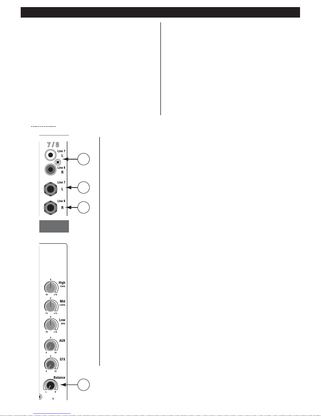
6.2 - Stereo area
1
2
3
4
1 - Stereo input:
Unbalanced input via RCA chassis.
2 and 3 - Stereo input:
Unbalanced input via Jack chassis.
Note : If connecting a source via the RCA inputs, do not connect another source via these Jack inputs.
4 - Balance control knob:
Allows you to adjust the balance. Unlike mono areas, stereos areas are double, this knob allows
you to adjust the signal quantity sent to both sides of this area before being sent to the Main bus.
Note :
- This zone do not have any gain settings.
- Other settings are similar to mono areas.
Page 9
MX822 - Live mixer with 4 mics + 5 lines + 24-bit DSP, 10 FX and USB port
Page 9
English
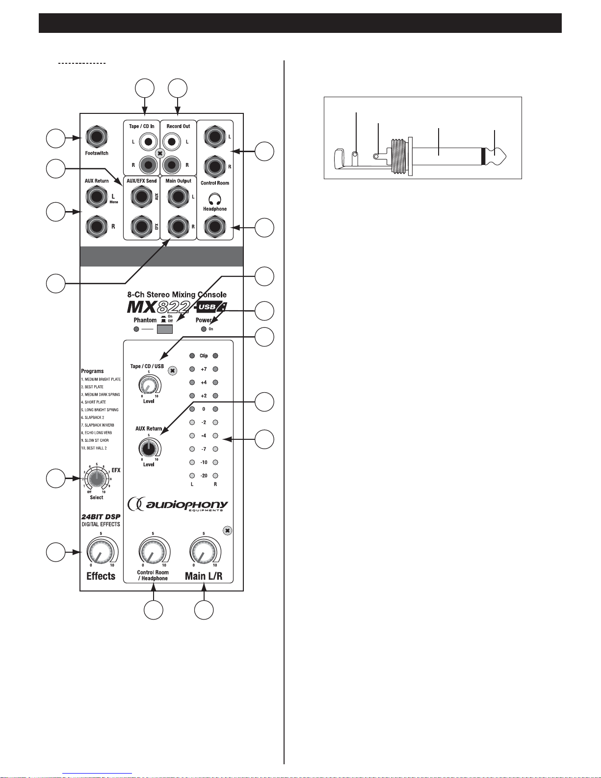
6.3 - Master area
1
2
3
4
5
6
7 8
9
10
11
12
13
14
15
16
17
1 - Footswitch connector:
This Jack TS connector allows you to connect a footswitch in order to
use the effects processor remotely. It is hardwired as follows:
2 - - AUX/EFX Send output:
- AUX Output: Unbalanced signal from the AUX bus. Connect here a
monitoring system or effects processor.
- EFX Output: Unbalanced signal from the EFX bus. Connect here an
external effects processor or monitoring system.
Using this output deactivates the internal multi-effects.
3 - AUX Return L MONO and R inputs:
Line level mono Jack chassis. Signals received via these inputs are sent
to the AUX and Main L/R busses. These inputs are mainly used to receive
signals from an external effect (Reverb, Delay, etc.).
Note : These inputs can also be used like a standard line level aux
input. By connecting the L Mono chassis only, the signal will be sent
to both L and R sides.
4 - Main Output:
Balanced Jack TRS outputs. Signals sent to these outputs are the
cimbination of all incoming signals. Connect here the main amplification
system of your installation.
5 - EFX Select control knob:
Allows you to select effects. The processor features 10 factory presets,
this list is exhaustively detailed in chapter X. The processor is deactivated
when on "OFF".
6 - EFX control knob:
Allows you to adjust the signal level sent from the effects processor to
the Main bus.
7 - Control Room / Headphone control knob:
Allows you to adjust the sound levels of the Control Room and
headphones output.
8 - Main L/R control knob:
Allows you to control the volume output of all signals sent to the Main
Output (4).
9 - LED VU meter:
Double vertical VU meter with 10 LEDs. Allows you to visualise the main
volume output or per zone depending on the switches combination used
as explained previously. Level "0" refers to +4dB for outputs for which
+4dB is the nominal level.
10 - AUX Return control knob:
Allows you to control the signal quantity sent from the effect processor
to the AUX bus.
11 - Tape/CD / USB control knob:
This knob allows you to adjust the volume of the Tape/CD In and USB
inputs.
The USB connector is located on the rear panel. Please refer to chapter
Tip
Tip
Pole 2
Sleeve
Sleeve
Pole 1 / Ground
Page 10

MX822 - Live mixer with 4 mics + 5 lines + 24-bit DSP, 10 FX and USB port
Page 10
English
5 for more details about the USB port.
12 - Power LED:
Lights up when your console is activated.
13 - Phantom switch:
Activates the phantom power supply for XLR microphone inputs.
Condenser microphones require a phantom power supply.
Note : Your console delivers +48 Volts between pins 2 and 3 of
XLR sockets once the phantom power supply has been activated.
14 - Headphone output:
Allows you to connect monitoring headphones.
15 - Control Room outputs:
Balanced Jack TRS outputs. Signals sent to these inputs depend on
the PFL switches. The sound levels of these outputs can be adjusted
via the Control Room / Headphone knob.
16 - Record Out:
Unbalanced signal via RCA connectors. The pre-faded signal sent
to this output comes from the Main bus. Connect here any line-level
recorder.
17 - Tape IN/CD input:
Line level input via RCA chassis. Connect a DAT or CD player here.
Note : This input volume can be adjusted via the Tape / CD / USB
(13) knob of the Master area.
Page 11
MX822 - Live mixer with 4 mics + 5 lines + 24-bit DSP, 10 FX and USB port
Page 11
English
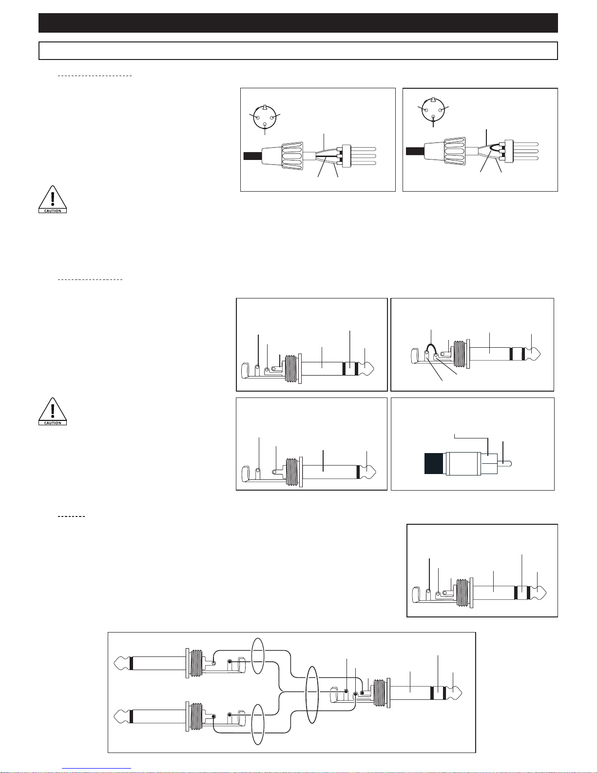
The unbalanced insert point allows you to insert limiters, compressors, special equalizers or any
other processors on the signal path. The insert (Stereo Jack 6.35 mm) features a closed contact.
When inserting a Jack plug into this connector, the signal path will be cut. The channel signal is
available via the TIP, while the signal feedback is available via the RING.
The mass is transmitted via the body.
The outgoing signals can be used as direct pre-fade and pre-equalizer outputs (the tip and the ring
will then be short-circuited to prevent any signal path interruption).
You will be required to use Y-cables (as described below) if using devices with separated incoming
and outgoing signals.
Ring
Ring
Return (in)
Tip
Tip
Send (out)
Sleeve
Sleeve
Ground/Shield
Insert plug on TRS jack
Sleeve
Sleeve
Output
Input
Ground/Shield
Ring
Ring
Return (in)
Tip
Tip
Send (out)
Mono line-level inputs feature Jack or RCA chassis
onto which you can add balanced or unbalanced
signals.
These inputs can be used to connect synthetisers,
drum machines, direct boxes, etc.
When using unbalanced sources, the ring must be
connected to the body.
RCA inputs can also be used to connect other
sources: CD player, MP3 player, etc.
CAUTION: Please turn the gain settings
of each affected channel to their
minimum before connecting any linelevel signal in order to prevent overloads
and damages to your amplification system.
7.1 - Microphone inputs
7.2 - Line-level inputs
7.3 - Inserts
Microphone inputs feature XLR chassis able to
receive both balanced and unbalanced signals.
These inputs are dedicated to low-level signals.
Connect here low impedance dynamic or condenser
microphones.
These inputs deliver a +48V current required for
condenser microphones once the phantom power
supply has been activated.
CAUTION: Do NOT use balanced sources
once the phantom power supply has
been activated as the voltage delivered
via pins 2 and 3 may cause severe damages to your devices. If using balanced dynamic microphones, please make sure they
are compatible with phantom power supplies.
2 = Hotspot (+)
2
3
1
3 = Coldspot (-)
1 = Ground
Balanced
2 = Hotspot (+)
2
3
1
Shunt between
1 et 3 pins
1 = Ground
Unbalanced
Unbalanced TS
Ring
Ring
Coldspot (-)
Tip
Tip
Hotspot (+)
Sleeve
Sleeve
Ground / Shield
Balanced
Ring
Tip
Tip
Hotspot (+)
Sleeve
Sleeve
Ground / Shield
Shunt between
ring and sleeve
Unbalanced TRS
Tip
Tip
Signal
Sleeve
Sleeve
Ground / Shield
Center
Signal
Sleeve
Ground / Shield
Unbalanced RCA
7 - More about connectors
Page 12
MX822 - Live mixer with 4 mics + 5 lines + 24-bit DSP, 10 FX and USB port
Page 12
English
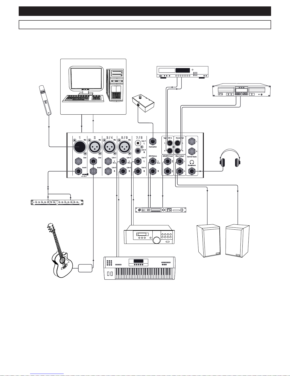
8 - Circuit principle: home studio
Phone
Powered monitor
īĞĐƚƉƌŽĐĞƐƐŽƌ
ƌƵŵŵĂĐŚŝŶĞ
Keyboard
ŽŵƉƌĞƐƐŽƌ
DŝĐƌŽƉŚŽŶĞ
USB
ŽŵƉƵƚĞƌ
&ŽŽƚͲƐǁŝƚĐŚ
CD Player
ZĞĐŽƌĚĞƌ
ůĞĐƚƌŽĂĐŽƵƐƟĐŐƵŝƚĂƌ
Dibox
Page 13
MX822 - Live mixer with 4 mics + 5 lines + 24-bit DSP, 10 FX and USB port
Page 13
English
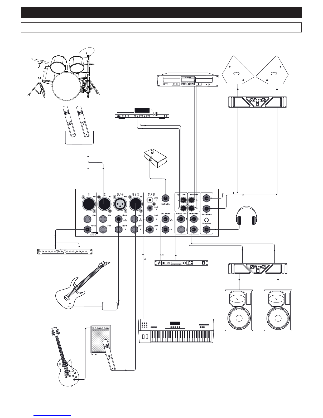
9 - Circuit principle: live installation
Phone
Bass
Dibox
īĞĐƚƉƌŽĐĞƐƐŽƌ
ƌƵŵ
<ĞLJďŽĂƌĚ
^ƉĞĂŬĞƌ
DŽŶŝƚŽƌ
ƐƉĞĂŬĞƌ
^ƉĞĂŬĞƌ
ŵƉůŝĮĞƌ
ŵƉůŝĮĞƌ
ŽŵƉƌĞƐƐŽƌ
DŝĐƌŽƉŚŽŶĞ
DŝĐƌŽƉŚŽŶĞ
&ŽŽƚͲƐǁŝƚĐŚ
WůĂLJĞƌ
ZĞĐŽƌĚĞƌ
'ƵŝƚĂƌ
Page 14
MX822 - Live mixer with 4 mics + 5 lines + 24-bit DSP, 10 FX and USB port
Page 14
English
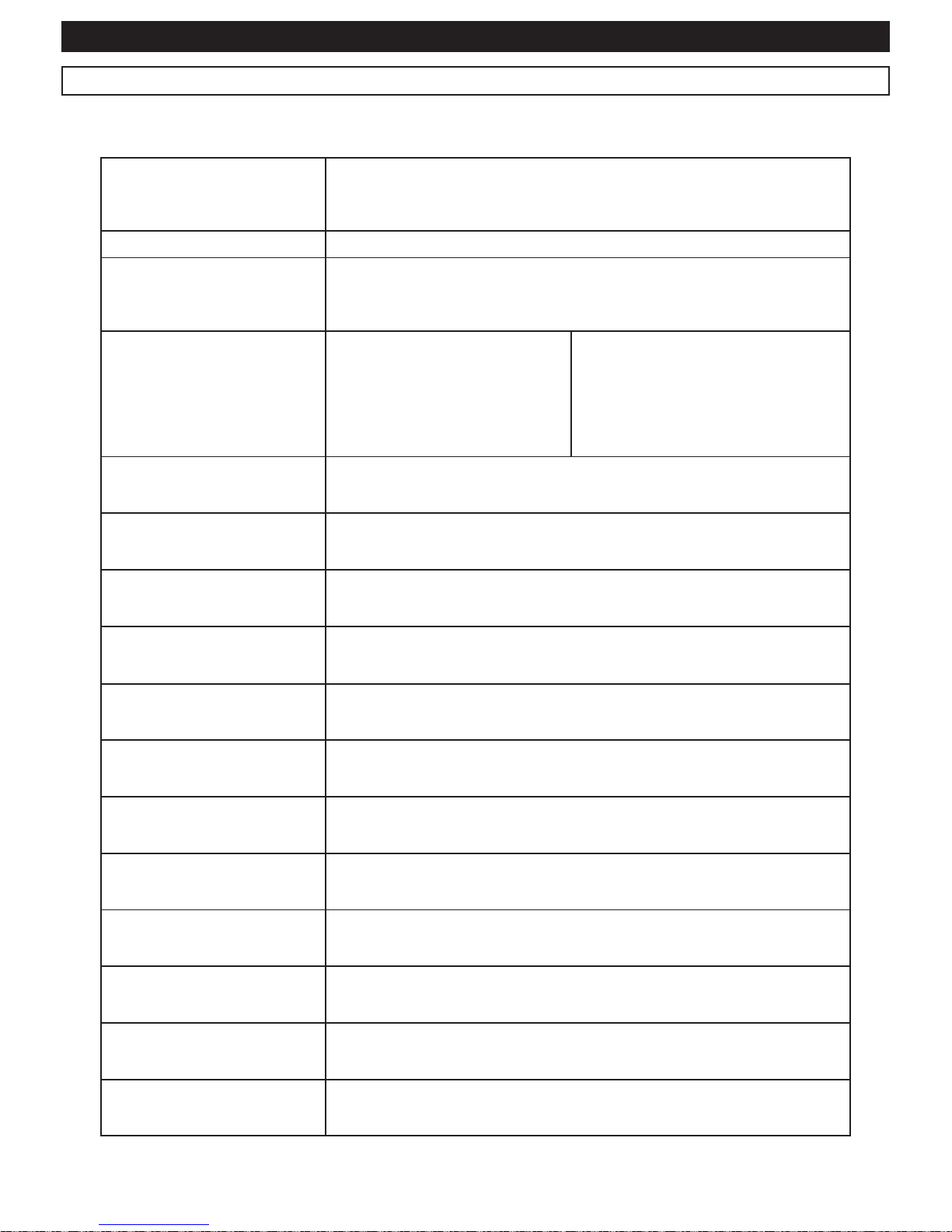
10 - Technical specifications
0dB = 0,775mV / 0dBV = 1Vrms
Max. output levels
+20dB (Main L/R)
+20dB (AUX/EFX Send, Control Room)
+20dB (Insert)
More than 100 mW (Headphone) @ 33
T.H.D Lower than 0,1% @ +14dB 20Hz at 20 kHz (Main L/R, AUX/EFX Send, Control Room)
Humming and noises
(Rs = 150)
-127dB : Equivalent input noise (EIN), -95dB residual noise (Main L/R, AUX/EFX Send,
Control Room)
- 88dB (Main L/R, , AUX/EFX Send, Control Room)
*Fader Main L/R at 0 and all channel faders at their minimum
Max. input voltage
66dB from Mic Input to Main L/R
60dB from Mic Input to AUX
66dB from Mic Input to EFX (REV)
76dB from Mic Input to Control Room
L/R
58,2dB from Mic Input to Record Out
46dB from Line Input to Main L/R
46dB from Line Input to AUX
46dB from Line Input to EFX (REV)
56dB from Line Input to Control Room L/R
36dB from Line Input (stéréo) to Main L/R
6dB from AUX Return to Main L/R
16dB from Tape In to Main L/R
Crosstalk (at 1 KHz) -70dB between input channels; -70dB between input/output channels
Gain control for mono inputs Range of 44dB (-50dB ~ -6dB) ; (-30dB ~ +14dB)
Gain control for stereo inputs Range of 40dB (-20dB ~ +20dB)
Input channels equalization
HIGH : 12kHz ; Shelving
MID : 2,5kHz ; Peaking
LOW : 80Hz ; Shelving
LED VU meter 2x10 LEDs segments for Main L/R
Built-in DSP
10 Presets
Optional footswitch to control remotely
Channel indicators Peak indicator for each pre-faded channel reaching -5dB below the clip limit
Phantom power supply +48V DC, activated via the Phantom switch in the Master area
Supplied accessories AC adapter: Ref. PA-M822 - 25W
Power supply 230V AC - 50Hz
Power consumption 25W max.
Weight 2.4 Kg
Page 15
MX822 - Live mixer with 4 mics + 5 lines + 24-bit DSP, 10 FX and USB port
Page 15
English
Input connectors: Types, Levels and Impedances
Input connector Input impedance Nominal impedance Input level Type of connector
Mic in mono areas
4k 50 ~ 600 -50dB Balanced 3-pin XLR
Line
10k 600 -30dB Balanced Jack (TRS)
Mic in stereo areas
3k 600 -44dB Balanced 3-pin XLR
Stereo inputs
5k 600 -20dB Unbalanced Jack (TS)
Insert in mono area
10k 600 0dB Balanced Jack (TRS)
Tape In
10k 600 -10dBV RCA socket
Output connectors: Types, Levels and Impedances
Output connector Output impedance Nominal impedance Output level Type of connector
Main L/R
240 20k +4dB Unbalanced Jack (TS)
Control Room
75 10k +4dB Unbalanced Jack (TS)
AUX/EFX Send
75 600 +4dB Unbalanced Jack (TS)
Insert tranches mono
600 10k 0dB Balanced Jack (TRS)
Record Out
600 10k -10dBV RCA socket
Phone Output
100 33 3mW Stereo Jack
Page 16
MX822 - Live mixer with 4 mics + 5 lines + 24-bit DSP, 10 FX and USB port
Page 16
English
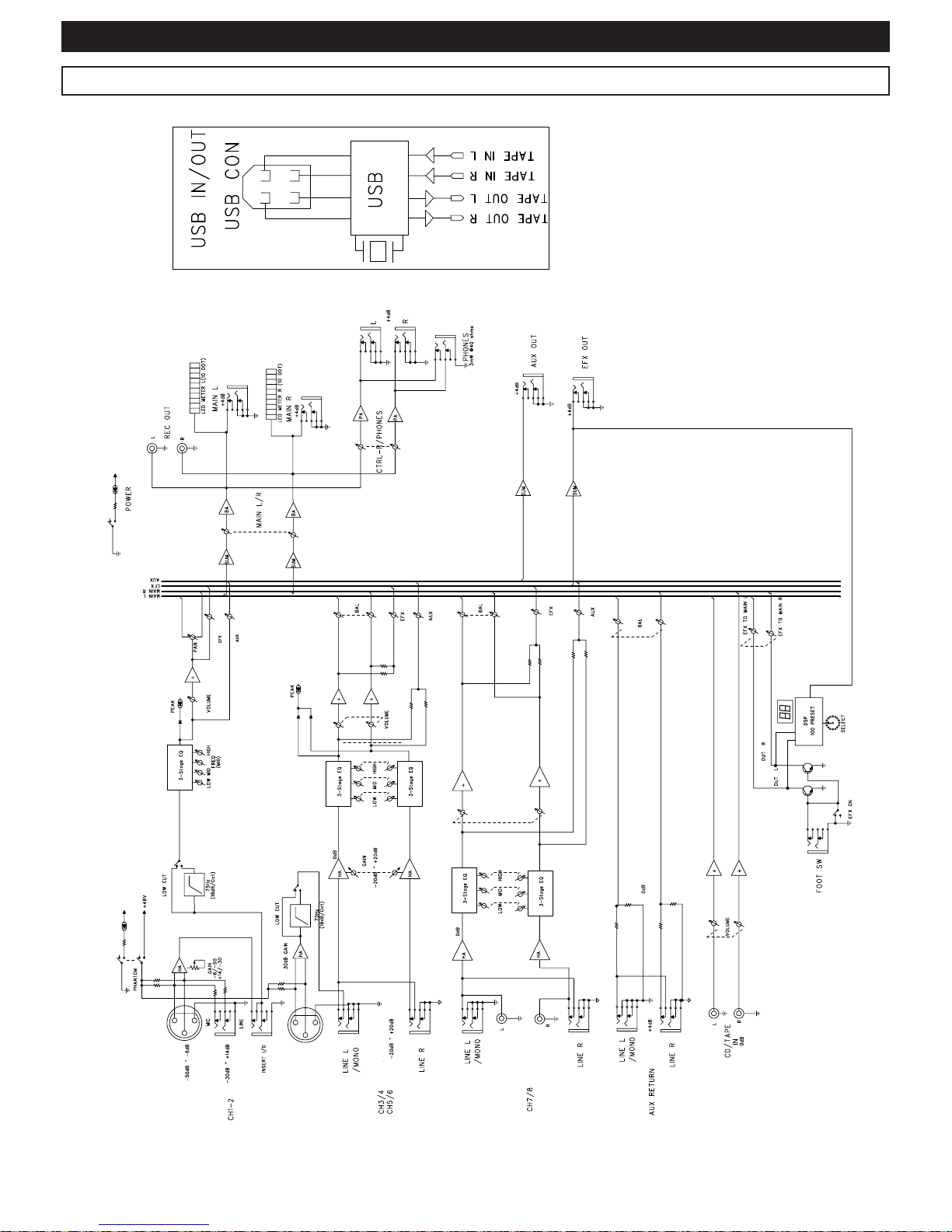
11 - Synoptic
Page 17
MX822 - Live mixer with 4 mics + 5 lines + 24-bit DSP, 10 FX and USB port
Page 17
English
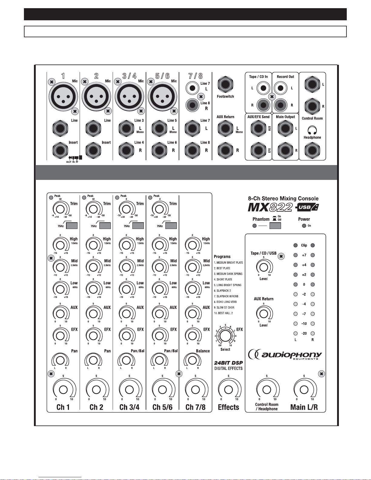
12 - Configuration sheets
Please make several copies of this page and keep them to write down your configurations and settings.
Page 18
MX822 - Live mixer with 4 mics + 5 lines + 24-bit DSP, 10 FX and USB port
Page 18
English
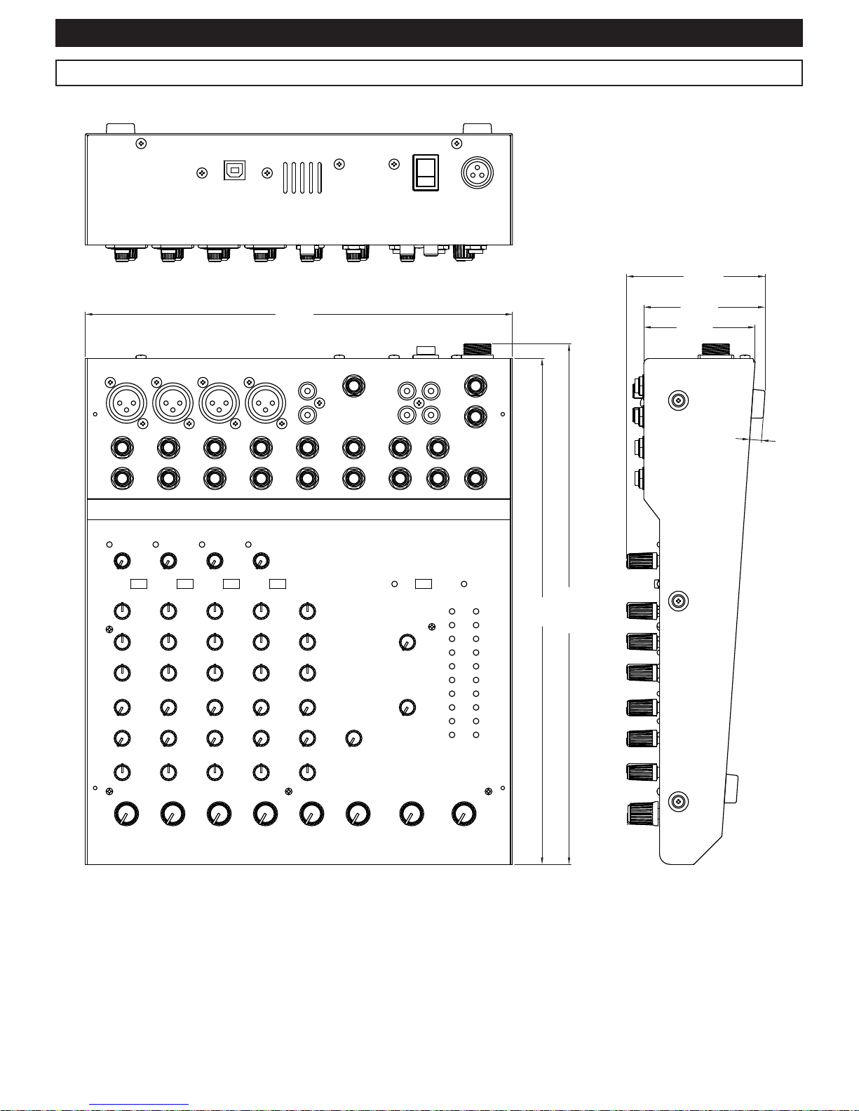
13 - Dimensions
249
295
303,5
64,9
80,6
7
70,6
Page 19

MX822 - Live mixer with 4 mics + 5 lines + 24-bit DSP, 10 FX and USB port
Page 19
English
14 - Notes
Page 20

Because AUDIOPHONY® takes the utmost care in its products to make sure you only get the best possible quality, our products are subjects to modifications without prior notice. That
is why technical specifications and the products physical configuration might differ from the illustrations.
Make sure you get the latest news and updates about the AUDIOPHONY® products on www.audiophony.com
AUDIOPHONY® is a trademark of HITMUSIC S.A. - Zone Cahors sud - 46230 FONTANES - FRANCE
 Loading...