

USER GUIDE
H10901 - Version 1 / 10-2018
COPY
SETUP
BACK
PASTE
IN
1-8
BUS
1-8
SENDS
IN
9-20
SOLO
M
SEL
SOLO
M
SEL
SOLO
M
SEL
SOLO
M
SEL
SOLO
M
SEL
SOLO
M
SEL
SOLO
M
SEL
SOLO
M
SEL
SOLO
M
SEL
Page 2
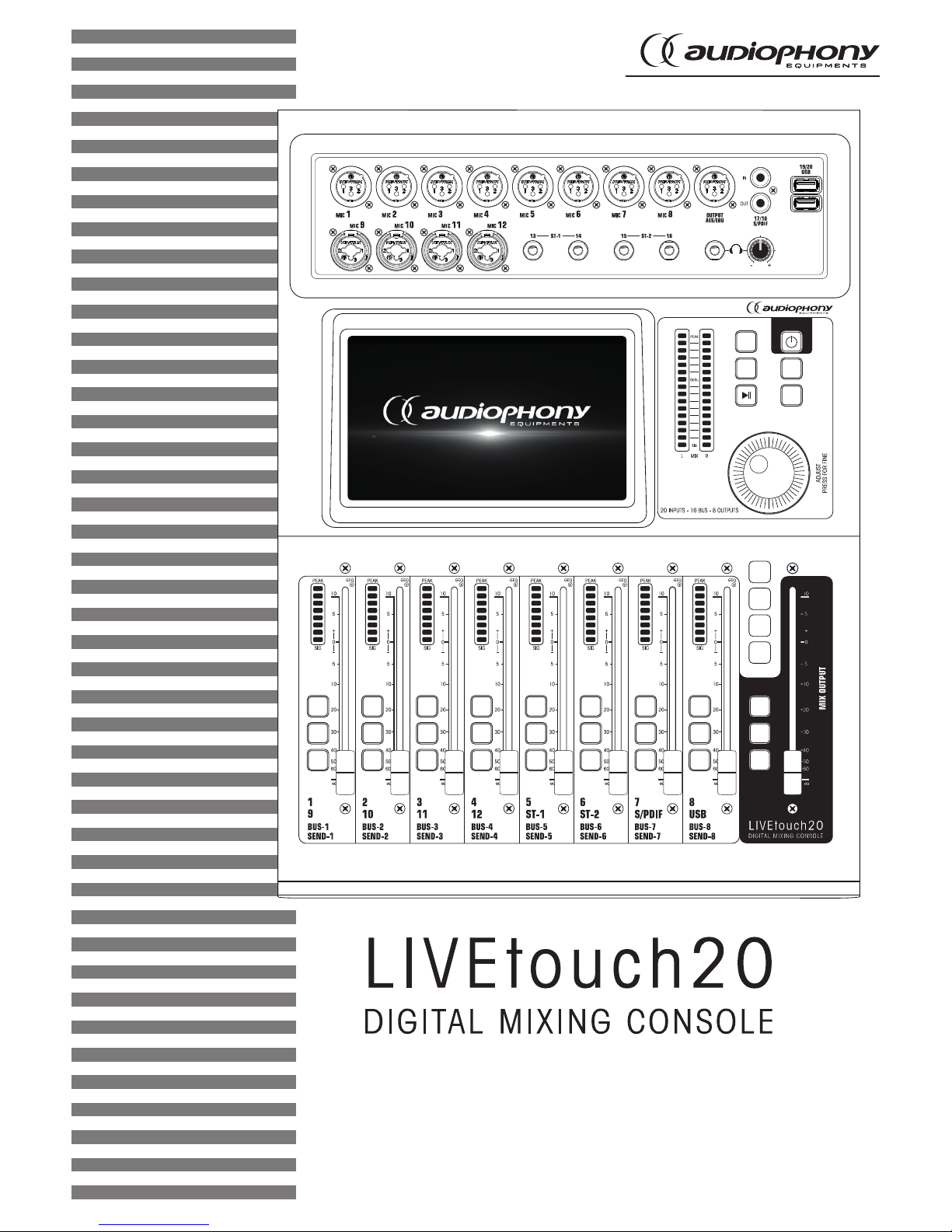
LIVEtouch20 - 20 Channel Digital Mixing Console
English
1 - Please read carefully :
We strongly recommend to read carefully and understand the safety instructions before
attempting to operate this unit.
2 - Please keep this manual :
We strongly recommend to keep this manual with the unit for future reference.
3 - Operate carefully this product :
We strongly recommend to take into consideration every safety instruction.
4 - Follow the instructions:
Please carefully follow each safety instruction to avoid any physical harm or property
damage.
5 - Avoid water and wet locations :
Do not use this product in rain, or near washbasins or other wet locations.
6 - Installation :
We strongly encourage you to only use a fixation system or support recommended
by the manufacturer or supplied with this product. Carefully follow the installation
instructions and use the adequate tools.
Always ensure this unit is firmly fixed to avoid vibration and slipping while operating
as it may result in physical injury.
7 - Ceiling or wall installation :
Please contact your local dealer before attempting any ceiling or wall installation.
8 - Ventilation :
The cooling vents ensure a safe use of this product, and avoid any overheating risk.
Do not obstruct or cover these vents as it may result in overheating and potential
physical injury or product damage. This product should never been operated in a
closed non-ventilated area such as a flight case or a rack, unless cooling vents are
provided for the purpose .
9 - Heat exposure :
Sustained contact or proximity with warm surfaces may cause overheating and product
damages. Please keep this product away from any heat source such as a heaters,
amplifiers, hot plates, etc...
1 - Safety information
This symbol signals an important safety precaution.
The CAUTION symbol signals a risk of product deterioration.
The WARNING symbol signals a risk to the user’s physical integrity.
The product may also be damaged.
Important safety information
Symbols used
Any maintenance procedure must be performed by a CONTEST
authorised technical service. Basic cleaning operations must thoroughly follow our safety instructions.
This product contains non-isolated electrical components. Do not
undertake any maintenance operation when it is switched on as it
may result in electric shock.
This unit is intended for indoor use only. Do not use it in a wet, or
extremely cold/hot locations. Failure to follow these safety instructions could result in fire, electric shock, injury, or damage to this
product or other property.
WARNING : This unit contains no user-serviceable parts. Do not open the
housing or attempt any maintenance by yourself. In the unlikely even your unit may
require service, please contact your nearest dealer.
In order to avoid any electrical malfunction, please do not use any multi-socket, power
cord extension or connecting system without making sure they are
perfectly isolated
and present no defect.
Recycling your device
• As HITMUSIC is really involved in the
environmental cause, we only commercialise
clean, ROHS compliant products.
• When this product reaches its end of life,
take it to a collection point designated by local
authorities. The separate collection and recycling
of your product at the time of disposal will help
conserve natural resources and ensure that it is
recycled in a manner that protects human health
and the environment.
Instructions and recommendations
10 - Electric power supply :
This product can only be operated according to a very specific voltage. These
information are specified on the label located at the rear of the product.
11 - Power cords protection:
Power-supply cords should be routed so that they are not likely to be walked on or
pinched by items placed upon or against them, paying particular attention to cords at
lugs, convenience receptacles and the point where they exit from the fixture.
12 - Cleaning precautions :
Unplug the product before attempting any cleaning operation. This product should be
cleaned only with accessories recommended by the manufacturer. Use a damp cloth
to clean the surface. Do not wash this product.
13 - Long periods of non use :
Disconnect the unit’s main power during long periods of non use.
14 - Liquids or objects penetration :
Do not let any object penetrate this product as it may result in electric shock or fire.
Never spill any liquid on this product as it may infiltrate the electronic components
and result in electric shock or fire.
15 - This product should be serviced when :
Please contact the qualified service personnel if :
- The power cord or the plug has been damaged.
- Objects have fallen or liquid has been spilled into the appliance.
- The appliance has been exposed to rain or water.
- The product does not appear to operate normally.
- The product has been damaged.
16 - Inspection/maintenance :
Please do not attempt any inspection or maintenance by yourself. Refer all servicing
to qualified personnel.
17 - Operating environment :
Ambient temperature and humidity: +5 - +35°C, relative humidity must be less than
85% (when cooling vents are not obstructed).
Do not operate this product in a non-ventilated, very humid or warm place.
Sound levels
Our audio solutions deliver important sound pressure levels
(SPL) that can be harmful to human health when exposed
during long periods. Please do not stay in close proximity
of operating speakers.

Page 3
LIVEtouch20 - 20 Channel Digital Mixing Console
English
2 - General and technical data
Features
12 microphone input + 2 stereo inputs
1 S/PDIF input/output and 1 AES/EBU output
4 mono busses / 5 stereo busses / 1 monitor bus
8 assignable XLR outputs
1 stereo monitor output and 1 headphone output
1 x 7" touch screen
8 effect modules
2 USB plugs for song recording, song playback and scene backups
Technical data
Inputs 12 microphones (4 Combo), 2 stereo, S/PDIF and USB
Input channel functions
Phase, Delay, high pass filter, 4 band parametric equalizer, noise
gate, compressor, pan, effects
Outputs 8 assignable XLR, AES/EBU, S/PDIF and headphone
Internal signal generator White, sinusoidal and white noise
Phantom power 48V independently activatable on each channel
USB Features
Play and record songs, system update, scene backup and external
network card
Screen 7-inch, 1024 x 600 pixel, high definition touchscreen
AD/DA 192 KHz/24 bits max.
Sampling frequency 48 KHz / 44.1 KHz
DSP SHARC ADI 40-bit floating point processor, 4th generation, 450M
Effects
8 modules: 2 Reverbs, 2 Modulation, 2 Delay and 2 x15 bands
graphic equalizers
Système Custom Android
Network Via 1 external USB module (supplied)
Remote control Via 1 iPad application
Power supply 100-240V 50/60Hz > DC12V
Size 445 x 325 x 100 mm
Weight 5.3 Kg
Packaging content
The LIVEtouch20 console
1 external power supply
1 IEC power cord
1 WiFi dongle
The user guide
Page 4
LIVEtouch20 - 20 Channel Digital Mixing Console
English
3 - Overview of the unit
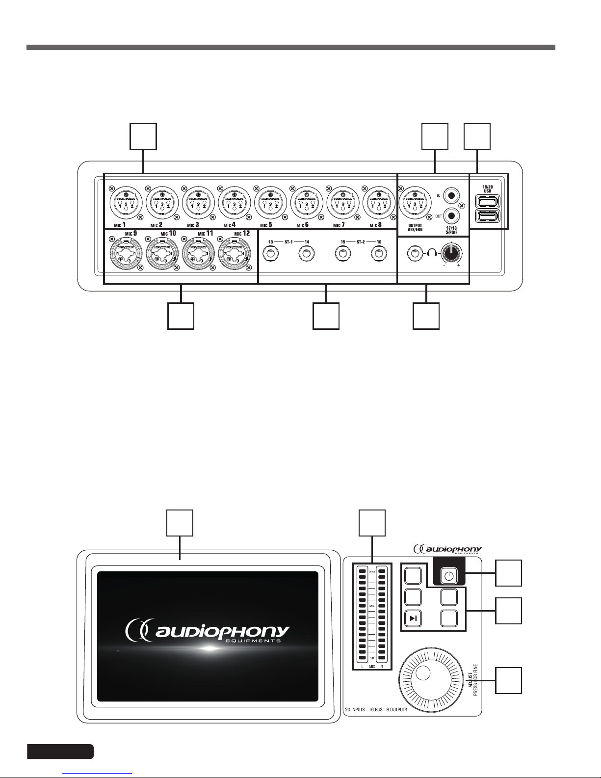
3-1 Front panel connection system
3-2 Main module
1 4
2 3 6
5
1 - 8 XLR mic inputs
2 - 4 combo mic inputs
3 - 2 jack stereo inputs
4 - S/PDIF input/output and AES/EBU output connectors
5 - 2 USB inputs
6 - Pre-listening output with level adjustment
COPY
SETUP
BACK
PASTE
1 2
3
4
5
Page 5
LIVEtouch20 - 20 Channel Digital Mixing Console
English
1 - 7-inch touch screen
2 - 6 bands master vu-meter
3 - 5 control buttons
- SETUP : Provides access to system settings
- BACK : Lets you exit the system menu
- COPY and PASTE : Allows to propagate parameters from one channel to another
- PLAY/PAUSE : Manage USB source playback
4 - POWER button
- Press and hold for more than 3 seconds to turn the console off or on.
- ress this button for 1 second to lock all controls
5 - Adjustment knob
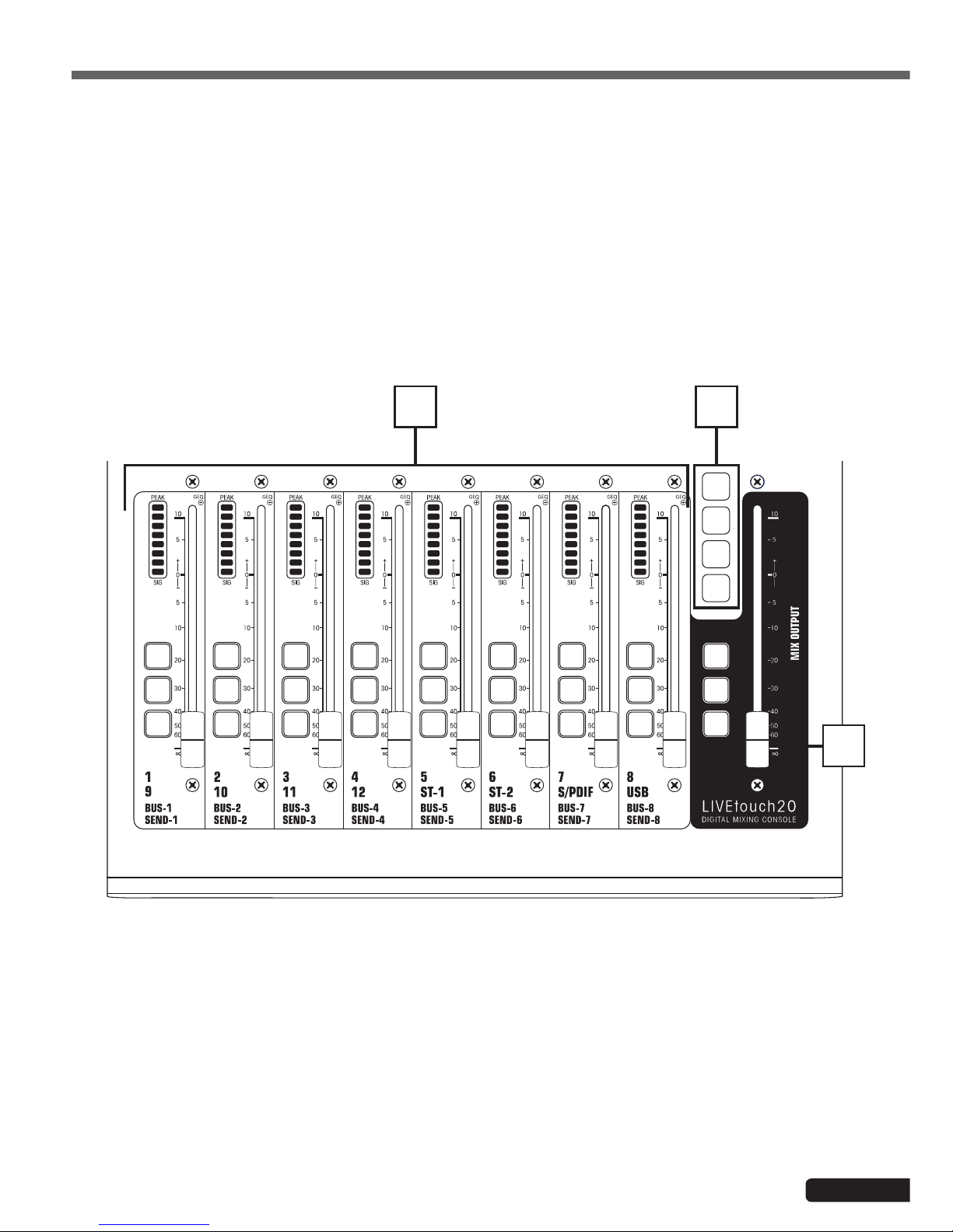
1 - Channels faders
- This section includes the 8-band channel VU meter, SEL (channel selection), SOLO (channel preview), M (channel
mute and bus assignment) and 100mm motorized faders.
2 - Pages selectors
- "IN 1-8" button : Selects mono channels 1 to 8.
- "IN 9-20" button : Selects mono channels 9 to 12, stereo channels 1 and 2, S/PDIF input and USB input
- "BUS 1-8" button : Selects mono outputs 1 to 6 and stereo outputs 7 and 8.
- "SENDS" button: Used to select, for each bus, the channels that will be injected to outputs 1 to 8.
3 - MASTER section
- This section allows you to adjust the level of outputs 7 and 8.
IN
1-8
BUS
1-8
SENDS
IN
9-20
SOLO
M
SEL
SOLO
M
SEL
SOLO
M
SEL
SOLO
M
SEL
SOLO
M
SEL
SOLO
M
SEL
SOLO
M
SEL
SOLO
M
SEL
SOLO
M
SEL
2
3
1
3-3 Faders section
Page 6
LIVEtouch20 - 20 Channel Digital Mixing Console
English
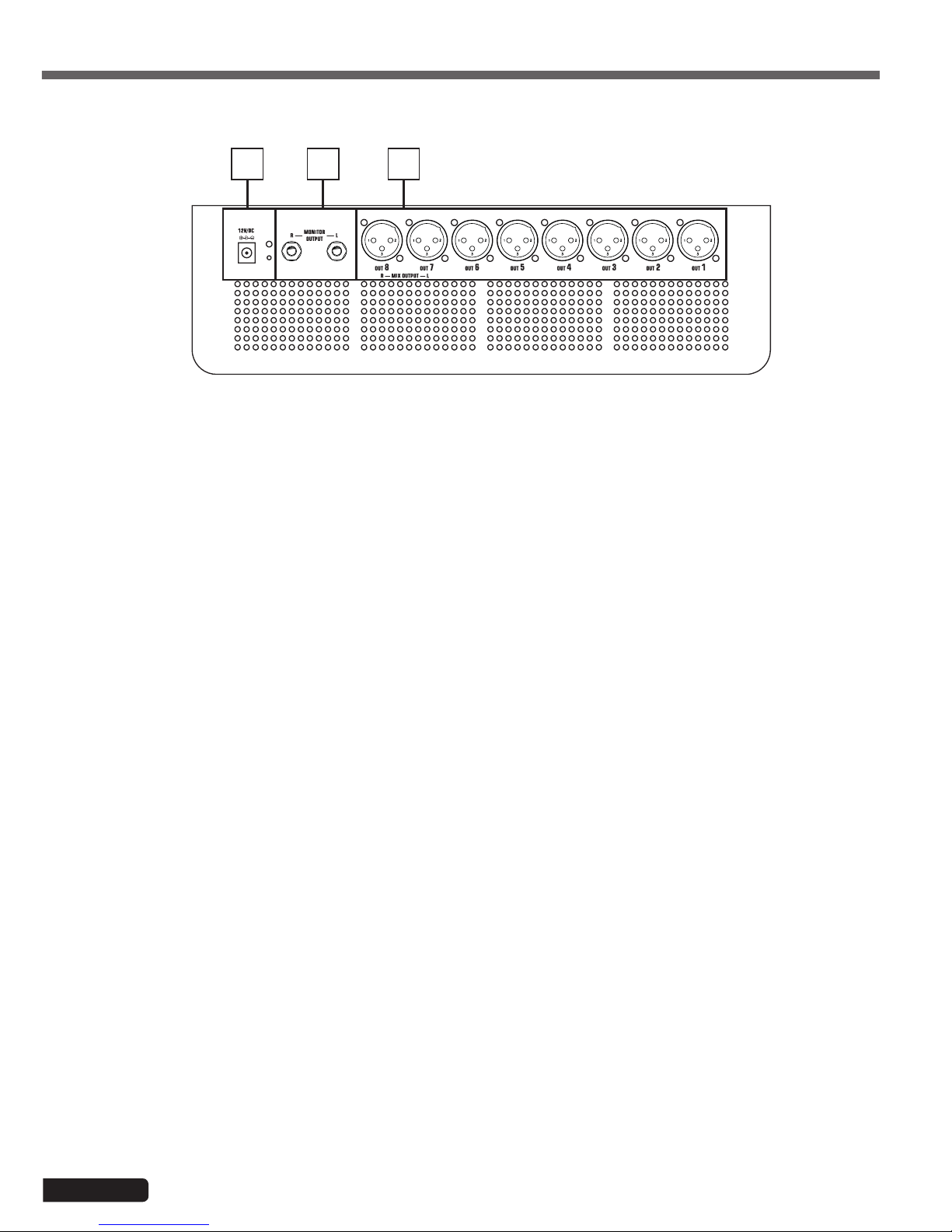
1 - Power supply input : DC12V - 4,17A
2 - Monitor output
- 6.35 Jack stereo output.
3 - 1 to 8 outputs
- Balanced outputs on XLR plugs.
3-4 Rear pannel
321
Page 7
LIVEtouch20 - 20 Channel Digital Mixing Console
English
4-1 Inputs channels
4-1-1 Mic inputs
4 - Advanced Features
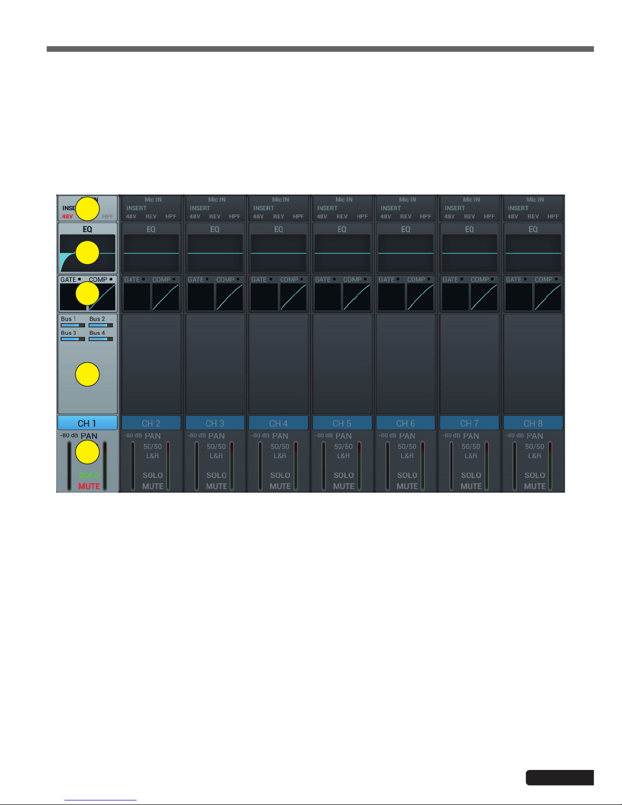
LIVEtouch20 console features 12 mono inputs, 2 analog stereo channels, 1 S/PDIF input and 1 USB input.
A MIC input channel contains five individual modules: Input stage, Equalizer, Dynamic, Send to bus and Output stage. A
simple click on a module will bring up a subpage with other options. Subpages can be closed with the red "close" button
in the upper right cornerB.
1
2
3
4
5
1 - Input Stage
Indicates the status of 48V phantom power, phase, delay, high pass filter and effects.
2 - EQ
Displays the current equalization and allows access to the settings.
3 - Dynamics
Displays compressor and noise gate status and provides access to settings.
4 - Busses sends
Displays the buses to which the slice is sent and allows access to the bus selection.
5 - Output
Displays channel name, pan setting, preview (SOLO), MUTE and channel level .
Page 8
LIVEtouch20 - 20 Channel Digital Mixing Console
English
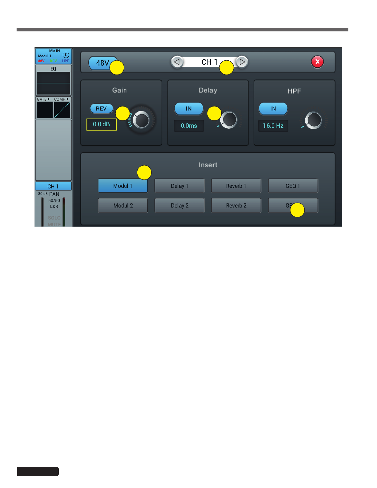
1 - Alimentation fantôme 48V
Active ou désactive l'alimentation fantôme sur le canal en cours.
2 - Channels selector
Allows you to switch from one channel to another while remaining on the same page.
3 - Rev
Enables phase reversal. By default phase reversal is inactive.
4 - Delay
Enables Delay, by default Delay is disabled. The time can be set either via the setting wheel or directly on the
display. For fine adjustment, hold down the knob.
The time range is from 0 ms to 200 ms.
5 - HPF
Enable the high pass filter, by default the high pass filter is disabled. The frequency can be set either via the setting wheel or directly on the display. For fine adjustment, hold down the knob.
Frequency is adjustable from 16 Hz to 400 Hz, default is 16 Hz.
6 - Insert
Press one of the buttons on the effect module to insert it before equalizing the channels. Each effect module can
only be inserted in one place and the input channels allow only one effect module to be used. When a selected
module is used in another channel or bus, a pop-up window appears: "The module can only be used once and is
already used by xxx. Do you want to use the force module now? Yes / No".
To change the effect settings, press the SETUP button, then press FX and click a module to open a dialog box for
the effect.
4-1-2 Subpage of the mono channel input stage
1 2
3
4
5
6
Page 9
LIVEtouch20 - 20 Channel Digital Mixing Console
English
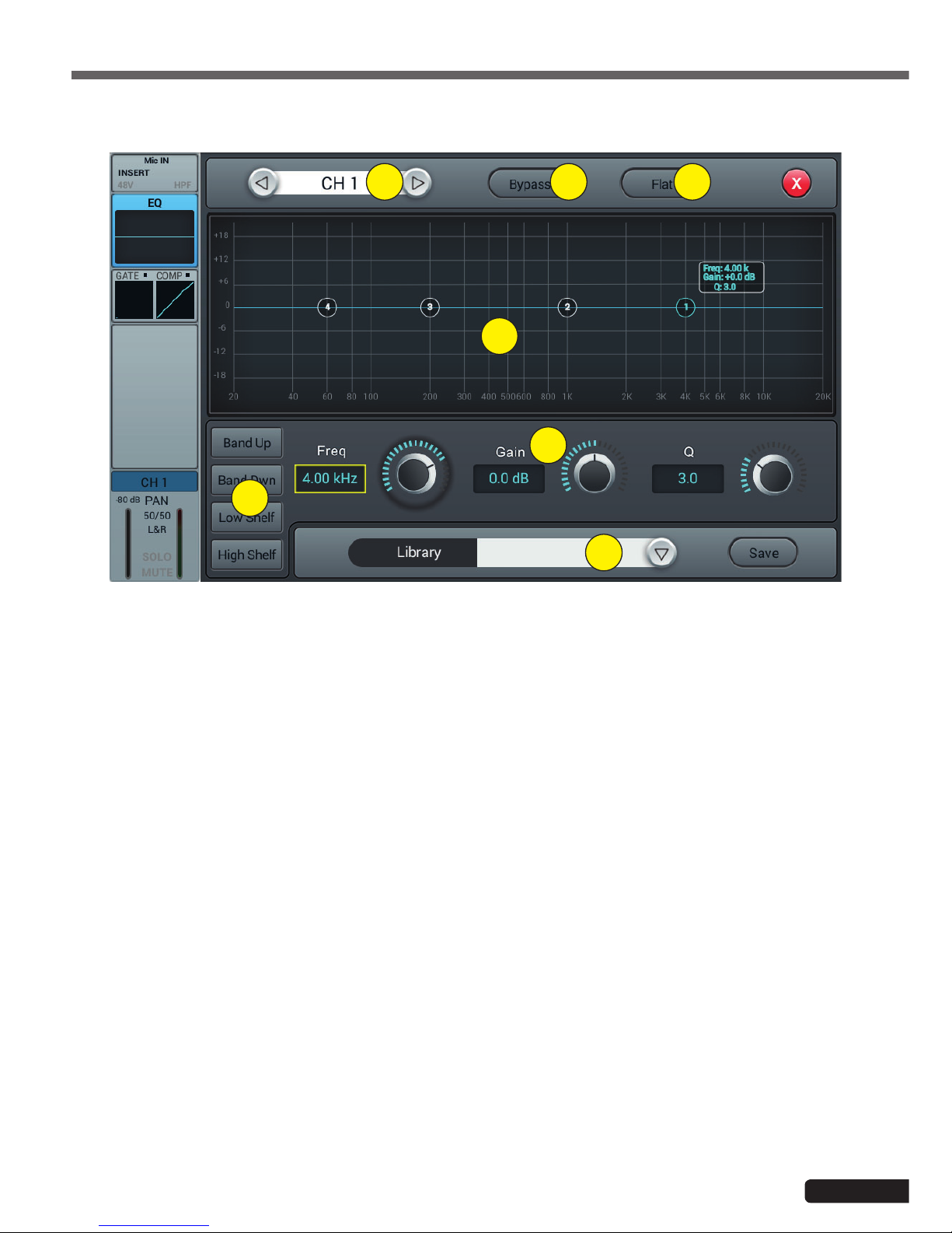
1 - Channels selector
Allows you to switch from one channel to another while remaining on the same page.
2 - Bypass
Enables or disables the equalizer on the current channel. By default the equalizer is active.
3 - Flat
Allows the equalizer to be flat again. This action is irreversible, the settings will be lost.
4 - 4-band EQ graph
The four points on the curve indicate the position of each parametric equalizer. You can select each point to adjust
the equalization. When a point is selected you can also adjust its equalization via insert 6 (frequency, gain and
Q-band width).
5 - Curve point selection keys
Use these keys to move from one point to another.
6 - Réglages de chaque point
These three potentiometers allow the adjustment of the points via the main encoder:
-Gain : Adjustable from -18dB to +18dB.
-Frequency : Each band can be set to a value between 20 Hz and 20 kHz. The default values are : HF 4kHz, HMF
1kHz, LMF 200 Hz, LF 60Hz. The terms HF, HMF, LMF and LF refer only to the initial band setting; there are no
restrictions in the equalizer band setting, so that after the setting, LF may actually be at the top of the frequency
range.
-Q : allows you to adjust the bandwidth from 0.5 (wide) to 10.0 (narrow). The default value is 0.5.
7 - Library
The library allows you to save and load the user's EQ settings. Click the drop-down menu and select a library
entry from the list to load its settings. Click the "Save" button and select the desired library location (1 - 16) from
the list to save the current equalizer settings. A virtual keyboard will appear on the screen to enter a name for the
setting. Finally, click "confirm" to save the setting or "cancel" to cancel.
4-1-3 Parametric equalizer sub-page
1 3
4
6
7
5
2
Page 10
LIVEtouch20 - 20 Channel Digital Mixing Console
English
1 - Channels selector
Allows you to switch from one channel to another while remaining on the same page.
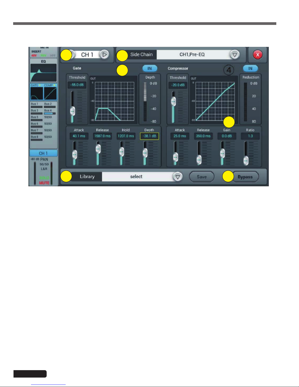
2 - Side chain
This function allows you to use the signal from another channel to control the compression of the selected
channel. This can be useful when channel groups are used for a single instrument (for example, drums) to ensure
consistency of compression of all channels within the group. Click the drop-down button and select the channel
to use as the "Side chain" to control the active channel. The selection also allows you to switch between Pre and
Post equalization modes.
3 - Gate
IN : Enables the Gate to be activated. It is inactive by default.
Curve : The curve is divided into 3 parts - Attack (left), Hold (middle) and Release (right).
The threshold is indicated on the Y axis while the X axis indicates the relative time for each section.
Settings parameters : The curve is divided into 3 parts - Attack (left), Hold (middle) and Release (right).
The threshold is indicated on the Y axis while the X axis indicates the relative time for each section.
Threshold : The threshold varies from -80 dB to 0 dB with default -80dB. Any signal below the threshold will be
muted, so that the signal level must exceed the threshold to pass the noise gate.
Hold : (hold time) : From 2 ms to 2000 ms with default 2 ms.
Attack : (attack time) : Range 0.5 ms to 100 ms, default 3 ms.
Release : (temps de relâchement) : peut être ajusté de 2 ms à 2000 ms, par défaut 350 ms, ce qui est compatible
avec la plupart des sources sonores.
Depth : (release time) : can be adjusted from 2 ms to 2000 ms, default 350 ms, which is compatible with most
sound sources.
4-1-4 Dynamics sub-page
1
5
3
4
6
2

Page 11
LIVEtouch20 - 20 Channel Digital Mixing Console
English
4 - Compressor
IN : Activates the compressor. It is inactive by default.
Courbe : The curve shows the gain relationship between the input and output signals. The curve is divided into
two parts - below and above the threshold value.
While any signal below Threshold will pass the compressor virtually unchanged, Ratio is applied to signals exceeding the Threshold value. Therefore, these signals are attenuated (for a ratio other than 1:1), by observing the
Attack and Release settings. The gain allows the "Make-up" gain to reduce the output volume of the signal after
compression.
Parameter adjustment : Adjust the compressor by sliding the slider, or by using the knob on the control panel
(fine adjustment can be activated by holding the knob down).
Threshold : Changes the compressor threshold in the range -80 dB to 0 dB. The default value is -20 dB. Any
signal below the threshold will not be compressed. Signals above the Threshold are compressed by applying the
Ratio and observing the attack and release time settings.
Ratio : (compression ratio) : can be set between 1.0 and 20.0, default is 1.0
Attack : (attack time) : Range 0.5 ms to 100 ms, default 25 ms.
Release : (release time) : Adjustable from 20 ms to 5 s, the default value is 350 ms, i.e. compatible with most
sound sources.
Gain : To compensate the compression, the range is -12 dB to +12 dB, the default value is 0 dB.
5 - Library
The library allows the user's dynamic settings to be saved and loaded. Click the drop-down menu and select a
library entry from the list to load its settings. Click the "Save" button and select the desired library location (1 - 16)
from the list to save the current dynamic settings. A virtual keyboard will appear on the screen to enter a name for
the current setting. Finally, click "confirm" to save the setting or "cancel" to cancel.
6 - Bypass
Deactivates dynamic settings
Page 12
LIVEtouch20 - 20 Channel Digital Mixing Console
English
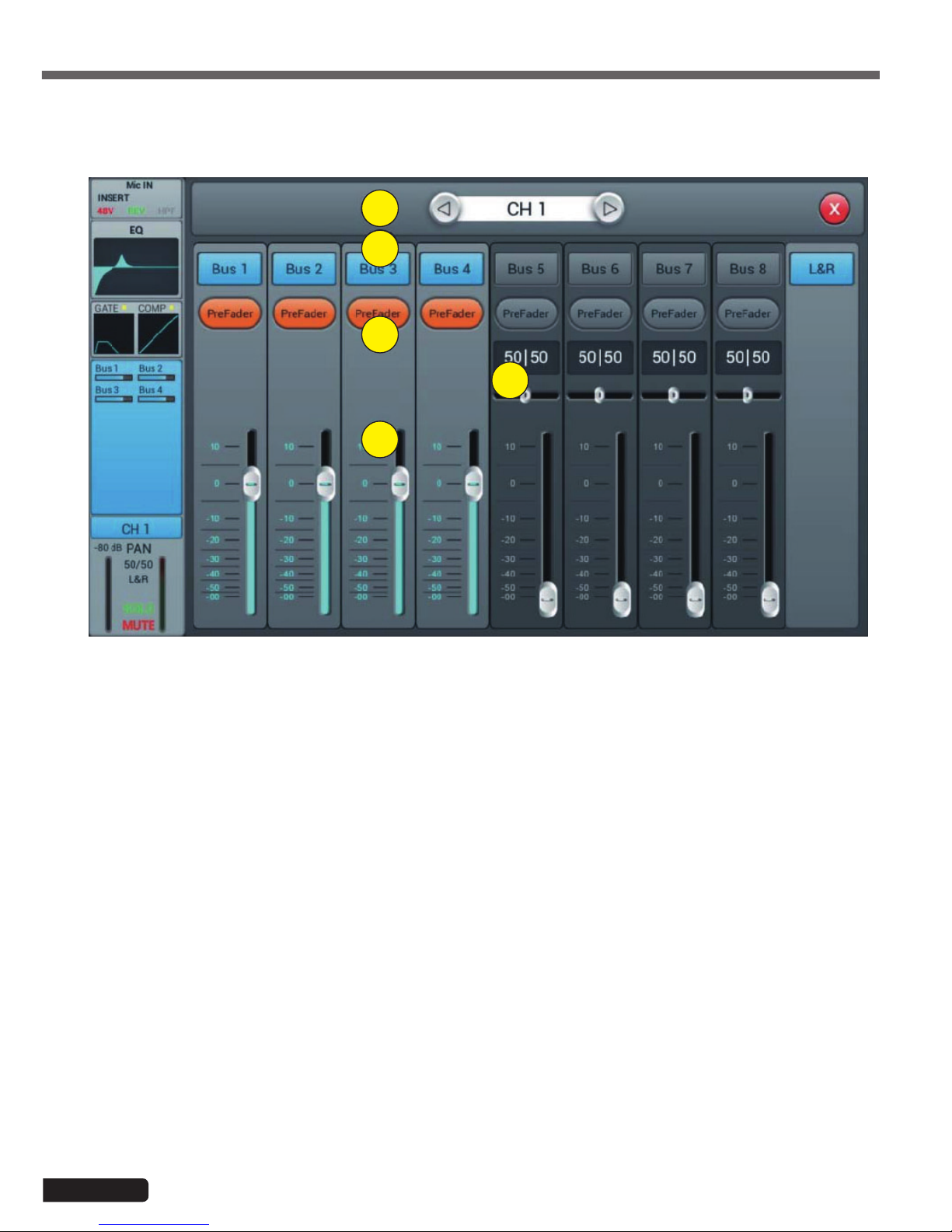
4-1-5 Bus Send sub-page
1
2
3
5
4
1 - Channels selector
Allows you to switch from one channel to another while remaining on the same page.
2 - Activate sending to buses
Press a bus button to send the active channel to it, press again to disable sending.
3 - Pre/PostFader
Switching between pre- and post-fader sent to a bus. The pre-fader does not include the gain value of the fader,
which can be useful for effect sends or monitoring. The default value is pre-fader.
4 - Pan
Controls panning in a stereo bus. The default value is 50|50 (middle). The PAN value can be changed by dragging
the slider or turning the adjustment dial. Press the numeric parameter control twice to return to the default value.
5 - Sending level to buses
Controls the level at which the signal is sent to the selected bus. This can be changed by moving the cursor on
the screen or by using the physical fader.
Each input channel can send signals to 4 mono buses (1-4), 2 stereo buses (5-8 including L/R master).

Page 13
LIVEtouch20 - 20 Channel Digital Mixing Console
English
4-1-6 Output stage sub-page
1
2
3
5 6
4
1 - Channels selector
Allows you to switch from one channel to another while remaining on the same page.
2 - Panoramique
Controls the panning of the Master output. The default value is 50|50 (middle). The PAN value can be changed by
the encoder on the screen or by turning the control dial. Press the numerical control of the setting twice to reset
the setting to its default value.
3 - Solo
This is a copy of the SOLO hardware button on the front panel. Press to enable or disable the signal sent to the
solo monitor bus.
4 - Mute
Like Solo, it is a copy of the M button on the front panel. Press to mute or not the channel, which will mute or
mute all pre- and post-fader sends from the active channel to all buses, including the L/R Master.
5 - Fader
This is a copy of the physical fader of the selected channel. You can change the fader on the screen and the
physical fader will follow accordingly. Press the numerical control of the setting twice to reset the setting to its
default value.
6 - Vu-meter
This displays the pre-fader level of the signal, so regardless of the fader setting, the signal will be displayed here if
it is present.
Here you can set the pan and level of the Master as well as the Solo / Mute.

Page 14
LIVEtouch20 - 20 Channel Digital Mixing Console
English
4-1-7 Stereo inputs
Like the MIC channels, the two stereo inputs also include five modules: Input, equalizer, dynamic, bus sending and output.
A simple click on a module will bring up a subpage with other options. The subpages can be closed with the red "close"
button in the upper right corner.
1
2
3
4
5
1 - Input stage
Indicates the status of the phase, delay, high pass filter and effects.
2 - EQ
Displays the current equalization and allows access to the settings.
3 - Dynamics
isplays compressor and gate status and provides access to settings.
4 - Buses sends
Displays the buses to which the channel is sent and provides access to the bus selection.
5 - Output stage
Displays channel name, pan setting, preview (SOLO), MUTE and channel level.

Page 15
LIVEtouch20 - 20 Channel Digital Mixing Console
English
1
2
3
4 5
6
1 - Channels selector
Allows you to switch from one channel to another while remaining on the same page.
2 - SUM
Sum the left and right inputs, so that both sides of the stereo channel will contain the same signal (mono). This
can also be used to copy the signal to both channels if only one side of the stereo signal is connected.
3 - REV
The phase reverses the left side of your stereo signal. In combination with SUM, this can be useful to cancel the
stereo medium, which usually contains the voice of a recording, and create a simple karaoke effect.
4 - Trim
Allows digital amplification or attenuation of the input signal. Press IN to activate, the default value is disabled.
Adjust the trim on the touch screen or use the adjustment dial (fine adjustment can be activated by pressing and
holding the dial). Gain can be adjusted from -20 dB to 20 dB with 0dB as default.
5 - HPF
Enable the high pass filter, by default the high pass filter is disabled. The frequency can be set either via the setting wheel or directly on the display. For fine adjustment, hold down the knob.
The frequency is adjustable from 16 Hz to 400 Hz, the default value is 16 Hz.
6 - Insert
Press one of the buttons on the effect module to insert it before equalizing the channels. Each effect module can
only be inserted in one place and the input channels allow only one effect module to be used. When a selected
module is used in another channel or bus, a pop-up window appears: "The module can only be used once and is
already used by xxx. Do you want to use the force module now? Yes / No".
To change the effect settings, press the SETUP button, then press FX and click a module to open a dialog box for
the effect.
4-1-8 Stereo inputs sub-page

Page 16
LIVEtouch20 - 20 Channel Digital Mixing Console
English
4-1-9 Parametric equalizer sub-page
This page is the same as for MIC channels. All settings will be applied to both channels of the stereo signal.
For ST1 and ST2, this page is the same as for MIC channels, with all settings applied to both channels of the stereo signal.
For S/PDIF and USB channels, there is no dynamic section.
For ST1 and ST2, this page is the same as for the MIC channel. For S/PDIF and USB Sending channels is limited to 5-8
stereo and Master LR buses. For mono buses, the sum on both sides of the stereo channel is actually sent to the bus. For
stereo and Master LR buses, a scale replaces the Panning : the center (50|50) of the BAL will send the left and right parts
of the stereo channel to the corresponding left and right parts of the Bus. Any other setting will attenuate one side of the
stereo channel, for example (100|0) only sends the left side of the stereo channel to the left side of the bus, the right side
being muted.
4-1-10 Dynamics sub-page
4-1-11 Bus Send sub-page

Page 17
LIVEtouch20 - 20 Channel Digital Mixing Console
English
LIVEtouch20 allows mixing in a total of 8 output buses - 4 Mono (Bus 1~4), 2 Stereo (Bus 5~8 including Master L/R). In
fact, there is another stereo bus for monitoring via SOLO, which can be switched to pre or post-fader listen (PFL/AFL).
Press the BUS1-8 button on the front panel or drag to the right of the stereo channels on the screen to switch to BUS 1-8
view or by pressing the SEL button on the Master L/R to display Master view:
The left side of the page gives a complete overview of all the inputs and outputs of the console, the right side shows the
Master L/R output band, whose functionality exactly follows the 7-8 stereo buses.
Each output bus contains 4 modules - input stage, EQ, input source and output stage. With the exception of the input
source, which is in view only, all other modules will display a subpage if the corresponding part of the screen is clicked.
The subpages can be closed with the red "close" button in the upper right corner.
1
2
3
4
4-2 Output busses

Page 18
LIVEtouch20 - 20 Channel Digital Mixing Console
English
1 - Input stage
Displays the physical output assigned to each bus as well as the status of the effect inserts.
2 - EQ
Displays a parametric equalizer graph representing the equalizer settings.
3 - Input source
Displays the status and send level of each channel as a bar graph. For clarity, only channels whose sending to a
given bus is enabled are displayed here.
4 - Output stage
Displays name, Pan/BAL value, Solo, Mute, delay, fader and level information. Double-click, for example Bus 1, to
change the name of the selected channel using a virtual keyboard that will appear on the screen.
Buses 1 to 4 are mono busses
4-2-1 Input stage sub-page
For mono buses 1-4, this page allows you to configure the send level, pan and type (Pre-/Post-Fader) for stereo buses
5-8. Since stereo buses cannot send to themselves, these buses (as well as mono buses) only enable/disable sending to
the Master L/R.
The bus text label indicates the physical output plug to which it is assigned. For example, OUT 1 is plug 1 on the back of
the console, etc. The assignment can be configured in the SETUP menu and then PATCH.
1
2
3
4
5
6
1 - Channels selector
Allows you to switch from one channel to another while remaining on the same page.
2 - Activate sending to busses
Press a bus button once, to send a channel signal to the bus, press again to turn it off.
3 - Pre/Post Fader
Switching between pre- and post-fader sent to a bus. The pre-fader does not include the gain value of the fader,
which can be useful for effect sends or monitoring. The default value is pre-fader.

Page 19
LIVEtouch20 - 20 Channel Digital Mixing Console
English
1
2
3
4 5
6 7
4 - Pan
Controls the panoramic of the bus. The default value is 50|50 (middle). The PAN value can be changed by the
encoder on the screen or by turning the control dial. Press the numerical control of the setting twice to reset the
setting to its default value.
5 - Send level
Controls the level at which the signal is sent to the selected bus. This can be changed by moving the cursor on
the screen.
6 - Insert
Press a button on the effect module to insert it before the bus equalizers. Each effects module can be inserted
at a single point and while the input channels allow only one effects module to be inserted, all buses allow the
subsequent insertion of two effects modules. The order of the modules is determined by the selection order. When
a selected module is used in another channel or bus, a pop-up window appears: "The module can only be used
once and is already used by xxx. Do you want to use the force module now? Yes / No".
To change the effect settings, press the SETUP button, then press FX and click a module to open a dialog box for
the effect.
4-2-2 Parametric equalizer sub-page
4-2-2 Output stage sub-page
This page is the same as for MIC channels.
This page contains Delay, PAN, Solo, Mute, Fader Level Control and Signal Level Display. Bus5 to Bus8 and L&R bus
outputs are similar to Bus1 to Bus4.
1 - Channels selector
Allows you to switch from one channel to another while remaining on the same page.
2 - Delay
Enables Delay, by default Delay is disabled. The time can be set either via the setting wheel or directly on the
display. For fine adjustment, hold down the knob.
The time range is 0 ms to 200 ms.

Page 20
LIVEtouch20 - 20 Channel Digital Mixing Console
English
3 - Pan
Controls the panning of the Master output. The default value is 50|50 (middle). The PAN value can be changed by
the encoder on the screen or by turning the control dial. Press the numerical control of the setting twice to reset
the setting to its default value.
3 - Solo
Press to enable or disable the signal sent to the solo monitor bus.
4 - Mute
Press to mute or unmute the channel.
5 - Fader
This is a copy of the physical fader of the selected channel. You can change the fader on the screen and the
physical fader will follow accordingly. Press the numerical control of the setting twice to reset the setting to its
default value.
6 - Vu-meter
Channel signal level indicator, indicates the post-fader signal level.

Page 21
LIVEtouch20 - 20 Channel Digital Mixing Console
English
5 - Setup
1
2
3
4
5
6
1 - Information
System Version shows the version of APK, DSP, Fader and other software on this console. The IP address indicates the console's IP address.
2 - Sample Rate
The default setting is 48.0 KHz. When you press 44.1 KHz once, a window opens: "The 44.1 KHz sample rate is
only used for digital outputs", then the 44.1 KHz zone turns on and the 48 KHz zone turns off. The default value is
always 48.0 KHz after rebooting the system.
3 - Delay Unit
Selects the unit of measurement for the Delay.
4 - System
- Maintenance: Allows access to the operating system.
- SetupWifi : Allows you to set the Wifi access to the console.
5 - Brightness
Adjusts the brightness of the touch screen.
6 - Crossover
Press BUS 8 IN, the filter works. At this point, the BUS8 operates in low mode. The control knob can be used to
change the cutoff frequency from 40Hz to 300Hz. The filter slope is 24dB/oct.
Press the Master L/R IN button, the filter works. Master L/R output operates in low cut mode. The slope of the
filter is 24dB/oct. The cut-off frequency adjustment range is 40Hz to 300Hz. Using these two filters reasonably
results in a 2.1.
5-1 Setup page

Page 22
LIVEtouch20 - 20 Channel Digital Mixing Console
English
5-1-1 Maintenance sub-page
1 5
2 6
3 7
4 9
1 - Update from USB
By pressing the "Update from USB" button, a dialog box opens "After the update, the system restarts automatically. If you are sure you want to update the system, press "Install" and complete the installation by following the
information.
2 - Factory Reset
By pressing the "Factory Reset" button once, a "Do you wont to do a Factory Reset? This resets your settings to
the factory default values. Press "Factory Reset" and the console will restart automatically.
If the console seems to slow down after a long period of use, you can use this function to return to factory settings. However, please back up all your important data by exporting it to USB before the session begins. Resetting
the consol will irrevocably erase all internal data.
3 - Toggle Dev Mode
Debug mode, not recommended for non-professional users.
4 - Android Home Screen
Debug mode, not recommended for non-professional users.
5 - Import Settings
Mode débogage, déconseillé aux utilisateurs non professionnels.
6 - Export Settings
Debug mode, not recommended for non-professional users.
7 - Time Settings
Setting the system time.
8 - Save log
Debug mode, not recommended for non-professional users.
CAUTION
If a malfunction of the console was due to a bad handling of
the functionalities reserved to the professionals, the guarantee
would be cancelled.

Page 23
LIVEtouch20 - 20 Channel Digital Mixing Console
English
1
2
1 - Default
In default mode, Bus1-Bus 5R are assigned to OUT 1 ~ OUT 6, Master L and Master R are assigned to OUT 7-8,
S/PDIF OUT and USB OUT.
2 - Custom
Switch to custom mode after clicking one of the Custom 1, 2 or 3 buttons. Click one of the menus on any output,
then select the bus to assign.
Note: The S/PDIF and USB outputs can only select stereo bus pairs or master output bus pairs, the 8 analog
outputs can select one of the 8 buses.
After the system reboot, the Patch setting is always the one you set before you last turned off the console.
This page is mainly used to select the buses to assign to the 8 analog outputs, S/PDIF output and USB output.
The console has 4 mono busses (Bus 1~Bus 4), 2 stereo busses (Bus 5L~Bus 8R including1 Master L, Master R output
bus).
5-2 Patch page

Page 24
LIVEtouch20 - 20 Channel Digital Mixing Console
English
5-3 Meter page
5-4 FX page
The page contains two parts: the input signal level and the outputs.
The signal level of the input channels has three modes IN, Pre Fader and Post Fader with Pre Fader by default. To select
the signal mode to display, click the corresponding button.
The output signal level has two modes Pre Fader and Post Fader with Pre Fader by default. To select the signal mode to
display, click the corresponding button.
On the right side of the output levels, you can see the names of the buses that are assigned to the ports.
1
2

Page 25
LIVEtouch20 - 20 Channel Digital Mixing Console
English
Click the "Modulation1 or 2" button in the FX subpage to access the modulation parameter subpage below.
1 2
3
4 5
6
The effects consist of 8 modules, which are: 2 Modulations, 2 Delay, 2 Reverb and 2 15-band graphic equalizers.
Each module can only be inserted once into an input processing channel or bus processing channel. You can
insert up to two effects into a bus or channel. For example reverb & delay to create a vocal effect.
1 - The modules
Click on the effects module to open a subpage setting this module.
Click the close button (red X) on the subpage to exit and return to the FX page.
2 - Busses selection
Click on the drop-down menu, and select a bus (Bus1~Bus8, Master L/R).
If the selected bus has selected an FX module in the input part of the channel, the left frame displays the selected
FX modules in the selection order from left to right.
If nothing has been selected, you can drag the FX module over the empty image (if the FX module was occupied
by another channel or bus option, a dialog box opens "The module can only be used once and is already used by
xxx. Are you sure you want to use the module? force now? Yes No").
5-3-1 Modulation sub-page
1 - Modules selection
Use the left and right arrows to select the module to be set.
2 - Type
Click the drop-down menu, then choose a modulation type from the list: Slow Chorus/Fast Chorus/Slow Flanger/
Fast Flanger, Fast Celeste/Slow/Celeste, Fast Rotor/Slow Rotor.
3 - Dry/Wet
Adjust the Dry-Wet setting by sliding the slider or turning the knob on the control panel.

Page 26
LIVEtouch20 - 20 Channel Digital Mixing Console
English
4 - EQ LS
Curve : Displays the LS curve
Gain : ±18 dB, with a default value of 0 dB. Adjust the gain by turning the knob or on the touch screen (fine
adjustment can be activated by holding the knob down). Press the parameter frame twice to return to the default
value.
Freq : Varies from 20 Hz to 200 Hz, with a default setting of 100 Hz. Adjust the frequency by turning the knob
or on the touch screen (fine adjustment can be activated by holding the knob down). Press the parameter frame
twice to return to the default value.
5 - EQ HS
Curve : Displays the HS curve
Gain : ±18 dB, with a default value of 0 dB. Adjust the gain by turning the knob or on the touch screen (fine
adjustment can be activated by holding the knob down). Press the parameter frame twice to return to the default
value.
Freq : Varies from 1.5 KHz to 15 KHz, with a default setting of 6.3 KHz. Adjust the frequency by turning the knob
or on the touch screen (fine adjustment can be activated by holding the knob down). Press the parameter frame
twice to return to the default value.
6 - Other parameters
Speed : Varies from 50 to 200, with a default setting of 100. set the speed by turning the knob or on the touch
screen (fine adjustment can be activated by holding down the knob). Press the parameter frame twice to return to
the default value.
Intensity : Varies from 50 to 200, with a default setting of 100, adjust the intensity by turning the knob or on the
touch panel (fine adjustment can be activated by holding down the knob).
Pre-Delay : Set the Pre Delay time, from 0 to 100ms, with a default setting of 0. set the Pre Delay time by turning
the dial or on the touch screen (fine adjustment can be activated by holding down the dial).
5-3-2 Delay sub-page
Click the "Delay or 2" button in the FX subpage to access the Delay settings subpage below.
1 2
3
4 5
6

Page 27
LIVEtouch20 - 20 Channel Digital Mixing Console
English
1 - Modules selection
Use the left and right arrows to select the module to be set.
2 - Type
Click the drop-down menu, then choose a modulation type from the list: One Echo 1/4, Two Echo 1/8, Three Echo
1/16, Three Echo 1/16, Delayed Four Echo 1/16, One Echo 1/4 with 4 Reflect.
3 - Dry/Wet
Adjust the Dry-Wet setting by sliding the slider or turning the knob on the control panel.
4 - EQ LS
Curve : Displays the LS curve
Gain : ±18 dB, with a default value of 0 dB. Adjust the gain by turning the knob or on the touch screen (fine
adjustment can be activated by holding the knob down). Press the parameter frame twice to return to the default
value.
Freq : Varies from 20 Hz to 200 Hz, with a default setting of 100 Hz. Adjust the frequency by turning the knob
or on the touch screen (fine adjustment can be activated by holding the knob down). Press the parameter frame
twice to return to the default value.
5 - EQ HS
Curve : Displays the HS curve
Gain : ±18 dB, with a default value of 0 dB. Adjust the gain by turning the knob or on the touch screen (fine
adjustment can be activated by holding the knob down). Press the parameter frame twice to return to the default
value.
Freq : Varies from 1.5 KHz to 15 KHz, with a default setting of 6.3 KHz. Adjust the frequency by turning the knob
or on the touch screen (fine adjustment can be activated by holding the knob down). Press the parameter frame
twice to return to the default value.
6 - Others parameters
Factor : Varies from 0 to 13, with a default setting of 1. set the Factor by turning the knob or on the touch panel
(fine adjustment can be activated by holding down the knob).
Tempo : Varies from 40 to 240 BPM, with a default setting of 80. Adjust the intensity by turning the knob or on the
touch screen (fine adjustment can be activated by holding down the knob).
Tap-Tempo : Click this button at least 3 times to set the BPM.
Delay Time : Varies from 0 to 2000ms, with a default setting of 750ms. Set the time by turning the knob or on the
touch screen (fine adjustment can be activated by holding the knob down).
The delay time can be configured by Factor and Tempo (see graph 1). Factor is a regular setting, Tempo is a fine
adjustment. For example, set Factor to 8, Tempo to 120 BPM, delay time is 500 ms (60*1000/120=500).
If Factor is set to 9, the delay time will be 1000 ms.
If Factor is set to 7, the delay time will be 250 ms.
Factor Ratio to BPM
1 1/24
2 1/16
3 1/12
4 1/8
5 1/6
6 1/4
7 1/2
8 Equivalent to BMP
9x 2
10 x 3
11 x 4
12 x 5
13 x 6

Page 28
LIVEtouch20 - 20 Channel Digital Mixing Console
English
5-3-3 Reverb sub-page
Click the "Reverb 1 or 2" button in the FX subpage to access the Reverbe settings subpage below.
1 2
3
4 5
6
1 - Modules selection
Use the left and right arrows to select the module to be set.
2 - Type
Click the drop-down menu, then choose a modulation type from the list: Hall Bright/Hall Warm/ Room Bright/
Room Warm /Plate Bright/ Plate Warm.
3 - Dry/Wet
Adjust the Dry-Wet setting by sliding the slider or turning the knob on the control panel.
4 - EQ LS
Curve : Displays the LS curve
Gain : ±18 dB, with a default value of 0 dB. Adjust the gain by turning the knob or on the touch screen (fine
adjustment can be activated by holding the knob down). Press the parameter frame twice to return to the default
value.
Freq : Varies from 20 Hz to 200 Hz, with a default setting of 100 Hz. Adjust the frequency by turning the knob
or on the touch screen (fine adjustment can be activated by holding the knob down). Press the parameter frame
twice to return to the default value.
5 - EQ HS
Curve : Displays the HS curve
Gain : ±18 dB, with a default value of 0 dB. Adjust the gain by turning the knob or on the touch screen (fine
adjustment can be activated by holding the knob down). Press the parameter frame twice to return to the default
value.
Freq : Varies from 1.5 KHz to 15 KHz, with a default setting of 6.3 KHz. Adjust the frequency by turning the knob
or on the touch screen (fine adjustment can be activated by holding the knob down). Press the parameter frame
twice to return to the default value.
6 - Other parameters
Time : This parameter can adjust the basic size of the simulated part, varies from 0 to 100%, with a default value
of 50%. Set time by turning the knob or on the touch screen (fine adjustment can be activated by holding down
the knob). Press the parameter frame twice to return to the default value.

Page 29
LIVEtouch20 - 20 Channel Digital Mixing Console
English
5-3-4 GEQ sub-page
1 2
3
4
6
5
1 - Modules selection
Use the left and right arrows to select the module to be set.
2 - Library
The library allows you to save and load the user's equalization settings. Click the drop-down menu and select a
library entry from the list to load its settings. Click the "Save" button and select the desired library location (1 - 16)
from the list to save the current EQ settings. A virtual keyboard will appear on the screen to enter a name for the
setting. Finally, click "confirm" to save the setting or "cancel" to cancel.
3 - Graphic equalizer
The right side displays the gain amplitude (+18, 0, -18 dB), the upper part displays the frequency and gain value
(default 0dB). Drag the sliders up and down to adjust the gain for each frequency, or use the corresponding physical faders to do so.
4 - Opérations
Bypass : Turns the equalizer on or off.
Flat : Reset all sliders to 0 dB.
Type Min. Max. Default
Hall Bright
0.8 s 12.0 s 1.6 s
Hall Warm
Room Bright
0.4 s 8.0 s 0.8 s
Room Warm
Plate Bright
0.4 s 6.0 s 0.6 s
Plate Warm

Page 30
LIVEtouch20 - 20 Channel Digital Mixing Console
English
5 - Fader group selection buttons
Each button corresponds to a group of eight faders, which corresponds to the eight physical faders on the
console.
6 - RTA
With the RTA measurement function, your device can detect the frequency response of the room and try to correct
it automatically.
You can use either the device's internal oscillator or an external pink noise source. You also need a high quality
measuring microphone, it must be connected to one of the 12 MIC input channels.
Measurement microphones usually require phantom power, so be sure to turn on the 48V power of the selected
channel and increase the gain until you get a proper signal.
Now go to the departures section and send your channel to one of the 4 Bus5 to Bus8 stereo buses. Also disable
sending to L&R.

Page 31
LIVEtouch20 - 20 Channel Digital Mixing Console
English
Go to the Patch page in the SETUP dialog box. Choose one of the custom settings and change the routing from
USB L and USB R to the stereo bus of your choice.
Now everything your microphone detects can be seen in the RTA on the GEQ page.
If you choose to use an external pink noise source, the next part can be ignored. Otherwise, turn on the oscillator
in the Monitor section and set it to send it to the L/R MIX OUTPUT output. Use either pink noise or sinusoidal
mode, here pink noise has been used.
Be careful when using the sinusoidal mode, however, as it is more sensitive to room resonances and may not work
well in small rooms or rooms with high resonance.
Install your microphone at least several metres away from the loudspeakers to capture their full broadcast. Ideally,
place it in the central position of the audience. Increase the master fader by sending pink noise to your system
until your microphone clearly picks up audio on your microphone channel level indicator.
Please make sure that there are no equalizers or other effects in the microphone channel, in the bus used for
measurement, or on the L&R output.

Page 32
LIVEtouch20 - 20 Channel Digital Mixing Console
English
Enter the effects section in the Setup dialog box and choose GEQ1 or GEQ2 and enable RTA.
Note that there are two normal modes (below) and others that will show small changes more clearly.
The mode you use doesn't matter here.
Now click Measure, a dialog box will appear indicating that the instrument will start measuring for 60 seconds. Do
not touch the faders or buttons during the measurement process, as this can have a significant influence on the
result.
When the measurement is complete, the Measure button turns off. Now close the GEQ page and insert the GEQ
into the L&R bus either via the effects page or in the input section of the L&R bus. Then go back to the GEQ, lower
the Master fader and click Apply, which will change your faders to equalize according to the last bar.
Please note that frequencies below 40Hz and above 16kHz are not automatically corrected, so you must set them
manually.

Page 33
LIVEtouch20 - 20 Channel Digital Mixing Console
English
5-5 Scenes Page
This page contains the list of scenes and their possible manipulation.
1 2
1 - Liste des scènes
The scene list contains the number(No), the selection(Sel), the name(Name) and the create/update(Time) time. To
select a scene click on its name in the list.
2 - Opérations
Delete : Delete the selected scene. A dialog box will ask you to confirm the deletion.
Rename : Renames the selected scene.
Copy : Allows you to duplicate a scene. The duplicated scene is at the end of the list.
New : Create a new scene.
Save : Save the current scene
Load : Load the selected scene into memory.
Import : Load a scene from a USB stick.
By clicking on the Import button, a "Compressed File List" dialog box opens, select one of the scenes under
"Compressed File List".
If the loading is successful, the system displays "Import succefuly", press "Confirm" and the selected scene will
be imported to the console.
If the USB stick cannot be found, the following message appears "No USB stick detected, please reconnect and
try again".
If you do not find a scene file on the USB stick, then the system displays "Scenes file not found on USB stick!
If the loaded scene has the same name as a scene already in the console, the command will automatically rename
it as"(original file name)_USB".
Export : Export scenes to a USB stick. Several scenes can be exported at the same time.
Up : Moves the selected scene up in the list.
Down : Moves the selected scene down in the list.
Prev : Allows you to move up in the scene list.
Next : Move down in the scene list.

Page 34
LIVEtouch20 - 20 Channel Digital Mixing Console
English
5-6 Page Recorder
1 - Player
The player displays the title of the selected song, playback progress and 8 functions:
- Stop button :
- Play/Pause button :
- Back button to go to the previous track :
- Rewind button to go back in the song :
- Advance button to advance in the song :
- Next button to move to the next track :
- Playback Mode Button : repeat all songs, repeat one song, playback in order, random
playback.
- Record button
2 - Vu-meters
Displays playback and recording levels.
3 - Songs list
4 - Record button
Start recording the L&R Master bus in wav format
1
2
3
4

Page 35
LIVEtouch20 - 20 Channel Digital Mixing Console
English
5-7 Monitor Page
1
2
3
The page mainly contains the settings for Oscillator, Monitor / Phones and Solo.
1 - Oscillator
Console oscillator used for system testing and calibration.
On/Off : Enables the oscillator to be switched on and off.
Type : There are 3 types of signals generated by the oscillator: White noise, Sine wave and Pink noise.
Level : Oscillator output level, varies from -80dB to 0dB with default -30dB. Click twice on the frame to return to
the default value.
Frequency : Frequency for the sinusoidal signal, varies from 10Hz to 20kHz with default 1kHz. Double-click the
frame to return to the default value.
Destination : Selects the bus to which the oscillator is sent.
2 - Monitor/Phone
At the top right of the console, there is a 6.35 jack connector and a potentiometer to control the volume of the
pre-listening output. On the rear panel you have a stereo output on Jack 6.35 to connect a monitoring system.
Level : Monitor output level, varies from -80dB to 0dB with default -20dB. Double-click the frame to return to the
default value.
Mute : Mutes or activates the monitor output.
Vu-meter : Displays the monitor output level in real time.
3 - Solo
If no SOLO button is active, the monitor is powered by the L&R Master output.
When you press one of the SOLO buttons, the channel in question supplies the monitor with AFL or PFL signals.
PFL concerns the pre-fader signal that is not subject to fader and mute control.
AFL concerns the post-fader signal which is subject to fader and mute control.
AFL/PL : Select the Solo signal type: Pre fader or Post fader. AFL is the default value.
AFL/PFL Trim : Solo signal output level, varies from -80dB to 0dB with default -20dB. Double-click the frame to
return to the default value.
Mute : Mutes or activates the Solo signal.
Vu-meter : Displays the Solo signal level in real time.

Page 36
LIVEtouch20 - 20 Channel Digital Mixing Console
English
5-8 WIFI page
Setting the Wifi connection in order to connect an iPad that will allow you to control the console remotely.
First make sure that the Wifi dongle is connected to one of the console's two USB inputs.
1 - Go to the SETUP page.
2 - Click on SetupWifi to access the Wifi configuration page.

Page 37
LIVEtouch20 - 20 Channel Digital Mixing Console
English
Compatible with all areas covered by WiFi, the detection distance depends on the power of your WiFi router.
For places not covered by WiFi, you can connect via AP method
3-1 Click the WiFi ON/OFF zone to enable detection then choose the desired access point name from the list below.
3-2 Click Connect and enter the access point password
4-1 Click the AP | Hotspot ON/OFF area. The default AP name of the console is displayed in the SSID field.
4-2 You can change the SSID name and choose whether or not to set a password. Confirm with the Save key.
3 - WiFi connection, console settings
4 - Connection via AP, console settings

Page 38
LIVEtouch20 - 20 Channel Digital Mixing Console
English
5 - Installation and connection of the iPad application
5-1 - Via the iPad go to the App Store, search Audiophony or LIVEtouch20 then install the application.
5-2 - Click Settings then Wi-Fi and select the console name as shown below.
Note: The application requires an iOS version greater than or equal to version 8.0.
5-3 - Open the previously downloaded application.
5-4 - Click Scan to start the search, find "Console" and click Connect. If more than one "Console" appears, enter the IP
address of the console for a direct connection.
If necessary, you can rename the connection in the Name field to differentiate your different consoles.
Note: The IP address is available in the SETUP section of the console.

Page 39
LIVEtouch20 - 20 Channel Digital Mixing Console
English
5-5 - The main page of the application is as follows :

Because AUDIOPHONY® takes the utmost care in its products to make sure you only get the best possible quality, our products are
subjects to modifications without prior notice. That is why technical specifications and the products physical configuration might differ
from the illustrations.
Make sure you get the latest news and updates about the AUDIOPHONY® products on www.audiophony.com
AUDIOPHONY® is a trademark of HITMUSIC S.A.S - Parc d’Activités Cahors Sud – En Teste - 46230 FONTANES - FRANCE
 Loading...