

audiophony GOA9C User Manual

USER MANUAL
MANUAL DE INSTRUCCIONES
MANUEL UTILISATEUR
BEDIENUNGSANLEITUNG


3
LIST OF CONTENTS
1. IMPORTANT REMARK 04
1.1. Safety Precautions 04
2. INTRODUCTION 04
3. INSTALLATION 05
3.1. Placement and mounting 05
3.2. Connectable Signal Sources 05
4. OPERATION AND USE 06
4.1. Start up 06
4.2. Monitoring 06
4.3. Channel gain and equalization 06
4.4. Using the CROSSFADER 07
4.5. Auxiliary send 07
4.6. AUX input 07
4.7. Inserts 07
4.8. Talkover 08
4.9. Outputs 08
5. CONSIDERATIONS 09
5.1. Ground loops, background noise 09
5.2. Cleaning 09
6. FUNCTION LIST 10
7. FUNCTION DIAGRAM 10
8. TECHNICAL CHARACTERISTICS 35
9. CONFIGURATION DIAGRAM 36
10. BLOCK DIAGRAM 37
All numbers subject to variation due to production tolerances. AUDIOPHONY® reserves the right to make changes or
improvements in manufacturing or design which may affect specifications.
4
1. IMPORTANT REMARK
We thank you for trusting on us and choosing our GOA9C mixer. In order to get the most in
operation and efficiency from your mixing unit, it is VERY IMPORTANT for you - before you plug anything to read this manual very carefully and take seriously into account all considerations specified within it.
In order to guarantee the optimum operation of this unit, we strongly recommend that its
maintenance be carried out by our Authorised Technical Services.
1.1. Safety Precautions
This apparatus must be earthed through its mains cable.
Do not expose the unit to rain or water splashes, and do not place liquid containers or
incandescent objects like candles on top of the unit. Do not obstruct the ventilation shafts with
any kind of material.
Any change in the configuration of the unit must be carried out by a qualified technician.
Should any connection / disconnection task be done, always disconnect the unit from the mains
supply.
There are no user serviceable parts inside the unit.
2. INTRODUCTION
The GOA9C mixer is designed for its use in discotheques, ballrooms, bars, disco bars and
external P.A. applications.
The GOA9C has 8+1 mixable channels, i.e. 8 channels with conventional sliding fader plus one
special channel for the effect return with rotary potentiometer, which can be used to input normal linelevel signals from any source. It features 12 stereo inputs: 3 PHONO, 4 0dBV LINE (high line level for
compact disc, DAT, MP3 players), and 5 –10dBV LINE, AUX INPUT and MIX; plus 4 more inputs for
balanced microphones (XLR 3). The AUX INPUT connector is duplicated on the front panel (13), so an
additional sound source (portable CDs, portable DAT, or even walkmans) can be instantly connected to
the mixer without having to change fixed configurations.
All channels have a lever switch input selector, independent gain control and 3-band tone
controls. The GOA9C also has a removable, externally exchangeable CROSSFADER to which any
channel can be assigned via a set of switches with LED indicator to show which channels are currently
routed to what side of the crossfader.
All inputs are PFL-capable in order to visually (through the VU meters) and acoustically (through
headphones) monitor any signal connected to the inputs of the unit.
In the GOA9C, we have cared specially about the roughness, long-time response and maximum
adaptability to the DJ needs, getting a total ease of operation.

5
3. INSTALLATION
3.1. Placement and mounting
The first thing to take into account when looking for the placement of the GOA9C is your comfort
and an easy access to all the connections.
The GOA9C has 19" (482.6 mm), 8U (355 mm) rack mounting ears that allow you to place it in a
standard rack.
Because of the high gain of the PHONO and MIC inputs, the mixer must be placed as far as
possible from noise sources (dimmers, engines, etc.) as well as from any mains cable. You should
never, under any circumstance, remove the metallic cover of the mixer.
The GOA9 C, being a low consumption unit, does not need any cooling; you should anyway avoid
exposure to extreme temperatures and the operating environment must be as dry and dust free as
possible.
The GOA9C operates under voltages between 90 and 264 V at 47 to 63 Hz.
In order to protect the mixer from eventual mains overloads, it has a time-lag 0.5 A (60) mains
protection fuse. Should this fuse ever blow off, disconnect the mixer from mains and replace it with an
identical one. NEVER REPLACE THE FUSE WITH ANOTHER ONE WITH A HIGHER VALUE.
ATTENTION: Changing the fuse must be performed by qualified technical personnel.
3.2. Connectable Signal Sources
- Turntables / Phono: They must be fitted with a magnetic cartridge with nominal output level
between -60dBV and -20dBV (1 to 100 mV). The PHONO (46) inputs of the GOA9C have a high
headroom (margin before saturation) and it can handle higher output cartridges than what is usual.
These inputs are supplied with a nominal input sensitivity of -40dBV (10mV).
- Microphones: The MIC inputs (43) are ready for a nominal input level of -50dBV (3.16 mV) and
are equipped with XLR 3 connectors. These inputs provide, through the input selector (1) at ATT
position, an input sensitivity reduction of 20dB; this is, from -50 to -30dBV (3.16 to 31.6mV). The
connection of balanced signals is as follows:
Hot or direct signal > Pin 2
Cold or inverted signal > Pin 3
Ground > Pin 1
Low impedance (200 to 600Ω) monophonic microphones must be used. In case of working with
an unbalanced connection Pin 1 and Pin 3 must be short-circuited.
The GOA9C features a Phantom power supply for the connection of condenser microphones. A
switch for general activation of the phantom power can be found on the front panel of the unit (15).
However, a set of internal jumpers allow you to inhibit the phantom power for individual microphone
inputs. The default setting of these jumpers on the GOA9C is "Phantom ON". See configuration diagram.
- LINE Inputs. Given the important level differences between usual LINE and CD sources (e.g.
Tape decks), the GOA9C provides specialized inputs for each source. The sensitivity of the 0dBV LINE
input (45) is 0dBV (1V), while the –10dBV LINE (44) sensitivity is -10dBV (316mV).

6
Compact disc, DAT, MP3, DVD Audio... should be connected to the 0dBV LINE input. Tape
recorders, cassettes, tuners, videos... should be connected to the –10dBV LINE input.
- Headphones: In order to achieve the best performance, they should be high impedance type
(200-600Ω). They must be connected to the PHONE (34) connector, a standard ¼" stereo jack. Connect
ground to sleeve, ring to right and tip to left.
- Other mixers: The MIX (49) input provides a direct access to the main mix bus, so this is a
perfect input for another mixer to be plugged in without using up a regular input.
- Power amplifiers: See paragraph 4.9.
4. OPERATION AND USE
4.1. Start up
Power up the mixer by pushing the POWER (16) switch. The green pilot-light, integrated into the
switch itself, will immediately light up. Although the noise generated by powering up the GOA9C is
reduced to a bare minimum and is nearly null with the MASTER (26, 33) faders down, it is always
advisable not to forget about this power-up sequence: sound sources, mixer, equalizers, active filters
and power amplifiers. Power down the equipment by following the inverse sequence. This way the peaks
or transients produced by powering up / down a device do not affect the following one in the audio chain
and, as a result, they do not reach the loudspeakers, which are the most vulnerable audio elements in
this case.
4.2. Monitoring
The GOA9C is equipped with an acoustical and visual monitoring system, through headphones,
CONTROL ROOM output and VU METER. When switching ON any of the PFL buttons, signal(s) present
at the input(s) will be seen at the VU METER. If no switch is at the ON position, the signal present at the
main mix bus is heard (open faders). By pushing the A/B/AUX buttons, the right VU-Meter displays the
signal present at the output A, B or AUX. If no switch is at the ON position, the signal present at the main
mix bus is shown (open faders).
It is also possible to monitor through the C.ROOM (55) output. This output carries the very same
signal as the headphones output does. Its nominal output level is 0dBV (1V) and it is controlled by the
rotary knob CONTROL ROOM (36).
4.3. Channel gain and equalization
These controls allow individual input sensitivity and tone adjustments for each channel.
Thanks to the GAIN (2) control, you can precisely adjust the signal level of an incoming musical
signal to match the level of the music that is playing on air through another channel. This operation may
be performed visually (through the left VU-meter) and acoustically (through the headphones),
successively comparing both signals with the PFL buttons. The Gain knobs offer an adjustment range of
±20dB.
The tone controls (3, 4, 5) of channels 1, 2, 3, 4, 5 and AUX have a range of -20 to +10dB, while
channels 6, 7 and 8 range from CUT to +10dB.

7
4.4. Using the CROSSFADER
The GOA9C provides a short travel sliding potentiometer placed horizontally. This potentiometer
is called crossfader (38) and enables a direct mixing of the signals present at any inputs (except auxiliary
channel). This allows the DJ to prepare the mix and simply crossfade back and forth between them.
Two pushbuttons on each channel let you assign that channel to either side of the Crossfader. A
(10) sends the signal to side A and B (11) to side B of the crossfader. Two corresponding LED indicators
help to identify which cannel is assigned to what side of the Crossfader.
If none of these two switches is activated, the signal bypasses the crossfader circuit and passes
directly to the main mix bus and the corresponding MIX LED lights up. These switches also serve when
assigning the talkback activation channel(s) (see paragraph 4.8).
The GOA9C CROSSFADER is based around an electronic VCA circuit that greatly extends its life
and additionally has the great advantage of being removable and replaceable by yourself. To do so, just
follow these instructions:
1 - Remove the screws of the plate that hold the CROSSFADER.
2 - Remove the set from the mixer.
3 - Detach the multipin connector.
4 - Replace the whole set or remove the screws that tie the potentiometer.
5 - Tie the new potentiometer and the associated printed circuit and multipin connector to the
plate.
6 - Attach the multipin connector.
7 - Place the set on the mixer.
8 - Fix the screws of the plate.
4.5. Auxiliary send
The GOA9C is equipped with a stereo bus of auxiliary sends, AUX (6). This send is factory
preadjusted to postfader, this is, any change on the channel fader (12) affects the level present at the
output of the auxiliary bus AUX OUT (53). This setting can be internally modified and converted to
prefader by simply changing a jumper, as seen in the configuration diagram.
4.6. AUX input
An AUX INPUT (13, 48) allows the return of the signal once it has been processed by an external
effect. This input can also be used as a regular 0dBV LINE level input. The bus to which it is assigned
can be configured with internal jumpers (see configuration diagram). It is factory preadjusted to PGM
bus.
4.7. Inserts
Plugging a 6,35 mm stereo jack to the INSERT connector (there is a connector for each of the L
left and R right channels (41, 42), the microphone signal can be redirected to a particular effect for that
input only. Sleeve is ground, tip is send and ring is return. If you use a mono jack, instead of a stereo
one, with the ring short circuited to ground there are two new applications:
- If you plug the jack fully in, this works as an output, having a post-preamplifier signal and cutting its way
to the main mix bus.
- Plugging the jack "halfway in", only to the "first click", you get a direct post-preamplifier signal, but the
sound ALSO goes its way to the main mix bus.
- Whether the signal is mono (mic) or stereo (line) insertion should be done with two jacks, one per
channel.

8
4.8. Talkover
Assignment: The channels that have both A and B simultaneously depressed (MIC indicator lit)
automatically reduce the signal level of the channels that have the crossfader buttons in any other
position and of course have open faders. This happens at the first voice "hit" of the DJ or speaker on the
microphone plugged to the channel with both A/B buttons pressed. When the DJ stops talking the music
level comes up to the initial level.
Usage: The talkover is enabled through the ON (32) switch, and has efficiency, LEVEL (37), main
signal level attenuation (between 0 and 30 dB) and recovery time, RELEASE (39), the time necessary
for a progressive come back to the original level (between 0,1 and 3 sec).
4.9. Outputs
The GOA9C mixer has two independent outputs, MASTER A and MASTER B. Each one has its
own volume control, with a sliding fader for MASTER A (33), and a rotary one for the MASTER B (26).
Both outputs have a dedicated balance control BAL (29, 23).
You must be careful when setting up the general output level of the mixer. The "clip" display of
the connected power amplifiers must never remain permanently lit, but do it only occasionally by
following the rhythm of the bass signals that are being played.
The GOA9C mixing unit is factory adjusted at 0dBV/1V, although this output can be internally
modified to +6dBV/2V. See configuration diagram.
The MASTER A output (56, 57) is balanced or symmetrical, and the pin-out of the connector is as
follows:
Hot or direct signal > Pin 2
Cold or inverted signal > Pin 3
Ground > Pin 1
The balanced circuit simulates an output transformer, so if you wish to use MASTER A in nonbalanced mode, you should short circuit the unused pin to ground. Otherwise, the signal will not have an
appropriate level and quality.
The MASTER B output (58) is non-balanced or asymmetrical.
It also has two independent A/B Aux outputs with 0dBV output level.
The GOA9C has two recording outputs: REC1 (52), which is pre-talkover, i.e. no signals which
activate the talkover (both A/B buttons pressed and MIC indicator lit) are passed to this output, so no
attenuation occurs, and REC2 (54), which is influenced by the talkover.
Finally, a MONO (30) switch that converts an stereo signal into a monophonic one or sends one
side to both channels. This switch affects the outputs MASTER A, MASTER B, and REC2.
AUX OUT (53) provides an output for the auxiliary bus (see paragraph 4.5).
The CONTROL ROOM output (55) allows for easy monitoring along with an external amplification
system and carries the very same signal as the PHONE output.

9
5. CONSIDERATIONS
5.1. Ground loops, background noise
You should always make sure that the signal sources coming to the unit, as well as all devices
connected to its outputs, do not have their grounds interconnected, tha t is; ground must never come from
two different devices. Should this ever happen, noises could occur and seriously interfere the sound
quality.
Cable shielding, when connected to the chassis, must never be interconnected, so as to avoid
ground loops.
The GOA9C mixer has been designed for the lowest possible background noise. Independently
from the electronic design itself, background noise level will directly dep end on the right installation and
use of the mixing unit.
I. e.: setting a chan nel VOL to "2" a nd the outpu t to "10" is not the same as the other wa y round. In
the first case, the signal coming to the mixing amplifier - which has got its own n oise - is low, and so is the
signal-to-noise ratio (low signal). When the output amplifier boosts the whole sign al we will get a very hig h
background noise. In the second case - with the channel fad er at maximum - the mi xing level is high, and
so is the signal-to-noise ratio. When the signal reaches the VOL OUTPUT and is boosted, it will keep a
much better signal-to-noise ratio than in the preceding case.
5.2. Cleaning
The front panel should not be cleaned with dissolvent or abrasive substances because silk-
printing could be damaged. To clean it, use a soft cloth slightly wet with water and neutral liquid soap;
dry it with a clean cloth. Be careful that water never gets into the amplifier through the holes of the front
panel.
10
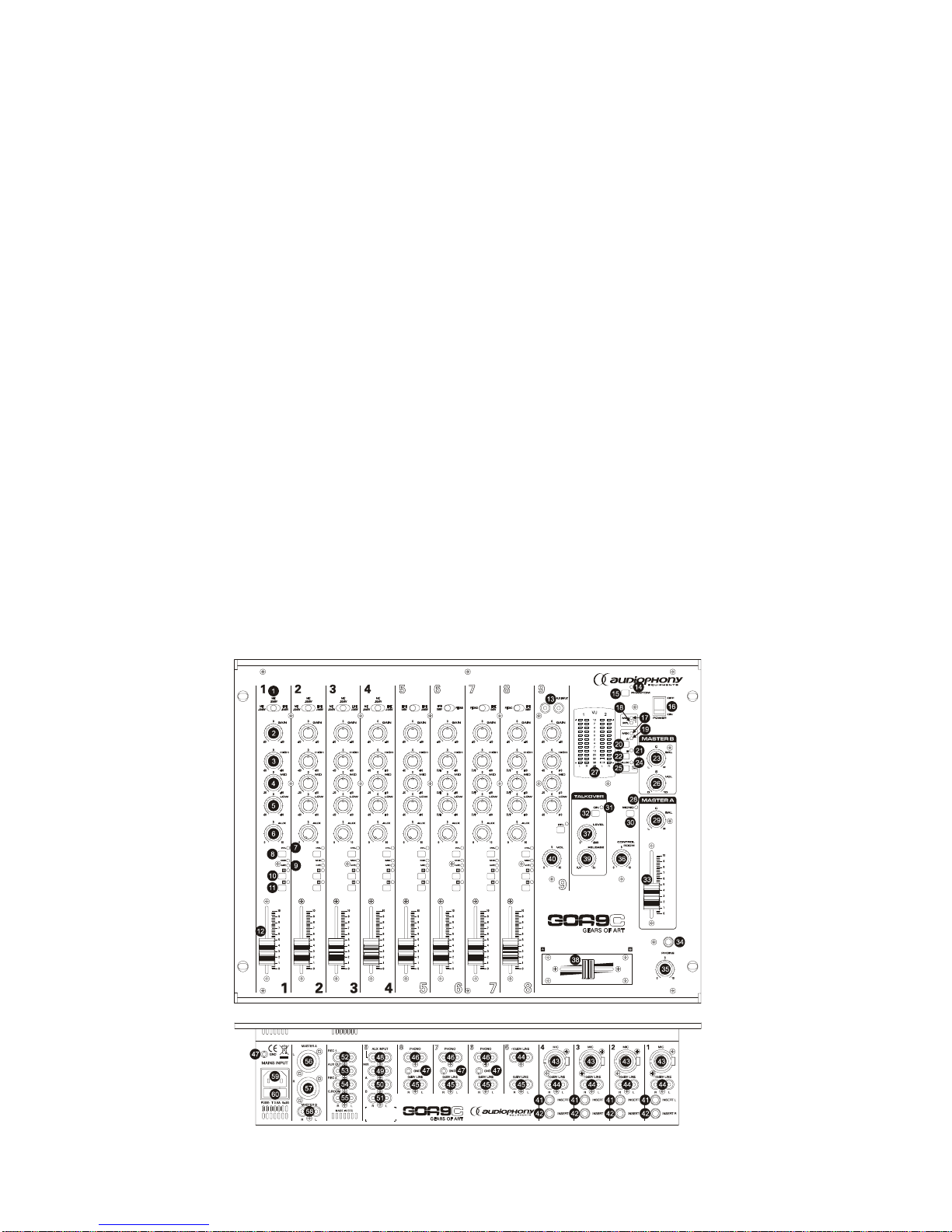
6. FUNCTION LIST
1. Input selector 31. LED indicator, TALKOVER
2. Input sensitivity adjust, GAIN 32. Talkover, ON
3. Treble control, HIGH 33. Volume control, MASTER A
4. Midrange control, MID 34. Stereo jack, headphones, PHONE
5. Bass control, LOW 35. Headphones volume control
6. Auxiliary send control, AUX 36. Room volume control, CONTROL ROOM
7. LED indicator PFL 37. Talkover effect control, LEVEL
8. Prefader listening control, PFL 38. Crossfader control
9. LED indicator 39. Talkover Recovery time control, RELEASE
10. Send to A switch, A 40. Channel gain, VOL
11. Send to B switch, B 41. Effect input/output. Left channel, INSERT L
12. Channel gain 42. Effect input/output. Right channel, INSERT R
13. Auxiliary front panel input, AUX INPUT 43. Microphone balanced input, MIC
14. LED indicator, PHANTOM 44. Line input, -10dBV LINE
15. Phantom switch, PHANTOM 45. Line input, 0dBV LINE
16. Switcher and start up pilot, POWER 46. Phono input, PHONO
17. LED indicator, MIX 47. Ground pin, GND
18. LED indicator, PFL 48. Auxiliar input, AUX INPUT
19. LED indicator, MASTER A 49. Mix input, MIX
20. Prelistening switch, MASTER A 50. A output, A
21. LED indicator, MASTER B 51. B output, B
22. Prelistening switch, MASTER B 52. Recording output, REC 1
23. Balance control MASTER B, BAL 53. Auxiliary output, AUX OUT
24. LED indicator, AUX 54. Recording output, REC 2
25. Prelistening switch, AUX 55. Room output, C.ROOM
26. Volume control MASTER B, VOL 56. Left channel balanced output, MASTER A L
27. LED VU Meter 57. Right channel balanced output, MASTER A R
28. LED indicator, MONO 58. RCA output, MASTER B
29. Balance control MASTER A, BAL 59. Mains socket
30. Mono/Stereo switch, MONO 60. Fuse holder
7. FUNCTION DIAGRAM

11
ÍNDICE
1. NOTA IMPORTANTE 12
1.1. Precauciones 12
2. INTRODUCCIÓN 12
3. INSTALACIÓN 13
3.1. Ubicación y montaje 13
3.2. Fuentes de señal conectables 13
4. OPERACIÓN Y USO 14
4.1. Puesta en funcionamiento 14
4.2. Monitoraje 14
4.3. Ganancia y ecualización de vía 14
4.4. Utilización del CROSSFADER 15
4.5. Envío auxiliar 15
4.6. Entrada AUX 15
4.7. Inserciones 15
4.8. Talkover 16
4.9. Salidas 16
5. CONSIDERACIONES 17
5.1. Bucles de masa, ruido de fondo 17
5.2. Limpieza 17
6. LISTA DE FUNCIONES 18
7. DIAGRAMA DE FUNCIONES 18
8. CARACTERÍSTICAS TÉCNICAS 35
9. DIAGRAMA DE CONFIGURACIÓN 36
10. DIAGRAMA DE BLOQUES 37
Todos los datos están sujetos a variación debida a tolerancias de producción. AUDIOPHONY® se reserva el derecho de
realizar cambios o mejoras en la fabricación o diseño que pudieran afectar las especificaciones.
12
1. NOTA IMPORTANTE
Agradecemos su confianza por haber elegido nuestro mezclador GOA9C. Para conseguir la
máxima operatividad y rendimiento de su mes a de mezclas es MUY IMPORTANT E antes de su conexión
leer detenidamente y tener muy presentes las consideraciones que en este manual se especifican.
Para garantizar el óptimo funcionamiento de este aparato recomendamos que su mantenimiento
sea llevado a cabo por nuestros Servicios Técnicos autorizados.
1.1. Precauciones
Este aparato debe ser conectado a tierra mediante su cable de alimentación.
No exponga el aparato a la caída de agua o salpicaduras, no ponga encima objetos con líquido ni
fuentes de llama desnuda, como velas. No obstruya los orificios de ventilación con ningún tip o de
material.
Cualquier cambio en la configuración debe ser realizado por personal técnico cualificado.
En caso de requerir alguna intervención y/o conexión desconexión del aparato debe
desconectarse previamente de la alimentación.
En el interior del aparato no existen elementos manipulables por el usuario.
2. INTRODUCCIÓN
El mezcl ador GOA9C está co ncebido para el uso en discotecas, salas d e fiesta, pubs, disco ba res
y aplicaciones de sonorización.
El GOA9C dispone de 8+1 vías mezclables, 8 canales con fader des lizante con vencional y una ví a
especial para retorno de efectos con fader rotativo a la que también puede conect ársele cualquier señal
que entregue nivel de línea. Dispone de 12 entradas estereofónicas: 3 de PHONO, 4 0dBV LINE (Línea
de alto nivel para compact disc, DAT, reproductores de MP3), 5 de –10dBV LINE, AUX INPUT y MIX; más
4 entradas preparadas para micrófonos balanceados (XLR 3). La entrada AUX INPUT se encuentra
además duplicada en el panel frontal AUX INPUT (13) para que pueda ser utilizada como entrada de
emergencia (CD portátiles, DATs portátiles o incluso walkmans) sin necesidad de tocar el conexionado.
Todos los canales disponen de un selector de entradas de palanca, control de ganancia
independiente para cada una de las vías así como cont roles de tono de tres bandas. El GOA9C incorp ora
un potenciómetro CROSSFADER reemplazable exteriormente y asignable a cualquiera de las entradas
mediante conmutadores con indicador luminoso para facilitar la identificación de las vías asignadas a
crossfader y su posición.
Todas las entradas disponen de la función PFL para monitorizar visualmente mediante el VU-Meter
y acústicamente mediante auriculares cualquier señal conectada a las entradas de la mesa.
En el GOA9C se ha cuidado por encima de todo la fiabilidad, dureza al paso del tiempo y la
máxima adaptabilidad a las necesidades del Disc-jockey, consiguien do de esta forma una tot al co mo didad
de operación.
 Loading...