

Page 1
Manual Version 1.3 - February 2007
Copyright © 2006 Audio Note (UK) Limited
Website
E-Mail
Telephone +44 (0) 1273 731498
www.audionote.co.uk
info@audionote.co.uk
Page 1
Page 2

Table of Contents
Section 1: Introduction ............................................................................................................................................................3
Section 2: Assembly................................................................................................................................................................4
Parts List..............................................................................................................................................................................4
Assembly Instructions..........................................................................................................................................................5
Copyright © 2006 Audio Note (UK) Limited
Website
E-Mail
Telephone +44 (0) 1273 731498
www.audionote.co.uk
info@audionote.co.uk
Page 2
Page 3

Section 1: Introduction
Thank you for purchasing this Audio Note product. Our goal is to provide you with the highest quality audio products
available anywhere in the world. If you encounter any problems with this product that interfere with its ability to help
reproduce music then please let us know by contacting the supplier.
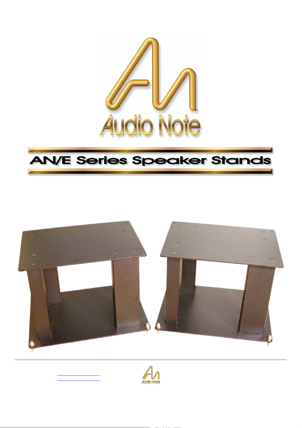
The AN/E Series Speaker Stands are a high mass design and are specially designed for the AN/E range of Audio Note
speakers. These stands can, however, be used with speakers from other manufacturers as long as such speakers are of
similar dimensions.
The stands are supplied unassembled and require assembling as per the enclosed instructions.
The stands are also designed so that they can be filled with a suitable high-density material such as a lead-shot/sand
composition or just sand on its own. Please note that if sand is used then it should be a pre-dried sand type (i.e. not
damp). You may also need to provide a seal to stop any sand from leaking from the bottoms of the columns although this
may not be necessary. A simple seal may be supplied in the form of any suitable material such as plasticine, Blu-Tack,
setting silicon rubber, etc. If you decide to fill the stands with lead-shot/sand then please bear in mind that lead is toxic
and, as such, requires that you take appropriate precautions. Some types of sand are also considered to be toxic - please
investigate this when purchasing. Children's play sand is usually non-toxic but make sure that it is pre-dried.
Spikes are supplied for both the top and bottom plates of the stands. We often recommend that the top spikes be replaced
by, or used in conjunction with, four small pea-sized pieces of Blu-Tack which are then compressed by the speaker itself;
holding it in place. This is, however, up to you and your own experimentation.
Both the upper and lower spikes are fully adjustable and lockable.
Note: Due to Audio Note’s desire to continually improve its products, specifications and materials are subject to change
without notice.
Copyright © 2006 Audio Note (UK) Limited
Website
E-Mail
Telephone +44 (0) 1273 731498
www.audionote.co.uk
info@audionote.co.uk
Page 3
Page 4

Section 2: Assembly
Parts List
2x Top plates.
The top plates have 8 countersunk holes in each of them.
16x Top plate retaining screws.
8x Columns.
16x Base plate retaining screws.
2x Base plates.
Adjustable base spike assemblies. Consisting of:
8x Brass header nuts.
8x Locking nuts.
8x Spikes.
Adjustable top plate spike assemblies. Consisting of:
8x Lock nuts.
8x Spikes.
2x Allen keys (or hex keys).
The larger one is used to tighten both the top plate and bottom plate retaining
screws.
The smaller one is used to adjust the top plate spikes.
Copyright © 2006 Audio Note (UK) Limited
Website
E-Mail
Telephone +44 (0) 1273 731498
www.audionote.co.uk
info@audionote.co.uk
Page 4
Page 5

Assembly Instructions
Assembly of the stands is quite straightforward. Please bear in mind, however, that these stands are quite heavy
(especially if you decide to fill them) so care should be taken accordingly during assembly and final positioning etc.
Construction begins with the base plate.
The base plate is the plate that does not have any
countersunk holes in it (distinguishing it from the top plate).
The picture opposite shows the base plate and highlights
the locations of the holes that will allow you to fix the four
vertical columns.
These holes will accept the button-head screws, which will
be inserted from below.
Each column should now be fixed in place onto the base
plate using the button-head screws (2 per column).
Make sure that the screws are well tightened and secure.
If you intend to fill your speaker stands then this would be a
good time to do so - although filling is optional.
For filling, we recommend either just sand or a leadshot/sand combination.
Filling is done by pouring your chosen filler through the
central hole in each of the columns.
The sand that you use should be a dry, fine one. It is also
advisable that you temporarily place some adhesive tape
over the fixing holes to stop any sand getting into the screw
threads so as not to cause problems later when you come
to screw the top plates in place. Use of a funnel is also
recommended.
Copyright © 2006 Audio Note (UK) Limited
Website
E-Mail
Telephone +44 (0) 1273 731498
www.audionote.co.uk
info@audionote.co.uk
Page 5
Page 6

The top plate can now be secured to the columns using the
countersunk-head screws.
The picture of the top plate opposite highlights the position
of these screws.
Begin by locating two screws at opposing corners. Once
done, the rest should be easier to locate.
Once again, you should make sure that these are well
tightened and secure. It is best to locate all of the screws in
their holes first before fully tightening them so that the top
plate can be moved a little while positioning them.
To fit the spikes onto the base plate, take a spike and add a
lock nut (see item 1 opposite).
Next, screw the spike into the base plate from the bottom
(see item 2).
Now the brass header nut can be attached to the top of the
spike (see item 3). Screw this all the way onto the spike.
Finally, the spike should be adjusted to the required height
before tightening all the nuts. The nut on the bottom is the
main locking nut for the spike.
It is advisable to use two spanners (wrenches) to do this.
The one holding the header nut should remain stationary
and the lock nut should be the one being tightened.
If the use of spikes is not required (perhaps because of
expensive wooden flooring etc.) then you may invert this
assembly so that the header nuts become the feet - thus
facing the spikes upward. However, if you intend to do this
then please bear in mind that the spike could pose a
danger in that configuration and should therefore be
covered in some way to prevent potential accidents from
occurring. Audio Note cannot accept responsibility for any
accidents that occur from bare spikes.
Copyright © 2006 Audio Note (UK) Limited
Website
E-Mail
Telephone +44 (0) 1273 731498
www.audionote.co.uk
info@audionote.co.uk
Page 6
Page 7

The top spikes are actually blunt so that they won't bite into
the speaker cabinets like sharp ones would.
The spike itself (item 1 opposite) should be screwed into
the top panels from the underside.
The spike can be adjusted using the provided allen key
(item 3).
Once at the required height, the lock nut (item 2) can be
tightened. It may help to hold the spike in place with the
allen key whilst doing so.
Once the above instructions have been applied to both speaker stands, the stands should be ready for use.
The stands should present a very solid foundation for your speakers. If they can be rocked from side to side, you may
need to re-adjust the bottom spikes to level them.
We wish you many years of happiness with this product.
Copyright © 2006 Audio Note (UK) Limited
Website
E-Mail
Telephone +44 (0) 1273 731498
www.audionote.co.uk
info@audionote.co.uk
Page 7
 Loading...